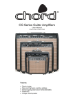
1
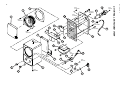
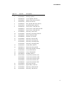
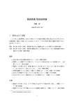
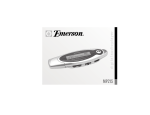
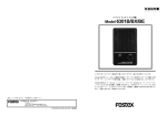
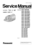
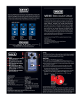
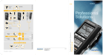
Service Manual
6301B
Personal Monitor Self-Powered
CAUTION:
CAUTION
TO PREVENT ELECTRIC SHOCK, MATCH
RISK OF ELECTRIC SHOCK
DO NOT OPEN
WIDE BLADE OF PLUG TO WIDE SLOT,
FULLY INSERT.
ATTENTION:
CAUTION: TO REDUCE THE RISK OF ELECTRIC SHOCK,
POUR ÉVITER LES CHOCS ÉLECTRIQUES,
DO NOT REMOVE COVER (OR BACK).
INTRODUIRE LA LAME LA PLUS LARGE DE
NO USER-SERVICEABLE PARTS INSIDE.
LA FICHE DANS LA BORNE CORRESPONDANTE DE LA PRISE ET POUSSER
REFER SERVICING TO QUALIFIED SERVICE PERSONNEL.
JUSQU' AU FOND.
The lightening flash with arrowhead symbol,
within an equilateral triangle, is intended to
alert the user to the presence of uninsulated
“dangerous voltage” within the product's enclosure that may be of sufficient magnitude to
constitute a risk of electric shock to persons.
The exclamation point within an equilateral
triangle is intended to alert the user to the
presence of important operating and maintenance (servicing) instructions in the literature
accompanying the appliance.
“WARNING”
“TO REDUCE THE RISK OF FIRE OR ELECTRIC SHOCK,
DO NOT EXPOSE THIS APPLIANCE TO RAIN OR MOISTURE.”
SAFETY INSTRUCTIONS
1.
2.
3.
4.
5.
6.
Read instructions - All the safety and operating instructions should be read before the appliance is operated.
Retain instructions - The safety and operating instructions
should be retained for future reference.
Heed warnings - All warnings on the appliance and in the
operating instructions should be adhered to.
Follow instructions - All operating and use instructions
should be followed.
Water and Moisture - The appliance should not be used
near water - for example, near a bathtub, washbowl,
kitchen sink, laundry tub, in a wet basement, or near a
swimming pool, and the like.
Carts and Stands - The appliance should be used only
with a cart or stand that is recommended by the manufacturer.
9.
10.
11.
12.
13.
14.
15.
7.
8.
An appliance and cart combination should be moved with
care. Quick stops, excessive force, and uneven surfaces
may cause the appliance and cart combination to overturn.
Wall or Ceiling Mounting - The appliance should be
mounted to a wall or ceiling only as recommended by the
manufacturer.
Ventilation - The appliance should be situated so that its
location or position does not interfere with its proper ventilation. For example, the appliance should not be situated on a bed, sofa, rug, or similar surface that may block
the ventilation openings; or, placed in a built-in installation, such as a bookcase or cabinet that may impede the
flow of air through the ventilation openings.
16.
17.
Heat - The appliance should be situated away from heat
sources such as radiators, heat registers, stoves, or other
appliances (including amplifiers) that produce heat.
Power Sources - The appliance should be connected to a
power supply only of the type described in the operating
instructions or as marked on the appliance.
Grounding or Polarization - The precautions that should
be taken so that the grounding or polarization means of
an appliance is not defeated.
Power Cord Protection - Power supply cords should be
routed so that they are not likely to be walked on or
pinched by items placed upon or against them, paying
particular attention to cords at plugs, convenience receptacles, and the point where they exit from the appliance.
Cleaning - The appliance should be cleaned only as recommended by the manufacturer.
Nonuse Periods - The power cord of the appliance should
be unplugged from the outlet when left unused for a long
period of time.
Object and Liquid Entry - Care should be taken so that
objects do not fall and liquids are not spilled into the enclosure through openings.
Damage requiring Service - The appliance should be serviced by qualified service personnel when:
A. The power supply cord or the plug has been damaged;
or
B. Objects have fallen, or liquid has been spilled into the
appliance; or
C. The appliance has been exposed to rain; or
D. The appliance does not appear to operate normally or
exhibits a marked changed in performance; or
E. The appliance has been dropped, or the enclosure
damaged.
Servicing - The user should not attempt to service the appliance beyond that described in the operating instructions. All other servicing should be referred to qualified
service personnel.
6301B/BX/BE
TABLE OF CONTENTS
1. SPECIFICATIONS ........................................................................................ 3
2. OVERALL EXPLODED VIEW .................................................................. 4
3. PCB ASSY AND PARTS LIST ................................................................. 6
4. PATTERN DRAWING .................................................................................. 8
5. CIRCUIT DIAGRAMS .................................................................................. 9
NOTES
• Adjustment procedures, parts list, pattern drawing and circuit diagrams are given in this manual to assist
the service technician in maintaining the 6301B.
• For your information, this service manual complies to the 6301B with the followings are the serial
number of 6301B.
USA/CND
EUR
: 0260001 and onwards
: 0660001 and onwards
UK
JPN
: 0760001 and onwards
: 1060001 and onwards
1. SPECIFICATIONS
SPEAKER ( Internal )
Type
Impedance
Efficiency
10cm Full Range Single Cone
4Ω
84 dB/W (1m)
AMPLIFIER
Normal Input Level
Output
Frequency Response
Distortion
Residual Noise
Input Sensitivity
Input Impedance
-10dBV
more than 10Wrms ( 8 Ω load )
20 ~ 50 kHz +0dB-3dB
0.05 % or less ( at 1W output )
-70dBV (0.3mV)
Unbalanced type
: -6dBV (0.5Vrms)
Balanced type
: +4dBm (1.2Vrms)
Unbalanced type
: Higher than 20kΩ
Balanced type
: Higher than 10kΩ
GENERAL
Dimensions
Weight
Power supply
JPN
USA/CND
EUR/UK
Power consumption
120 (W) × 188 (H) × 118 (D) mm
3.0 kg
100 VAC, 50/60 Hz
120 VAC, 60 Hz
230 VAC, 50/60 Hz
33 W
3
BTT
4x12 Bzn
15
3
BTT
4x12 Bzn
19
P 4x10 Bzn
13
9
BTT
4x12 Bzn
12
BTT
4x12 Bzn
7
16
14
PTT
4x8 Bzn
10
11
8
PTT
3x6 Czn
22
21
7
4
15
PTT
3x6 Czn
6
5
17
PTP WH
3x10 Bzn
PTT
4x8 Bzn
23
24
15
15
20
2. OVERALL EXPLODED VIEW
1
PTT
3x8 Ni
6301B/BX/BE
4
18
BTT
4x12 Bzn
2
6301B/BX/BE
Ref. No.
1
Part No.
8278001000
Description
Speaker, 10F05AV
2
3
8216034000
8220462100
Packing, Speaker
Cover, Speaker, B3/X/E
4
5
8226050000
8226067000
Button, Push, Power, B3/X/E
Knob, Pot, B3/X/E
6
7
8210020100
8216213002
Box, Speaker, B3/X/E (192631)
Sound Absorbent, B3/X/E
8
8242041200
8242042001
Trans, Power, 120V, B3/X/E
Trans, Power, 220V/240V, B3/X/E
9
8242040200
8274209000
Trans, Power, 100V, B3/X/E
PCB Assy, Trans, B3X
10
11
8274216000
8220464000
PCB Assy, PowerAmp, B3/X/E
Bracket, PCB, B3/X/E
12
13
8239002000
8274210000
Insulator, IC, B3/X/E
PCB Assy, JK2, B3/X/E
14
8274211000
8274212000
PCB Assy, LineAmp, B3
PCB Assy, LineAmp, B3X
8274213000
8216198100
PCB Assy, LineAmp, B3E
Gasket, Rear, B3/X/E
16
8220463201
8220463202
Panel, Rear, B3 (192630)
Panel, Rear, B3X/E (192629)
17
18
8216196000
8245392000
Cover, XLR, B3X/E
Conn, XLR, B3X/E
19
20
8207000209
8276217000
Bushing, B3/X/E
Cord, Power, B3/X/E, CSA
8276215000
8276216000
Cord, Power, B3/X/E, CND
Cord, Power, B3/X/E, EUR
8276879000
8276003000
Cord, Power, B3/X/E, UK
Cord, Power, B3/X/E, JPN
21
22
8253014008
8256075005
SW, Power, B3/X/E
Spark-Killer, 0.0047µF
23
24
8274214000
8274215000
PCB Assy, LED, B3/X/E
PCB Assy, VR, B3/X/E
15
5
6301B/BX/BE
3. PCB ASSY AND PARTS LIST
PCB Assy PowerAmp 8274216000
Ref. No.
C001
C002
C003, 004
C005
C006
C007
C008, 009
C010
C011, 012
D001
R001
R002
R004
R005
R006
R007
R008
R010
U001
Part No.
8232050471
8232098105
8232097227
8232095476
8232026123
8232026104
8232074000
8232026103
8232133478
8234001607
8230004102
8230004563
8230004122
8230004563
8230004153
8230004102
8230004100
8230004222
8234045600
PCB Assy LineAmp
Ref. No.
C021, 022
C021, 022
C023
C024, 025
R021
R022
R022
R023
R024
R024
R025
R026
R027
R028, 029
U002
DZ001, 002
CN002
JK001
JP006, 007
6
Description
CAP, CER, 50V, 470pF, 5%
CAP, ALU, 50V, 1µF, 20%
CAP, ALU, 35V, 220µF, 20%
CAP, ALU, 16V, 47µF, 20%
CAP, PES, 50V, 0.012µF, 5%
CAP, PES, 50V, 0.1µF, 5%
CAP, CER, 50V, 0.1µF, 20%
CAP, PES, 50V, 0.01µF, 5%
CAP, ALU, 35V, 4700µF, 20%
D, STACK, 2W02G
RES, CARBON, 1/4W, 1K, 5%
RES, CARBON, 1/4W, 56K, 5%
RES, CARBON, 1/4W, 1.2K, 5%
RES, CARBON, 1/4W, 56K, 5%
RES, CARBON, 1/4W, 15K, 5%
RES, CARBON, 1/4W, 1K, 5%
RES, CARBON, 1/4W, 10, 5%
RES, CARBON, 1/4W, 2.2K, 5%
IC, PowerAmp, TDA2050
B
*
*
*
*
*
*
*
*
*
*
*
*
*
*
*
*
*
*
*
BX
*
*
*
*
*
*
*
*
*
*
*
*
*
*
*
*
*
*
*
BE
*
*
*
*
*
*
*
*
*
*
*
*
*
*
*
*
*
*
*
B
BX
BE
*
8274211000
Part No.
8232095106
8232095106
8232096476
8230004103
8230004103
8230004102
8230004392
8230004103
8230004392
8230004103
8230004392
8230004102
82360212000
8234503959
8245053003
8245103000
Description
CAP, ALU, 16V, 10µF, 20%
Jumper
CAP, ALU, 16V, 10µF, 20%
CAP, ALU, 25V, 47µF, 20%
RES, CARBON, 1/4W, 10K, 5%
RES, CARBON, 1/4W, 10K, 5%
RES, CARBON, 1/4W, 1K, 5%
RES, CARBON, 1/4W, 3.9K, 5%
RES, CARBON, 1/4W, 10K, 5%
Jumper
RES, CARBON, 1/4W, 3.9K, 5%
RES, CARBON, 1/4W, 10K, 5%
RES, CARBON, 1/4W, 3.9K, 5%
RES, CARBON, 1/4W, 1K, 5%
IC, Analog, NJM4560DX
D, ZENER, MTZ J 15C
Conn, JACK, 8263, 3P, WHT
Conn, Phone, B/BX/BE
Jumper
*
*
*
*
*
*
*
*
*
*
*
*
*
*
*
*
*
*
*
*
*
*
*
*
*
*
*
6301B/BX/BE
PCB Assy JK2
Ref. No.
JK002
Part No.
8245103000
PCB Assy VR
Ref. No.
VR001
B
*
BX
*
BE
*
Description
POT, 50KA, B/BX/BE
B
*
BX
*
BE
*
B
*
BX
*
BE
*
B
BX
*
*
*
*
BE
8274214000
Part No.
8234006400
PCB Assy TRANS
Ref. No.
R031, 032
R034
T002
CN002
Description
Conn, Phone, B/BX/BE
8274215000
Part No.
8240212002
PCB Assy LED
Ref. No.
D002
8274210000
Description
OPT, LED, RED, GL-3PR8
8274209000
Part No.
8230004512
8230004102
8242099000
8245053003
Description
RES, CARBON, 1/4W, 5.1K, 5%
RES, CARBON, 1/4W, 1K, 5%
TRANS, LINE, BX
Conn, JACK, 8263, 3P, WHT
7
N
W13
W10
TO SPK G
I
O
G S V+ VR28
R29
C21
R21
JP7
JK1
ZD2
R27
U2
C23
C22
R26
R25
R22
R24
R23
JP6
R5
U1
JK2
I
G
6301-104 VR
O
VR1 W41
G I/P S G
N
6301-105 LED
C2
R2
R1
C1
6301-101
POWER AMP
BRN
T2
ORG
R31
R34
W62
D2
G
RED
CN1
BLK
R32
6301-106
TRANS
YEL
G S V+ V-
G I/P S G
6301-102 LINE AMP
ORG ORG BLK
W11
CN2/W26
C24
U3
R8
C25
W15 P
W21
R10
D1
ZD1
R7
C10
C7
C6
R6
R4
C5
C12
C4
C9
W31 6301-103
C8
C11
P
W51
C3
W12
W14
8
4. PATTERN DRAWING
6301B/BX/BE
+VCC1
C3
220/35
6301-104
3
W14
W41
VR1
50KA
2
1
4
3
2
1
C2
1/50
R1
1K
1
2
3
4
TDA2050
6301-103
C8
0.1
5
W13
3
2
1
1
4
2
U1
3
R2
56K
C1
470P
C9
0.1
C4
220/35
EXT SP
W31
2
4
1
3
2
1
R8
10
JK2
W10
2
1
C10
0.01
SP
-VCC1
SP1
PGND1
C6
0.012
R5
56K
R4
1.2K
5. CIRCUIT DIAGRAMS
6301-101
6301B
R7
1K
R6
15K
C7
0.1
6301-102
C5
47/16
W12
W21
JK1
2
4
1
1
2
3
4
1
2
3
4
SGND1
+VCC1
6301-105
R10
2.2K
W15
1
2
W51
D2
1
2
POWER LED
PGND1
S1
P1
W11
T1
ORG
2
Z1
+VCC1
D1
BLK
4
1
C11
4700/35
3
ORG
C12
4700/35
PGND1
-VCC1
SGND1
9
6301B/BX/BE
AC POWER IN
6301B/BX/BE
10
6301-106
6301BX
R31
5.1K
WIPT
2
CN1
R34
1K
3
2
1
3
2
1
RED
WHT
W62
ORG
1
RED
1
3
2
1
YEL
1
6301-104
3
R32
5.1K
1
GND
J3
T2
BRN
1
BLK
VR1
50KA
1
W41
4
3
2
1
2
3
BALANCE
INPUT
1
6301-101
+VCC1
6301-102
R23
3.9K
W14
+VCC
C21
NON
CN2/W26
3
2
1
R22
1K
JP7
SGND
R27
3.9K
8
2
3
R21
NON
1
4560
R25
3.9K
U2A
4
R24
10K
JP6
5
TDA2050
SGND
W13
3
2
1
4
R2
56K
C1
470P
7
U1
3
C9
0.1
-VCC
SGND
C4
220/35
C23
10/16
W10
2
1
C10
0.01
SP
SP1
PGND1
+VCC
R28
1K
R4
1.2K
ZD1
15B2
C6
0.012
ZD2
15B2
1
2
3
4
R29
1K
R7
1K
R6
15K
C7
0.1
C5
47/16
W12
W21
C25
47/25
JK2
-VCC1
SGND
SGND
2
4
1
3
2
1
R8
10
R5
56K
C24
47/25
EXT SP
W31
U2B
C22
NON
JK1
2
4
1
6301-103
C8
0.1
5
1
2
6
4560
C2
1/50
R1
1K
1
2
3
4
R26
NON
SGND
UNBALANCE
INPUT
C3
220/35
1
2
3
4
SGND1
+VCC1
-VCC
6301-105
R10
2.2K
W15
1
2
W51
D2
1
2
POWER LED
PGND1
S1
P1
W11
T1
ORG
2
Z1
+VCC1
D1
AC POWER IN
BLK
4
1
C11
4700/35
3
ORG
C12
4700/35
PGND1
-VCC1
SGND1
6301BE
6301-104
3
W41
4
3
2
1
2
VR1
50KA
1
6301-101
+VCC1
6301-102
BALANCE
INPUT
2
WIPT
C21
10/16
CN2/W26
3
2
1
1
GND
J3
R23
3.9K
W14
+VCC
3
2
1
RED
WHT
C3
220/35
R22
10K
8
2
3
R21
10K
JP7
SGND
SGND
1
4560
R25
3.9K
U2A
4
R24
NON
3
R27
3.9K
JP6
C22
10/16
6301-103
C8
0.1
5
W13
3
2
1
1
4
R2
56K
C1
470P
7
4560
TDA2050
2
6
5
C2
1/50
R1
1K
1
2
3
4
U1
3
C9
0.1
2
4
1
R8
10
JK2
U2B
-VCC
SGND
C4
220/35
C23
10/16
W10
2
1
C10
0.01
R26
10K
SGND
EXT SP
W31
3
2
1
SP
-VCC1
UNBALANCE
INPUT
JK1
2
4
1
SP1
PGND1
C6
0.012
R5
56K
+VCC
R28
1K
SGND
ZD1
15B2
C24
47/25
SGND
R4
1.2K
ZD2
15B2
C25
47/25
R29
1K
R6
15K
C7
0.1
C5
47/16
W12
W21
1
2
3
4
1
2
3
4
R7
1K
SGND1
+VCC1
-VCC
6301-105
R10
2.2K
W15
1
2
W51
D2
1
2
POWER LED
PGND1
S1
P1
W11
T1
ORG
2
Z1
+VCC1
D1
AC POWER IN
BLK
4
1
C11
4700/35
ORG
C12
4700/35
PGND1
-VCC1
SGND1
11
6301B/BX/BE
3
FOSTEX CORPORATION 3-2-35 Musashino, Akishima, Tokyo, Japan 196-0021
FOSTEX CORPORATION OF AMERICA 15431 Blackburn Ave., Norwalk, CA 90650, U.S.A.
© PRINTED IN JAPAN FEB 1999 8288779000