1
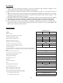
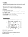
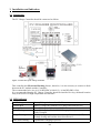
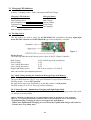
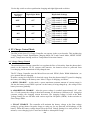
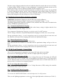
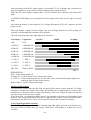
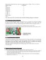
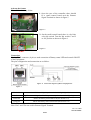
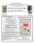
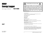
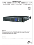
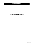
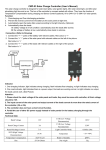
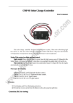
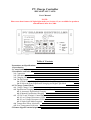
PV Charge Controller
SBC-6108 / 6112 / 6120
User's Manual
NOTE:
Please note that features 10 Night-light mode (see Section 4.3) are available for products
manufactured after Oct, 2004.
Table of Contents
Precautions and Specifications
1. Introduction
2. Control and Indicator
3. Installation and Indication
3.1 Connection
3.2 LED Indicator
3.3 Charging LED Indicator
3.4 The Dip Switch
3.4.1 Bulk Charge Voltage Setting for Sealed and Wet-type Lead Acid Battery
3.4.2 Select the Auto-Equalization charging and Night-Light Mode
4. PV Charge Control Mode
4.1 3-Stage Charge Control
4.2 Equalization Charging Mode (Automatic or Manual)
4.2.1 Automatic Equalization Charging
4.2.2 Manual Equalization Charging
4.3 12V DC Load Terminal- Control Mode
4.3.1 Low Voltage Disconnect (LVD)
4.3.2 Low Voltage Reconnect (LVR)
4.3.3 Night-Light Mode Programs
4.4 Temperature Sensor (Optional)
4.5 Over Temperature Protection
5. Remote Signal Terminal (Optional)
1
2
2
3
3
3
4
4
4
4
5
5
6
6
6
6
6
6
6
8
8
8
Precautions
1. Before using the charge/load controller, read all the instructions and cautionary markings on the
charge/load controller, the batteries and the photovoltaic panels.
2. Do not attempt to repair the controller. Incorrect re-assembly may result in a risk of electric shock or
fire.
3. To reduce risk of electric shock, disconnect all wiring before attempting any maintenance or cleaning.
Turning off controls will not reduce this risk. PV panels produce power when exposed to light – cover
them with opaque material before servicing.
4. Working in Vicinity of a Lead Acid Battery is dangerous. Batteries generate EXPLOSIVE gases during
normal operation. Provide ventilation to outdoors from the highest point of the battery compartment.
5. This charge/load controller is intended to be used with a battery supply of 12 VDC nominal voltage.
6. Be extra cautious to reduce the possibility of dropping a metal tool onto batteries. It might spark or
short-circuit batteries or other electrical parts that may cause explosion. Cover wrench handles with
plastic tape or vinyl dip coating material.
Specifications
SBC-6100 Series
Models
6108
6112
Battery voltage
12V
Maximum PV panel open circuit voltage
26V
6120
Continuous load/charge current
8A
12A
20A
Maximum charge current (5 mins)
10A
15A
25A
Maximum load current (5 mins)
10A
20A
25A
Operation current(no Load and no PV)
30mA
Voltage across terminals (PV to Battery)
0.6V
0.6V
0.8V
Voltage across terminals (Battery to Load)
0.3V
0.3V
0.4V
Electronic Blocking
(To protect against reverse polarity connection of PV panel and to block
current from battery to PV panel when voltage of battery is higher than PV
panel)
Battery reverse polarity protection
Yes
Yes
Overcharge & Over-discharge protection
Yes
Battery status LED indication
5-State LED Indications
Charging status indication
3-State LED Indications
Recommended wire size
#12AWG
Weight
0.44 kg
Dimension (WxDxH)
150 x 85 x 45 mm
Fuse
15A
Operating ambient temperature
20A
-10 to 50 °C
Over temperature protection
Yes
Battery charging float voltage setting
Factory Preset 13.5V
Battery charging bulk voltage setting
Factory Preset 14.3V
DC load control mode (For DC load terminal):
Low Voltage Disconnect(LVD)
Factory Preset 11.5V
Low Voltage Reconnect(LVR)
Factory Preset 12.5V
P.1
30A
1. Introduction
The SBC-6108/6112/6120 PV Charge Controller is designed for use with all types of 12V
photovoltaic(PV) panels/systems and different types of 12V batteries, such as wet or sealed lead
acid, lead calcium, lead antimony battery.
Numerous features are provided to maximize the performance of the system:
● Electronic Blocking (To protect against reverse polarity connection of PV panel and block
current from battery to PV Panel when voltage of Battery is higher than PV panel),
● Suitable for PV panels with Open Circuit Voltage from 17 to 23V,
● Rated charging/load current 8A (SBC-6108)/ 12A(SBC-6112) / 20A(SBC-6120),
● PWM Charging,
● Build-In Microprocessor for PV charge control to maximize the charging efficiency,
● Overcharge and Over-discharge Protection,
● 3-stage Charge Control(Bulk, Absorption & Float) to allow battery be left unattended for long
period ,
● Over Temperature Protection,
● Night Light Mode 10 selections
● Short-Circuit Protection at load terminal & Battery Reverse Polarity Protection at Battery
Connection Terminal,
● Tri-Color LED indication of system and battery conditions,
● Optional Temperature Sensor for compensated battery charging,
● Optional Remote Signal Terminal.
2. Control and Indicator
The following diagram shows the hardware interface of the PV Charge Controller.
Figure. 1 Front view of PV Charge Controller
1.
2.
3.
4.
5.
6.
7.
8.
9.
Battery LED Indicator
Lighting Programmer (Night-Light Mode Selections)
Charging LED Indicator
Reset button (see Section 3.4)
Temperature Sensor (Optional)
12V DC Load terminal with Low Voltage Disconnect/NIGHT-LIGHT mode (Section 4.3)
12V Battery connection terminal
PV Panel connection terminal
Remote Signal Terminal (Optional)
P.2
3. Installation and Indication
3.1 Connection
The PV Charge Controller should be connected as follow:
Figure. 2 Connection of PV Charge Controller
This controller has Electronic Blocking feature, therefore, it is not necessary to connect a diode
between the PV module and the Controller.
The recommended wire size is #12AWG(SBC-6108/6112) / #10AWG(SBC-6120).
It is recommended that the PV Charge Controller should be installed in a dry, sheltered location
away from sources of high temperature and moisture.
3.2 LED Indicator
Red Flashing....................
Constant Red...................
Constant Green................
Green Flashing................
Battery Voltage is lower than 12.6V
Battery Voltage has reached Low Voltage Disconnect(LVD)
Battery Voltage is higher than 12.6V
Battery Voltage has reached Bulk Charging Setting.
(Fully Charged)
Orange Flashing............... Battery Voltage is lower than Low Voltage Disconnect (LVD)
Voltage Setting and load has been disconnected.
Red-Green Flashing......... Equalization Charging in process.
Table 1 LED Indications
P.3
3.3 Charging LED Indicator
It shows 3 charging modes – Bulk, Absorption and Float Charge.
Charging LED Indicator
Charging Status
Fast Flashing Green
Slow Flashing Green
Constant Green
LED off
Bulk Charge
Absorb Charge
Float Charge
No Charging
Table 2 Charging LED Indicator
3.4 The Dip Switch
The dip switch are used to select the AUTO/MANUAL equalization charging, night-light
mode ON/OFF selection and WET/SEALED type Lead-Acid battery selection.
Figure. 3
Factory Preset
The following table shows the factory preset values of the PV Charge Controller :
Bulk Voltage
Float Voltage
Low Voltage Disconnect
Low Voltage Reconnect
Night Light Mode Option
14.3V (Sealed-type lead acid battery)
13.5V
11.5V
12.5V
Off (refer to section 4.3.3 table 5)
Table 3 Preset values of the adjustable parameters
3.4.1 Bulk Voltage Setting for Sealed and Wet-type Lead Acid Battery
The bulk voltage of sealed gel-type and wet-type lead acid battery are different.
The preset Bulk Setpoint (14.3V) is for typical Sealed Gel-type Lead Acid Battery.
The Dip switch 1 is set to OFF position .
For typical Wet-type Lead Acid Battery, set the Dip switch 1 to ON position.
The bulk voltage is 14.6V for Wet-type Lead Acid battery.
3.4.2 Select the Auto - Equalization Charging and Night-Light Mode
The dip switch 3 is for Night-Light Mode , switch 2 for Equalization Charging mode and switch
1 is always set at off position
THE PV CHARGE CONTROLLER IS FACTORY PRESET FOR USE WITH SEAL TYPE BATTERY
THAT IS : NO AUTO EQUILIZATION CHARGING BECAUSE DIP SWITCH 2 IS AT ON POSITION.
* Equalization(Eq.) charging is only for wet-type Lead Acid Battery
When Auto-Equalization Charging is set at ON mode, Equalization charge will occur for
2 hours once every thirty days.
P.4
Use the dip switch to select equalization charging and night-light mode as below:
AUTO
Night-Light Mode
Dip Switch Settings
OFF
OFF
Dip switch 3 – OFF
Dip switch 2 – ON
Dip switch 1 - OFF
OFF
ON
ON
OFF
Equalization
Charging*
ON
Factory
Preset
Dip switch 3 – ON
Dip switch 2 – ON
Dip switch 1 - OFF
Dip switch 3 – OFF
Dip switch 2 – OFF
Dip switch 1 - OFF
Dip switch 3 – ON
Dip switch 2 – OFF
Dip switch 1 - OFF
ON
Table 4 Dip Switch Functions
4. PV Charge Control Mode
The SBC-6100 Series PV Charge Controller can operate in the several modes. This includes the
3-stage Charge Control, Equalization Charging Mode, DC Load Control Mode, NIGHT-LIGHT
mode, Temperature Sensing and Over Temperature Protection features.
4.1 3-Stage Charge Control
The main function of charge controller is to regulate the flow of electricity from the photovoltaic
panels to the batteries. In PV systems with batteries, the batteries must be protected from
overcharging and be maintained at fully charged state.
The PV Charge Controller uses the Micro-Processor and PWM ( Pulse Width Modulation ) to
give optimal and safe charging .
It makes varying On-Off pulses of electrical energy from the photovoltaic(PV) panel in charging
the battery according to the battery state. It has 3 stages of charging, as follows:
a. BULK CHARGE – At this mode, a preset maximum constant amount of current (amps) is
fed into the battery as no PWM is present. As the battery is being charged up , the voltage of the
battery increases gradually.
b. ABSORPTION CHARGE – After the preset voltage is reached (approximately 14.3 volts
for a 12 volt system) the voltage is then held constant. As the battery continues to be charged at
constant voltage, the charging current decreases. The charging voltage is held at the Bulk
Voltage Setting for one full hour with various rapid On-Off pulses (PWM). It then switches to
Float Charge Mode.
c. FLOAT CHARGE –The controller will maintain the battery voltage at the float voltage
setting by giving shorter On-pulse charge to make up for any detected self discharge of the
battery. When the battery voltage drops below the Float Voltage Setting for a total period of 10
minutes, a new charging cycle is activated in Bulk or Absorption Charge.
P.5
The three stages charging method works well with the chemical reaction that occurs as a battery
is being charged. When a battery is more discharged, a regulated maximum current can be
applied, since there is a lot of material available for the reactions to occur.
As the battery refills, less and less chemical material is available for the reaction. By using PWM
to slowly reducing the charge current, while maintaining a preset high voltage, the battery is
more closely refilled at the reaction rate of the chemicals. Finally, the Float voltage keeps the
battery fully charged at all times taking care of the self discharge .
4.2 Equalization Charging Mode (Automatic or Manual)
WARNING: Equalization Charging is only for Wet-type Lead Acid Battery.
The Equalization Charging Voltage is factory pre-set to the Bulk Voltage + 1 Volt.
The battery manufacturer should be consulted. Clean, distilled water will need to be added to the
battery AFTER the equalization process.
4.2.1 Automatic Equalization Charging
Automatic Equalization charge is only available when battery voltage is higher than the Low
Voltage Disconnect (LVD) voltage , see 4.3.1.
To set Automatic Equalization Charging, set the dip switch 2 to OFF position.
The PV Charge Controller will perform Equalization charging for 2 hours once every 30 days
During equalization charge , it can be stopped any time by pressing the Reset button once and
the controller will return to the charging mode before the Equalization charge.
4.2.2 Manual Equalization Charging
Set the Night-Light Mode , dip switch 3 to off position.
Press and hold the Reset button for 10seconds and the equalization charge will go on for two
hour.
During equalization charge , it can be stopped any time by pressing the Reset button once and
the controller will return to the charging mode before the Equalization charge.
4.3 12V DC Load Terminal – Control Mode
The 12V DC load terminal is designed for low power DC load such as street light.
It prevents over-discharging the battery and has 10 Night-Light timer programs.
4.3.1 Low Voltage Disconnect (LVD)
When the battery voltage is lower than the Low Voltage Disconnect (LVD) setting, the LED will
blink orange once every 2 seconds. After it has flashed several times (up to 5), the load will be
cut off. After the load is cut off, user can press the Reset button once to switch on the load for a
grace period of 10 minutes for emergency purpose.
4.3.2 Low Voltage Reconnect (LVR)
When the battery voltage is higher than Low Voltage Reconnect (LVR) setting, the controller
will automatically reconnect the load.
4.3.3 NIGHT-LIGHT Mode Programs
In the night-light mode, we have 10 selections.
To Activate the NIGHT-LIGHT Mode, switch the dipswitch 3 to ON position.
Then, use the lighting programmer to select one of the night-light mode selections.(see Table 5)
P.6
After activating, when the PV panel voltage is lower than 3.5V for 10 minute, the Controller will
turn on the light for a preset period of time according to the option selected.
When the PV panel voltage is higher than 3.5V for 10minute, the Controller will turn off the
light.
In NIGHT-LIGHT Mode, press and hold the Reset button can switch on the Light to test the
light.
Also, when the battery is lower than the Low Voltage Disconnect (LVD) for 2 minutes, the load
will be cut off.
When the battery voltage becomes higher than Low Voltage Reconnect (LVR) setting, the
controller will automatically reconnect the load again.
The following chart shows the night light mode selections.
LCD Display
Explanation
OFF
OFF
2 HR ON
2 HOURS ON
4 HR ON
4 HOURS ON
6 HR ON
6 HOURS ON
8 HR ON
8 HOURS ON
10 HR ON
10 HOURS ON
3 / OFF / 1
3 / OFF / 1
4 / OFF /2
4 / OFF /2
6 / OFF /2
6 / OFF /2
DK--DN
Dusk to Dawn
SUNSET
NIGHT
SUNRISE
Table 5
DESCRIPTION:
OFF – Load remain turned off.
X Hours On – Load is turned on for X hours after sunset.
Y / OFF / Z – Load is turned on after for Y hours after sunset, turned off during the night, then
turned on again Z hours before sunrise.
Dusk to Dawn – Load is turned on all night.
Measure Night Length
The load timer options that turn the load on again before sunrise require that the PV charge
controller to measure the length of the night. The default value of night length is 12 hours after
installation (or disconnect then reconnect the battery). The local length of night will take the
moving average of 4 consecutive nights.
If the solar array is disconnected during service, the controller will then record premature night
duration. This wrong night length data will be outdated after another 4 days of normal service.
Alternatively, the above error can be corrected by disconnect then reconnect the battery.
Verify Night-Light Mode selection
To verify the night-light mode selection. During night-light mode, press the reset button once.
The green LED will flash once per second. Count these LED flashes to confirm the correct
selection.
P.7
Each of the 10 night-light mode options has a unique number of flashes. These are as follows:
Switch Setting
# of Flashes
OFF
0
2 Hours On
1
4 Hours On
2
6 Hours On
3
8 Hours On
4
10 Hours On
5
3 / OFF / 1
6
4 / OFF / 2
7
6 / OFF / 2
8
Dusk to Dawn
9
Table 6
Note: Do not press the reset button when the LED is flashing during the verification.
4.4 Temperature Sensor (Optional)
When an external temperature sensor (optional accessory) is installed, the controller will adjust
the Bulk and Float Charge Voltage according to the temperature of the battery type. The
regulation setpoint is 25ºC. The Controller adjusts the BULK and FLOAT setpoints -0.03V/ ºC.
Only the factory provided temperature sensor (optional accessory) can be used.
If no temperature sensor is installed, the controller will set the temperature of the battery at 25ºC.
Figure. 4
4.5 Over Temperature Protection
The operation temperature of the transistors of the PV Charge Controller is also continuously
monitored. If excessive temperature is detected, the charge controller transistors will repeatedly
and rapidly turn On and Off to reduce the charging rate so as to reduce the transistors'
temperature. In case the charging current (from the solar panel) is reduced to zero and over
temperature condition still persists, the load will also be disconnected.
When the temperature has dropped to the working range, the PV panel and the load will be
connected again.
5. Remote Signal Terminal (Optional)
The PV controller has a remote signal output terminal (Optional) which can:
1. control the ON/OFF operation of equipment such as inverter hooked up to the battery bank to
operate along with the night-light mode program and share the safeguard function such as
low battery disconnect and reconnect.
2. make extension connection of the battery status LED to allow remote monitoring Battery
bank status (see Section 3.2)
P.8
Activate the feature
Please follow the steps below:
1. Open the case of the controller, there should
be a small control board near the Remote
Signal Terminal as shown in figure 5.
Figure. 5
2. On the small control board, there is a sky blue
color dip switch. Turn the dip switch 1 and 2
to ON position as shown in figure 6.
Figure. 6
Connection
Use the RJ-45 connector (8-pin) to make extension of Battery status LED and control ON/OFF
of the Equipments.
The pins configuration and connection are as follow:
Figure. 8 Connection diagram of RJ-45 to Equipments.
Figure. 7
Pin 1 & 2
On/Off Control Signal synchronized with Night-light Mode
Pin 7 & 4
High/Low control signal (12V, 0V) up to 1A, synchronized with Night Light mode
Pin 6 & 4
Shows the battery status Red LED (See Section 3.2)
Pin 8 & 4
Shows the battery status Green LED (See Section 3.2)
Table 7 Pins configuration
Note: Pin 3 and 5 are not used in Remote Signal Terminal.
Rev. 1.0 11/2004
7673-6112-0562
END