1
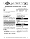
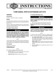
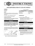
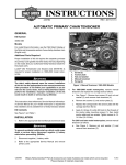
-J05236
REV. 2013-06-13
LED AUXILIARY LAMPS
GENERAL
Kit Number
73396-10A, 68000008A, 68000075
Models
These fog lamps fit all Harley-Davidson original equipment and
Genuine Motor Accessory auxiliary lamps. They are direct
replacements for the original bulbs found in the lamps.
Additional Parts Required
To prevent accidental vehicle start-up, which could cause
death or serious injury, disconnect negative (-) battery
cable before proceeding. (00048a)
1.
Refer to the service manual and follow the instructions to
remove the seat and disconnect the negative (black) battery cable from the negative (-) battery terminal. Retain all
seat mounting hardware.
2.
See Figure 4. Remove auxiliary lamp retaining screw (A)
and nut (B) from auxiliary lamp retaining ring (C). Remove
and retain retaining ring and hardware.
3.
Disconnect the wire harness plug from back of auxiliary
lamp (1).
4.
Remove lamp (1) and nesting ring (D). Discard lamp but
retain nesting ring.
5.
See Figure 1. Place the nesting ring at back of new lamp
with concave side facing away from lamp.
6.
For 2004 and earlier Touring models: Connect a Yharness (68355-05) to the auxiliary lamp connectors.
2004 and earlier Touring models: require the separate purchase of two Y-harnesses (68355-05).
The rider's safety depends upon the correct installation
of this kit. Use the appropriate service manual procedures.
If the procedure is not within your capabilities or you do
not have the correct tools, have a Harley-Davidson dealer
perform the installation. Improper installation of this kit
could result in death or serious injury. (00333a)
NOTE
This instruction sheet references service manual information.
A service manual for your model motorcycle is required for this
installation and is available from a Harley-Davidson dealer.
NOTE
If the ground wires will not mate when the connectors are
connected, see the service manual and switch the wire terminal
positions in the fog lamp connector.
This fog lamp kit requires up to 4.6 A current from the electrical
system. This may be less than the OE (original equipment)
electrical draw.
7.
Verify that when connected, the fog lamp ground wire
(black) will mate to the auxiliary light connector ground
wire (black).
8.
Connect fog lamp connector to the motorcycle auxiliary
light connector (E). Install lamp and nesting ring in housing
and be sure to align index tab (1) on lamp with pockets in
the nesting ring. Make sure that the nesting ring index tab
(2) locates in the the slot of at the bottom of the housing.
9.
Install retaining ring over lamp. Rotate retaining ring so
the screw is centered at bottom. Install nut and screw and
tighten until snug.
Kit Contents
See Figure 4 and Table 1.
INSTALLATION
For ALL vehicles with main fuse:
To prevent accidental vehicle start-up, which could cause
death or serious injury, remove main fuse before proceeding. (00251b)
NOTE
10. Repeat for the lamp on the opposite side.
11. See the service manual and connect the battery negative
cable (-) or install main fuse.
For vehicles equipped with security siren:
•
Verify that the Hands-Free Fob is present.
•
Turn the ignition key switch to IGNITION.
1.
Refer to the service manual and follow the instructions to
remove the main fuse.
For ALL vehicles with main circuit breaker:
-J05236
After installing seat, pull upward on seat to be sure it is
locked in position. While riding, a loose seat can shift
causing loss of control, which could result in death or
serious injury. (00070b)
12. If necessary, install the seat.
Many Harley-Davidson® Parts & Accessories are made of plastics and metals which can be recycled.
Please dispose of materials responsibly.
1 of 3
13. Test the LED fog lamps for proper operation.
6.
Measure the distance from the headlamp vertical centerline
to the vertical centerline of each LED fog lamp. Record
this measurement.
7.
See Figure 3. Mark the LED fog lamp horizontal and vertical centerlines (2 and 3) on the wall according to the
measurements taken in the previous steps.
14. Align the LED fog lamps.
is06633
NOTE
Follow the adjustment procedure in the service manual procedure for loosening and tightening the auxiliary lamp flare nut.
Follow this procedure for positioning the beam area of the LED
fog lights.
8.
See the service manual and loosen the auxiliary lamp
housing adjusting hardware.
9.
Cover the headlamp and right side fog lamp. Adjust the
left side fog lamp position so that:
•
The beam area (4) is horizontally centered on the left side
fog lamp center lines (2).
•
The top of the beam area is 4 in (10 cm) below the left
side fog lamp center point.
1
2
1. Lamp index tab
2. Nesting ring index tab
Figure 1. Lamp and Nesting Ring
ALIGNMENT PROCEDURE
1.
Verify that front and rear tire inflation pressures are correct
and that the suspension is adjusted to the weight of the
principal rider. Refer to the owner's manual.
10. Cover the headlamp and left side fog lamp. Adjust the
right side fog lamp position so that:
•
The beam area (5) is horizontally centered on the right
side fog lamp center lines (3).
The top of the beam area is 4 in (10 cm) below the right
side fog lamp center point.
2.
Fill the fuel tank or add ballast to equal the weight of the
fuel needed.
•
3.
See Figure 2. Position motorcycle so that front axle is 25
feet (7.6 meters) (3) from wall.
4.
Draw a vertical line (2) off of the perpendicular line (1) on
the wall, directly opposite of the motorcycle.
11. See the service manual and tighten the auxiliary lamp
housing adjusting hardware and, if necessary, front turn
signal hardware to torque specified.
is06638
is06580a
6
1
2
3
4
5
2
1
3
1. Perpendicular line
2. Headlamp vertical centerline
3. 25 feet (7.6 meters)
1.
2.
3.
4.
5.
6.
Headlamp vertical centerline
Left side LED fog lamp centerlines
Right side LED fog lamp centerlines
Left side LED fog lamp beam area
Right side LED fog lamp beam area
Distance - 4 in (10 cm)
Figure 3. Properly Aim LED Fog Lamps
Figure 2. Checking Headlamp Alignment
NOTE
As the weight of the rider will compress the suspension slightly,
have a person whose weight is roughly the same as that of the
principal rider sit on the motorcycle.
5.
With the vehicle upright and a rider seated on the motorcycle, measure the distance from the floor to the horizontal
centerline of each LED fog lamp. Record this measurement.
-J05236
2 of 3
SERVICE PARTS
Table 1. Service Parts
Item
is06630a
E
Description (Quantity)
Part Number
1
LED lamp bulb(chrome) (2)
73397-10B
1
LED lamp bulb (black)(2)
68000007A
1
LED lamp bulb (chrome)(2)
68000075
Items mentioned in text, but not included in kit.
C
D
A
1
A
Screw, retaining ring
B
Nut, retaining ring
C
Retaining ring
D
Nesting ring
E
Connector
B
Figure 4. Service Parts: LED Auxiliary Lamps
-J05236
3 of 3