1
GENUINE PARTS
INSTALLATION INSTRUCTIONS
DESCRIPTION:
APPLICATION:
PART NUMBER:
Vehicle Tracking and Recovery System
Altima Sedan and Coupe (2007-2010)
999Q8 VW000
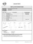
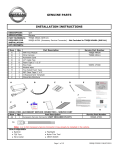
KIT CONTENTS:
Item
A
B
C
D
E
F
G
H
I
J
K
L
Qty.
1
1
1
1
1
8
2
1
10
2
1
1
Part Description
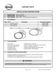
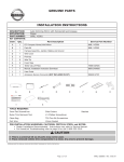
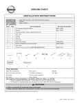
GPS Control Module
Wire Harness
I/I Download Instructions
Owners Manual
Activation Card (included in owners manual)
6" Cable Ties
12" Cable Ties
Foam Pad (on module)
Foam Tape
Posi-Taps
Mirror Hanger (Nissan VTRS information)
Alcohol wipe
Service Part Number
99Q8 VW000S1
99Q8 VW000S2
999V2 AW000
999M1 VT000
I/I
Download
Instructions
A
B
G
TOOLS REQUIRED:
● Ratchet
● 10mm socket
● #2 Phillips screwdriver
C
H
D
I
E
J
F
K
L
● Plastic pry bar
● 8mm socket
● Wire cutter
PRE-INSTALLATION WARNINGS, CAUTIONS, CRITICAL STEPS, and NOTES:
● Dealer Installation Recommended. Instructions may refer to service manual.
● This part is to be installed at a surface temperature of 65-100°F.
● Posi-Tap instructions must be followed exactly as described in this instruction
Page 1 of 9
999Q8 UW000II Rev. 09/21/2010
INSTALLATION OVERVIEW:
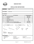
System Block Diagram
Fig.1
Control
Module
Meter connector
Ground connection
at lower driver dash
Vehicle outline with installation overview
Fig.2
Control
Module
Page 2 of 9
999Q8 UW000II Rev. 09/21/2010
INSTALLATION PROCEDURE:
1)
2)
3)
4)
5)
Apply parking brake
Turn ignition switch to "ON" position
Record the customer radio presets and other presets as required
Preset
1
2
3
4
5
6
7
Put the shift lever in"P" position for A/T or "1st" for M/T
Turn the ignition switch to "OFF" position
Fig. 3
6)
Disconnect the negative battery terminal
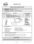
CAUTION
● Take care not to scratch or damage any component during the removal or re-installation process.
● Trim pieces found to have witness marks or broken clips are not to be reinstalled.
7) Remove the following vehicle parts in the sequence shown below. Store these re-usable parts in a safe and protected
manner.
Fig.4
3
4
1
1.
2.
3.
4.
Instrument
Instrument
Instrument
Instrument
side mask LH
lower cover LH
panel trim
panel
2
Page 3 of 9
999Q8 UW000II Rev. 09/21/2010
INSTALLATION PROCEDURE:
Fig.5
8)
Remove the instrument side mask (1)
Fig.6
9)
Remove the instrument lower cover
a) Open fuse block cover, remove serew
b) Remove instument lower cover, remove harness
connectors and aspirator tube
Fig.7
10)
1
b)
a)
1
NOTE:
It is not required to remove the steering wheel
Fig.8
a)
Remove the cluster lid (1)
11)
a)
b)
Remove the combination meter
a) Remove (2) #2 phillips screws
b) Remove combination meter and disconnect
harness
NOTE:
It is not required to remove the steering wheel
Page 4 of 9
999Q8 UW000II Rev. 09/21/2010
INSTALLATION PROCEDURE:
CAUTION
● Color(s) given in illustration(s) are for reference only. Use location(s) where color deviates.
● If a vehicle wire is being used by another accessory and a posi-Tap is present, tap the accessory wire
not the vehicle wire
● Do not pinch the harness between trim when re-installing the Instument Panel
8)
Tap the Vehicle Tracking and Recovery System Red wire to the vehicle White/blue B+ wire.
Fig.9
Meter
connector
B+
White/Blue
ACC
Purple/Yellow
Orange
1
2
3
4
5
6
7
21
22
23
24
25
26
27
28
9
10
11
29
30
31
Blue
13
Green/Black
Purple
Fig.10
9)
b)
a)
12
c)
Brown/White
14
15
16
17
18
19
20
34
35
36
37
38
39
40
White/Black
Tap vehicle wire.
a) Remove cap (slot side) from the tap body
b) Slide cap around vehicle wire.
c) Tighten the tap TIGHT with finger pressure.
NOTE:
Do not re-use the tap for subsequent reinstallation. Figures are not to scale.
Fig.11
10)
Inspect the tap to ensure correct installation.
NOTE:
Avoid putting pressure on the vehicle wire and tap
for the remainder of the installation.
i. Straight and evenly spaced all the way around
ii. Tight and minimize gap (wire jacket should
be crushed)
Page 5 of 9
999Q8 UW000II Rev. 09/21/2010
INSTALLATION PROCEDURE:
Fig.12
11)
e) Insert wire to here
c)
a)
d)
f) Tighten
Tap
a)
b)
c)
accessory wire.
Remove tap (non-pierce) side from tap.
Remove the protective stub from the wire.
Insert wire through the non-pierce side opening.
d)
e)
Spread the individual strands into fan shape.
Insert wire into the tap body and ensure that it is all
the way in.
f)
Tighten the tap TIGHT with finger pressure.
Fig.13
12)
Confirm the tapped accessory wire.
a) Inspect the tap to ensure correct installation.
b) Test the signal to ensure that it is working properly.
Fig.14
13)
Secure the tap.
a) Secure the tapped wire on the non-pierce side to the
body of the tap with electrical tape (≥ 2
revolutions).
i. Straight and evenly spaced all around
ii. Tight and no gap and test the signal
Vehicle Harness
b)
a)
b)
Secure the body to harness where vehicle wire is
being tapped with electrical tape (≥ 2 revolutions).
...
Accessory
14) Tap the Vehicle Tracking and Recovery System Brown wire to the vehicle Purple/Yellow ACC wire.
See steps 9-13 for wire tap installation instructions.
Fig.15
Meter
connector
B+
White/Blue
Blue
ACC
Purple/Yellow
Orange
1
2
3
4
5
6
7
21
22
23
24
25
26
27
Purple
28
9
10
11
29
30
31
12
13
Green/Black
Page 6 of 9
Brown/White
14
15
16
17
18
19
20
34
35
36
37
38
39
40
White/Black
999Q8 UW000II Rev. 09/21/2010
INSTALLATION PROCEDURE:
Fig.16
ground wire
14) Route the wire harness
a) Route ground wire to fuse box
b) Pull excess harness to meter cavity (below
BCM) and attach cable ties as indicated
c)
c)
c)
b)
b)
b)
Secure harness with foam tape
b)
c)
cable ties
b)
CAUTION
● When stacking multiple ground eyelets, DO NOT stack the stems of the eyelet
● When stacking multiple ground eyelets, leave a 30 spacing between the stems of the eyelet
15) Connect the ground
a) Remove the 8mm bolt in figure
b) Attach the ground eyelet to screw and re-install
Fig.17
incorrect
b)
correct
Fig.18
16) Connect the harness to the control module
Page 7 of 9
999Q8 UW000II Rev. 09/21/2010
ACCESSORY CHECK:
Connect all vehicle harness connections (without re-assemble)
Connect the battery negative terminal.
Check all Critical Installation Steps.
Verify all wiring is secure and not exposed.
Trim all excess cable ties flush.
Verify the Control Module Diagnostic L.E.D.'s are blinking Green
Verify proper Diagnostic L.E.D. blinking pattern (without engine start)
Turn ignitiom switch to "OFF: position, the Green L.E.D. will blink brightly once every three seconds
Turn ignition switch to"ON" position for ten seconds, the Green L.E.D. will continue to blink
brightly once every three seconds
Turn ignition switch to "OFF"position, the Green L.E.D. will be dim and blink once
every three seconds
Secure mirror hanger to rear view mirror
Disconnect the negative battery terminal
INSTALLATION PROCEDURE:
Fig.19
17) Prepare the module
a) Clean installation surface with ≥90%
alcohol/water solution
b)
Peel tape liner from foam pad on Module
a)
Page 8 of 9
999Q8 UW000II Rev. 09/21/2010
RE-INSTALLATION OF REMOVED PARTS:
c)
Adhere module to the air duct
Fig.20
front
AC duct
c)
18)
Re-install all removed vehicle parts. Refer to the vehicle service manual for more details.
CAUTION
Use caution when re-installing interior components to avoid damage, scratches, or breaking of
mounting clips. Refer to the vehicle service manual for more information.
FINAL INSPECTION:
Verify re-installed trim parts for proper flush fit (no gap, no waviness, etc.).
Verify all clips are fully engaged and locked.
Verify re-installed trim parts are free from cracks, scratches or stress marks.
Verify vehicle headliner, seat, steering wheel, center console, floor carpets, etc. are not soiled.
Verify interior and exterior is not damaged.
Connect the battery negative terminal and tighten the nut to appropriate torque.
Turn ignition switch to "ON" and confirm proper operation of Vehicle Systems
If equipped, verify all window and sunroof one touch operation and perform the reset procedure if
necessary. Refer to the vehicle service manual for more details.
Confirm proper audio function (AM, FM, SAT, CD and AUX).
Re-program radio presets and other vehicle settings to the recorded settings.
Start engine and verify that there are no new Diagnostic Trouble Codes and the Meter is functional. Turn ignition
switch to "OFF".
Place the Owner Manual, Quick Reference Guide, and/or other Manual in the glove box.
Posi-TapTM is protected by patent # 5,228,875 5,695,369 5,868,589 6,692,313 Jap 2881414 Aus 708700 Tia 103534
Can 2204826 Mex 200626 Korea 477279 China Z197105562.9 & others pending.
Page 9 of 9
999Q8 UW000II Rev. 09/21/2010