1
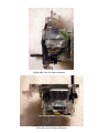
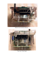
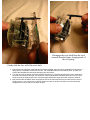
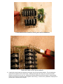
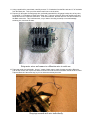
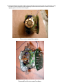
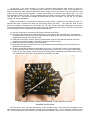
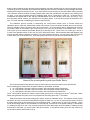
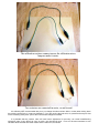
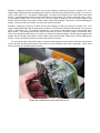
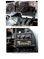
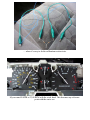
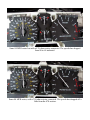
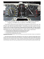
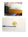
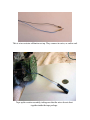
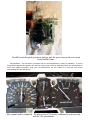
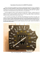
Speedometer Conversions for the MN12 Thunderbirds
There is a lot of interest in the MN12 user community in enhancing the performance of our cars. Improving the
MN12’s stock 120-mph speedometer to better read the resulting higher speeds is of continuing interest, as
evidenced by the numerous past threads dealing with finding, swapping and using the relatively rare 145-mph
speedometers used exclusively in the 94 & 95 SuperCoupes. There was also a thread awhile back regarding a
mod to produce a 165-mph speedometer; that did not work out on a long-term basis.
This writer happened to acquire a 145 SC speedo with a broken meter movement. I wanted to do the 145
swap into my 96 Bird, but this 145 speedo would have to be repaired first. I began looking into the differences
between the stock 120-mph speedometer and the 145-mph SC unit in great detail to figure out first, how they
worked, and second, how to fix my 145 unit to be able to use it.
This is a write-up of my findings, with considerable electrical detail that you can skip over if you want. The
bottom line is that I found that it is relatively easy to convert a stock 120 speedo to read out any max speed that you
would like. Although it is rather detailed and painstaking work, it can be accomplished with simple hand tools. I’ll
also describe how to calibrate the resulting 160, 180 or 200 mph speedometer without any special test gear,
although a portable GPS comes in handy for increased accuracy. While we’re in there, the odometer reading can
be reset also, if a different speedometer than original is being used for the conversion. Read on for the details, as
they say, starting with the basics.
Here’s our starting point – a clean 120 speedometer.
Right-side view for later reference.
Left-side view for later reference.
Bottom view for later reference.
Top view of stock unit.
The MN12 speedometer head unit has 3 connection pins that plug into the cluster housing. 2 pins are used for
rd
+12 volt and ground to feed power into the unit. The 3 pin connects to the vehicle speed sensor VSS system.
The electronics on the circuit boards inside the head convert the alternating current AC pulses from the VSS to 2
separate outputs. One output is a pulsed signal that feeds to a small electric motor to drive the trip odometer and
the total mileage odometer number readouts. The other output from the circuit boards is a variable DC current
source that operates an electric meter movement. The meter movement has the speedometer needle mounted to
it, and can turn through a 270° arc or partial circ le from zero to full-scale. This means that the MN12 speedometer
is basically a small DC voltmeter, a fact that will come in handy later on down the page.
The speedometer head is considered a field replacement unit or FRU. When the factory service manual
trouble-shooting procedure narrows a reported speedometer or odometer problem down to the speedometer head
itself, the manual directs the service technician that the entire head is to be replaced. There is no repair information
for the internals of the speedometer head in the factory service manual.
That doesn’t stop us, however. Operating under the theory that “If it’s already broken, we can’t hurt it much”, I
proceed to carefully disassemble a 120 unit from a wrecking-yard 93 LX and the broken 145 unit from the 95 SC at
the same time in order to compare all of the internal bits & pieces from each unit.
Side-by-side comparison of the 120 and 145 components revealed that all of the parts are the same except the
meter movement and the faceplate. This makes sense from a factory production standpoint: very few unique parts
are required to produce the different units, and maximizing parts commonality leads to lower production costs.
The different faceplate is obvious, so the remaining difference between the 120 and 145 units comes down to
the meter movement. So, what is unique and distinguishing between the two meter movements? At first it was
believed that the magnetic wire coils must be wound differently, but an ohmmeter check reveals that both meters
have the same coil resistance of 90 ohms. The 2 meter movements and a milliammeter were then connected in
series, so that the same current would flow through both of the coils and the milliammeter at the same time, and a
carefully controlled variable DC voltage was applied to the series circuit. This test revealed the difference: the 120
meter indicated full-scale at 40 milliamperes or mA of current flow while the 145 meter took 48 mA to read fullscale. Since the magnetic coils are the same, the only remaining part that could have this effect is the little coil
spring that pulls the needle back to zero when the car stops. Sure enough, a detailed visual inspection shows that
the coil return springs are different. The 145 spring is stronger, so the magnetic coil needs more current to develop
more force to reach full-scale in the 145 unit than in the 120 unit. Expressed another way, this means that the 120
unit is more sensitive to the DC current (that is, it takes less current) for a full-scale reading than is the 145 unit.
This finding is highly significant.
Changing out the coil springs in the meters looks to be just about impossible. The plastic case of the meter
movement appears to have been ultrasonically welded at the factory, so any attempt to dismantle it will result in
broken parts one way or another. Let’s look for another way to do the fix.
If we could find a way to make the 120 meter movement less sensitive, we can convert it to a 145 (or 150 or
160 or 180 or 200) speedometer. So, how do we go about making the meter less sensitive? The series test
showed that the 120 unit reads full-scale at 40 mA of current. The series test was rerun and showed that the halfscale reading took 20 mA. This means that the 120 meter response is linear to current: 10 mA is quarter-scale, 20
mA is half-scale, 30 mA is three-quarter-scale and 40 mA is full-scale. The 145 meter takes 12, 24, 36 and 48 mA,
respectively, for the same deflection amounts, showing that it too is linear.
The series current tests show that a standard 120 speedometer is set up to read 120 with 40 mA of current
through the meter movement. This means that each mA of meter current is giving us a 3-mph speed indication.
This is confirmed by the 48 mA used to get full-scale on the 145 unit: 3 x 48 mA = 144 mph, which is within meter
reading error.
So, the need is to make the standard 120 meter movement less sensitive. This is accomplished by connecting
a parallel or shunt resistor across the meter movement. This is not new idea: high-power ammeters on large
equipment use shunts in heavy current cables so that a small portion of the current can be read by the ammeter in
the cab. Same principle is used here: send part of the current through the meter and the rest of the current around
the meter through the shunt. A couple of examples will show how this works.
Example 1: I needed to convert a standard 120-mph speedometer to read from 0 to 145 mph, to repair the
defective 145 SC speedometer head. At 145 mph the meter will be getting 48 mA of current from the circuit
boards. To use a standard 120 meter at 145 mph, what I need to do is to have 40 mA flow through the meter for
full-scale and have 8 mA bypass, or go around, the meter movement. After some experimentation and drive tests
with a GPS, it was determined that the required shunt/bypass resistor value was 460 ohms. The result was a fully
functional 145-mph speedometer, using the 120 meter movement, with a measured accuracy of 0.8 mph - doing 90
mph on the freeway, reading 90 on the speedometer, and reading 90.8 on the GPS in high accuracy WAAS mode.
Example 2: let’s say that we want to convert a standard 120-mph speedometer to read from 0 to 160 mph. At 160
mph the meter movement will be getting 53 mA of current from the circuit boards. Using a standard 120 meter, we
need the 40 mA flow through the meter for full-scale while 13 mA bypasses the meter movement. You will want to
do some drive-testing for maximum accuracy to adjust the value of the shunt resistor but you would start out with a
shunt value of around 300 ohms.
The limiting factor on the conversions is going to be the ability and capacity of the speedometer internal circuit
boards to supply the necessary current for the shunted meter movement to operate properly at sustained high
indicated speeds for long durations. We know that the circuit board design is good to 145, because the factory built
the SC units to that speed range. If we consider that most cars will seldom spend any appreciable time at a
sustained 160 or more (i.e., anticipated low duty cycle), it is likely that a standard 120-mph speedometer can be set
up for any desired speed up to and including 200-mph. As long as the normal operating speed is 145 or less, the
combination of the meter current and the shunt current will be within the design range of the circuit boards, and
should not pose a problem. (Reports from Autobahn driving at a sustained 160 or more with the mod will be
appreciated!)
A point of interest is that the stock 120 unit is a better candidate for conversion than is the 145 SC unit. The
120 unit is much more available, and has the more sensitive meter movement. I’d recommend that we try to keep
the 145 SC units intact for our fellow MN12 enthusiasts that wish to restore the 94-95 SuperCoupes to original
factory condition.
There have been some very good past posts that discuss the VSS AC signal going into the speedometer, and
how that AC signal varies in both frequency and voltage. That information still holds true for the signal coming into
the head unit, which is then processed by the circuit boards into the 2 separate signals for speedometer and
odometer. The mod we are discussing here is related exclusively to the DC meter movement for the speed reading
– the odometer circuits, odometer drive motor and related parts are left intact, and will therefore read as accurately
as they ever did prior to the speed mod. So long as the odometer is presently reading correctly, this also means
that we do not need to do anything with the transmission speedometer drive gears – they are unaffected by the
mod.
The electronically savvy reader may be wondering why we’re not using a series resistor in the meter movement
wire, rather than the shunt. The first conversion trials did indeed start out with series resistances, but did not
produce stable, repeatable results. The thinking is that the relatively low coil resistance of the meter movements is
an indication that the circuit boards are designed to provide a current source, and that the added resistance in the
coil circuit was making the source circuitry unstable. To date, these problems have not appeared with the shunt
application.
It is highly recommended that you get your stock speedometer dialed in and reading accurately before making
any mods. This is to get the odometers reading correctly and to provide you with a known point of reference. This
requires only a watch with a sweep second hand (a stopwatch also works well) and a little time. Get on an open
road, preferably a freeway, with mile-marker posts and a posted speed limit of at least 60 mph. Set the cruise
control at exactly 60 mph indicated. Once the speed is stabilized, use the next mile marker as your starting point.
When it passes the windshield pillar, immediately look down at the watch second hand and note what second it is
pointing at, such as 21 seconds. Run the test for at least 5 miles; 10 miles is better for averaging out any errors.
As you pass the marker at the end of the run, immediately look down and note the watch second hand reading,
such as 45 seconds. Find the difference in seconds, in this example 24 seconds, and compare it to the length of
your test run. If this case used a 10-mile run, the error per mile would be 2.4 seconds; for a 5-mile run, the error is
4.8 seconds per mile. For our purposes, each second of error per mile at 60 mph is equal to a speedometer error
of 1 mph. If a mile takes more that 60 seconds, you are running slower than 60 mph; if the mile takes less than 60
seconds, you are running over 60 mph. In this test case using a 10-mile run, the speedometer is reading 2.4 miles
per hour too high. Over the 10-mile test run, the car therefore was averaging a speed of 57.6 mph. Dividing the
actual speed by 60, we find that we have a 4% speedometer error.
Next, we need to determine if the speedometer is a little off by itself, or if the odometer is also reading the same
error. If both speed and miles are off by the same amount and in the same direction (low or high), the fix will be to
look at changing the speedometer drive gear at the transmission. If the speedometer is off but the odometer is
correct, then the drive gear is OK; we will correct the speedometer error when we do the mod. To check the
odometer, set the trip meter to zero as you pass a mile-marker and do another 5 or 10 mile test run. At the end of
the run, record the error, if any. Let’s say that our 10-mile odometer run shows that we actually traveled 9.6 miles,
or 4/10 mile off. Divide the 9.6 odometer reading by 10 miles traveled and we come up with an error per mile of
0.04, or 4%. Since this 4% matches the speedometer error, we would want to see if a speedometer gear change is
available that will speed up the speedometer by 4%, possibly by changing to a speedometer driven gear with 1 less
tooth than we are using now.
Now we come to the reason why we need an accurate speedometer for reference before starting the mod: if
you don’t own a speedometer shop or a portable GPS, you will be calibrating your modded speedometer by drivetesting it. The only reference you will have while doing this is the tach, so what you need to do is to make a table of
reference speeds and tach readings to use while drive testing. Go out and drive your now-accurate existing
speedometer at steady speeds in top gear and write down the corresponding tach readings at 40, 50, 60 and 70
mph. The higher speeds will be more accurate; you decide for yourself if you want to do 80, 90 or 100. My car’s
particular combination of tires and gears runs 70 mph at just a touch over 2,000 rpm, which means that 1,000 rpm
is 35 mph, 1,500 rpm is 51 mph and 2,500 rpm is 86 mph.
With the tach/speed chart in hand for your known-accurate ‘before’ speedometer, we can now proceed to do
the speedometer mod. Disassemble the dash as outlined in numerous other posts to gain access to the
speedometer head, and carefully pull it straight out of the cluster. Take the head unit to a clean well-lit bench and
refer to the photos for disassembly:
1. use a fork to remove the needle as outlined in Scott’s web pages on gauge faces;
2. unscrew the knob from the trip odometer reset shaft;
Take out the 3 short screws to remove the face. The needle and knob are already removed.
Disengage the reset shaft from the reset
arm and from the frame, keeping track of
the coil spring.
Gently slide the face off of the reset shaft.
3. Note how the trip odometer reset shaft and spring are installed, then remove the faceplate from the body by
taking out the 3 faceplate screws from the rear. The faceplate holds the reset shaft in place, so when you
remove the faceplate the reset shaft and spring will come with it;
4. Turn the unit over so that the odometer numerals are facing up. Note the odometer drive motor mounted to
the small circuit board to the right, and locate the 2 wires (usually Blue and Black) that come from the drive
motor board to the small square meter movement plug between the upper and lower odometer readouts;
5. Note how the Blue and Black wires are placed in slots in the frame and have some slack tucked in around
the drive motor. Use a small tool to carefully untuck the slack in the wires, lift them out of their slots and
straighten them out so that you can work on them.
Un-tuck the Black and Blue wires.
Form the slack up into loops.
If you are using a different head for the conversion than the one originally from your car, you will want to set the
odometer to match the one in your car. Continue with step 6 to reset the odometer to the correct mileage. If you
are not resetting the odometer, skip down to step 11.
6. Remove the 4 long screws holding the rear circuit board to the main body, and carefully lift it up. Place it to
the side with the ribbon wires connected, and lift off the plastic mounting spacer;
7. Note how the 2 circuit boards are connected by a ribbon cable, then remove the 2 screws that hold the
drive motor circuit board to the main body. Carefully pull the drive motor circuit board with the drive motor
straight out, taking care not to damage the ribbon cable;
8. Note the small star wheels on the steel shaft across the top of the odometer. Using a small pair of diagonal
cutters, grasp the steel shaft inside of the plastic body above the leftmost odometer digit and carefully push
it to the right. It is a press-fit in the case and fairly tight so a bit of force is needed. Move the shaft only far
enough for it to clear the left case side, so that the shaft and star wheels can be lifted clear of the odometer
number wheels;
Loosen motor drive board to check gears and set odometer.
Slide steel shaft to free up star wheels.
9. Carefully lift the shaft and star wheels just enough to free up the odometer wheels. This is bending the
right side of the plastic case so take it easy. Starting at the right and moving left, reset the odometer
wheels to match the unit in your car. Getting the odometer wheels and the star wheels to mesh properly
and line up correctly is a bit touchy and may take a bit of doing – it can be done, persistence will pay off, so
just keep at it until they all line up right.
Gently pull on shaft to free star wheels and set odometer.
10. Once all of the wheels are lined up for the correct odometer reading, use the small diagonal cutters to push
the star wheels steel shaft back into place to the left.
You are hereby cautioned that it is a Federal offense to change an odometer reading to a lower reading to
defraud someone. If a speedometer is replaced, either the new odometer reading must be set to match the old unit
or a doorjamb sticker must be affixed with the actual reading of the old odometer. What you elect to do is up to
you, but if you reset the odometer, you should make it read the same as the old one.
Drive motor with gears. Shoulder on small gear faces to the
motor when installed on large gear.
With the drive motor circuit board pulled out, you can remove, inspect and replace the odometer drive gears as
needed. The motor armature may come out with the gears; this is not a problem, as it is easy to slide back into
place. Note that, when the small black gear slides onto the larger gear, the shoulder of the small gear is towards
the motor. When you are ready to move on, reassemble the drive motor circuit board to the main body with 2 short
screws, followed by the rear circuit board mounting spacer and the rear circuit board using the 4 long screws.
Continuing on with the speedometer mod:
11. Using a small knife or razor blade, carefully remove ¼” of insulation from the Blue wire and ¼” of insulation
from the Black wire. Take your time and be careful not to cut the wires.
12. Prepare (2) 36”lengths of small-gauge wire, preferably stranded 24 to 28 gauge hookup wire of any color,
by stripping ½” of insulation off each end of each wire. Take one of the 36” wires and carefully wrap and
solder one end of it to the Blue meter wire. In the same manner, take the other 36” wire and connect it to
the Black meter wire. This is delicate work, so you want to be using a small tip on a small-wattage
soldering iron, less than 25 watts.
Strip meter wires and connect a calibration wire to each one.
13. Tape-wrap each wire individually. Use a 1” length of black tape to make 2 wraps around the Blue wire.
Trim off the excess, then lay the wire back into its slot and tuck the wire slack back around the drive motor.
Tape the Black wire the same way, lay it in its slot and tuck away the slack.
Wrap tape around each wire individually.
14. Dress the added wires around the drive motor so that they come out next to the rear circuit board. It may
be helpful to set the faceplate in place temporarily to see how the wires need to be routed to clear the
lightpipe guides on the back of the faceplate.
Dress wires around drive motor.
Reassemble with wires routed as shown.
At this point, if you haven’t already, you need to determine what maximum scale speed you want your
converted speedometer to show. The higher the max speed, the more impressive it looks – but the tradeoff for a
daily driver is that the lower speeds around 30-50 where we spend a lot of time become a bit more difficult to read
easily due to the scale being compressed. Consider that straight up on the face is the halfway point – on a 180
unit, this halfway point is 90 mph. It is recommended that you consider your max speed in increments of 20 mph –
160, 180, 200, etc. This makes the straight up halfway point an even 10 number – 80, 90, 100, etc. for easier
reading and cleaner appearance.
Prepare the faceplate for reassembly by changing the scale overlay. Although you can make your own, it is
expected that most conversions will likely use new scale overlays from Scott.
As I write this, Scott is in the
process of drafting up templates for new overlays for 145, 160, 180 and 200 mph speedometer conversions.
Follow his instructions for peeling off the old scale overlay and installing the new overlay. Once the new overlay is
on the faceplate, proceed to reassemble the speedometer head unit:
15. slide the coil spring on to the short end of the trip odometer reset shaft;
16. the small square socket on the reset shaft slides over the reset bar on the trip odometer. Compress the
coil spring and slide the short end of the reset shaft into its guide on the main body, while at the same time
engaging the reset bar in the square socket;
17. holding the reset shaft in position, slide the faceplate down over the reset shaft and seat the main body
against the rear of the faceplate. Reinstall the 3 screws removed in step 3;
18. screw the reset shaft knob back onto the reset shaft;
19. temporarily tape up the free ends of the 36”-long calibration wires individually, so they don’t short out to
themselves or anything else;
20. carefully reinstall the speedometer needle back on to its pin. You may find it easier to get it started onto
the pin pointing at about midscale, then gently rotating it down to the 0 stop. Do not try this needle install
method on any other gauges, they do not have the strong positive mechanical stop needed for this to work.
The needle should end up just resting against the odometer reset shaft.
The completed unit, ready for calibration. Yours may have a new
faceplate by this point.
You now have a stock 120 mph speedometer on the workbench with a new speed scale faceplate of your
choice (and maybe a reset odometer) with 2 calibration wires hanging out of it. Time to install the unit back in your
car. Route the calibration wires carefully down and around the odometer drive motor so that they come out at the
bottom of the unit below the trip odometer reset mechanism, and then carefully plug the unit into the gauge cluster.
Temporarily place the calibration wires against the dashboard and across the console into the passenger seat area,
keeping them away from the driver’s feet. If you have done the mod correctly, the unit will now be working normally
- the odometer will be accurately recording elapsed miles, while the speedometer will appear to be reading much
too high. (If you want a speedo picture for bragging rights, this is a great time to take one - 90 actual with an
uncalibrated 120 speedo with a new 180 face will show about 135 on the 180 dial; I won’t tell if you won’t!) If you
don’t get these results, recheck your handiwork for something amiss. If the test drive passes as described, all is
well – on to the last step of calibrating the speed to read correctly.
The calibration process consists of determining the correct shunt resistor value to connect across the
calibration wires to make the speedometer needle read correctly for the max speed faceplate that you’ve selected.
The long calibration wires just make it easier to do the process – once the resistor value is determined we’ll cut the
wires short, solder on the resistor, tape it up and tuck it out of the way in the back of the speedo head. You will
need to pick up some resistors from Radio Shack; the ½-watt size is fine. These come 5 to a card; get 1 card of 5
in each of the standard values of 100, 150, 220, 270, 330 and 470 ohms. Some small test leads with alligator clips
on each end will make the process a lot easier; if you don’t already have some, you may want to also pick up a set
of these while you are at the RS store. All of this together should not set you back more than about $15 or so.
Some of the resistor packs to pick up at Radio Shack.
Get out the tach/speed chart that you made up earlier with your known-accurate ‘before’ speedometer.
Select a starting-point resistor from the resistor cards you purchased, as follows:
a. for a 160 speedo, start with a 470 ohm resistor, with color bands yellow-violet-brown;
b. for a 180 speedo, start with a 330 ohm resistor, with color bands orange-orange-brown;
c. for a 200 speedo, start with a 270 ohm resistor, with color bands red-violet-brown.
th
th
The 4 color band for tolerance, if present, may be either gold or silver, or there may not be a 4 color band. Radio
th
Shack sells gold-band 5% parts, but for our purposes we can safely ignore the 4 color band.
Using 2 test leads, connect the starting-point resistor across the calibration wires. The resistors are not polarity
sensitive in any way, so it doesn’t matter which end goes to which wire. Go out on a drive-test and set the cruise to
a known speed using a tach reading from your tach/speed chart - 2,000 rpm for 70 mph as an example. At the
known tach reading, which is now correlated to a known speed, note how far off the speedo reading is, and whether
it is reading too high or too low. Any correction needed is a direct relationship: when the speedo is reading too high
and needs to read lower, you need a lower value shunt resistor. If the speedo reading is too low and needs to go
up, the shunt resistor value needs to go up.
The calibration resistors connect across the calibration wires.
Jumpers make it easier.
Two resistors are connected in series, or end-to-end.
It is definitely NOT recommended that you try to change the shunt resistor while in motion when driving down
the road by yourself solo, it is way too distracting. If you are running the tests solo, do yourself and everyone else
on the road a big safety favor: pull off the road to make changes as needed.
It is probable that the resistor value will need some adjustment for accuracy, as normal manufacturing
tolerances make it very difficult to come up with a one-size-fits-all value. From our drive-test numbers we can
calculate about what the final shunt resistor value needs to be, as follows:
Example 1: setting the cruise on your drive test at a tach reading of 2,000 rpm is good for a speed of 70. Your
newly modded 180 speedo with the starting-point resistor of 330 ohms was actually reading 78 mph, for an error of
(70/78 = .897) about 11%. The speedo is reading high - you need it to read lower, so you need a lower value shunt
resistor. Your starting-point resistor was 330 ohms and you need it about 11% lower, or about 296 ohms. This is
not a standard resistor value, so we make up a 300 ohm resistor by putting a 150 ohm resistor together with
another 150 ohm resistor; when wired in series, resistor values add up directly. Remove the 330 ohm starting-point
resistor, connect the 300 ohm resistor in its place and re-do the drive test.
Example 2: setting the cruise on your drive test at a tach reading of 2,500 rpm is good for a speed of 75. Your
newly modded 200 speedo with the starting-point resistor of 270 ohms was actually reading 68 mph, for an error of
(68/75 = .906) about 10%. The speedo is reading low - you need it to read higher, so you need a higher value
shunt resistor. Your starting-point resistor was 270 ohms and you need it about 10% higher, or about 297 ohms.
This is not a standard resistor value, so we make up a 300 ohm resistor by putting a 150 ohm resistor together with
another 150 ohm resistor; when wired in series, resistor values add up directly. Remove the 270 ohm starting-point
resistor, connect the 300 ohm resistor in its place and re-do the drive test.
You can see the effect of the different shunt resistors in the instrument cluster photos. Note that in each photo
of the 120 head, the tach shows that the cruise control is set for 80 MPH (easy to do in Wyoming). As the shunt
value is lowered, the indicated speed is lowered.
Route the calibration wires under the head …
Plug the head in, with the wires across the dash …
Across the dash towards the passenger seat …
… where it’s easy to do the calibration resistor tests.
My car runs 80 MPH at 2,300 RPM with the stock head. This becomes my reference
point with the cruise set.
Same 80 MPH cruise but with a 470-ohm resistor connected. The speedo has dropped
from 80 to 65 indicated.
Same 80 MPH cruise, with a 330-ohm resistor connected. The speedo has dropped off a
little from the 470 resistor.
Still on cruise at 80 MPH, but with a 220-ohm resistor. Visualize that the mid-point
straight up is 100 MPH, and you would have a 200 MPH speedometer.
This procedure to determine the final shunt resistor value can be repeated as many times as you want. Each
time you do it, the speedometer will be getting progressively more accurate. As you close in on the best value, you
will need to make smaller and smaller resistor changes. Your Radio Shack store carries resistors in the smaller
values of 10, 15, 22, 33 and 47 ohms that can be used to adjust the value that you want. You want to have your
final shunt resistor to be made up of not more than 2 resistors in series. The electronically savvy reader is probably
wondering why we’re not using a resistance decade box or a variable resistor like a rheostat or potentiometer for
determining the shunt value, rather than fixed-value resistors. There are a couple of reasons for this:
1. the current flows we’re dealing with do not work well with carbon controls;
2. few folks have access to wire-wound pots that will handle the current;
3. wire-wound pots are expensive to buy, if you can find them; and
4. few folks have a decade resistance box handy.
If you have access to these goodies, use them by all means, but the article was written to help out our fellow MN12
fans that do not have them.
Once the final shunt resistor value is determined, it’s time to finish it up. Remove the jumper leads, pull the
head out of the cluster and take it back to the workbench. Gently pull the calibration wires straight back from the
head and cut them at a point 4” beyond the rear circuit board. Assemble the shunt resistors into a small package
and solder them to the calibration wires. Fold the resistor assembly if needed, wrap the resistor assembly with 2
turns of black tape, then tuck it into the space between the rear circuit board and the main body by the ribbon cable.
After calibration is done, trim the cal wires to 4” in length.
Solder the calibration resistor in place. This shows a one-resistor calibration assembly.
This is a two-resistor calibration set-up. They connect in series, or end-to-end.
Tape up the resistor assembly, taking care that the wires do not short
together inside the tape package.
Carefully tuck the taped-up resistor package into the space between the rear circuit
board and the frame.
Congratulations – the conversion is complete and your new speedometer is ready for installation. If you are
doing Scott’s brighter-bulb upgrade, this would be a good time to add the extra lamp above the speedometer for
more even lighting illumination. Plug your new speedometer into the cluster for a final test drive before
reassembling all of the dash pieces.
My original mod is completed – the meter from a 120 head is calibrated to read correctly
with the 145 speedometer.
Bottom line: pick your desired maximum displayed speed, install an appropriate shunt resistor, and get Scott’s
new face overlay, and you are good to go with whatever scale you like on an accurate, usable speedometer that
will continue to read the mileage accurately for you.
Submitted by:
Larry E. Sheridan W7LES
Cheyenne, Wyoming
September 2006
PPT/DOC Merge and PDF Conversion:
Ben Wenger