1
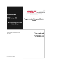
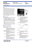
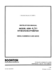
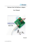
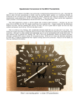
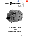
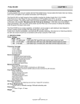
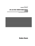
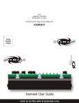
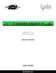
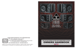
USER’S MANUAL STEP MOTOR DRIVERS MD10A, MH10 and MD125 OREGON MICRO SYSTEMS, INC. TWIN OAKS BUSINESS CENTER 1800 NW 169TH PLACE, SUITE C100 BEAVERTON, OR 97006 PHONE 503-629-8081 FAX 503-629-0688 COPYRIGHT NOTICE © 1993 Oregon Micro Systems, Inc. ALL RIGHTS RESERVED This document is copyrighted by Oregon Micro Systems, Inc. You may not reproduce, transmit, transcribe, store in a retrieval system, or translate into any language in any form or by any means, electronic, mechanical, magnetic, optical, chemical, manual, or otherwise, any part of this publication without the express written permission of Oregon Micro Systems, Inc. DISCLAIMER Oregon Micro Systems, Inc. makes no representations or warranties regarding the contents of this document. We reserve the right to revise this document, or make changes to the specifications of the product described within it at any time without notice and without obligation to notify any person of such revision or change. Revised May 26, 1993 TABLE OF CONTENTS 1. INTRODUCTION . . . . . . . . . . . . . . . . . . . . 1 2. LOCATION OF COMPONENTS . . . . . . . . . . 2 MOUNTING PLATE . . . . . . . . . . CONNECTOR . . . . . . . . . . . . . OPTION HEADER (MD125 ONLY) . . FAULT LED (MD125 ONLY) . . . . . . OFFSET TRIMPOTS (MD125 ONLY) 3. . . . . . . . . . . . . . . . . . . . . . . . . . . . . . . . . . . . . . . . . . . . . . 3 3 3 4 4 INSTALLATION . . . . . . . . . . . . . . . . . . . . . 5 POWER SUPPLY . . . . . . . . . . . . . . . SUPPLY GROUND . . . . . . . . . . . . . . LOGIC GROUND . . . . . . . . . . . . . . . PHASE OUTPUTS . . . . . . . . . . . . . . STANDBY CURRENT SET (MD125 ONLY) DIRECTION . . . . . . . . . . . . . . . . . STEP PULSE . . . . . . . . . . . . . . . . . +5 VOLT DC . . . . . . . . . . . . . . . . . CURRENT SET . . . . . . . . . . . . . . . . . . . . . . . . . . . . . . . . . . . . . . . . . . . . . . . . . . . . . . . . . . . . . 6 . 10 . 10 . 11 . 16 . 17 . 17 . 18 . 19 4. THERMAL DESIGN . . . . . . . . . . . . . . . . . . 24 5. MICROSTEPPING . . . . . . . . . . . . . . . . . . . 24 6. CURRENT PROFILE OPTION . . . . . . . . . . . 25 7. ELECTRONIC DAMPING (MH10 and MD125 ONLY) . . . . . . . . . . . . . . . . . . . . . . . . . . . . 26 VERY HIGH SPEED . . . . . . . . . . . . . . . . . . . 27 VERY LARGE INERTIAL LOAD . . . . . . . . . . . . 27 8. RESOLUTION SELECTOR (MD125 ONLY) . . . 28 9. MICROSTEP COMPENSATION (MD125 ONLY) 29 RESET METHOD . . . . . . . . . . . . . . . . . . . . 29 RUN METHOD . . . . . . . . . . . . . . . . . . . . . . 30 Driver User's Manual i 10. POWER-ON RESET (MD125 ONLY) . . . . . . . 30 11. UNDER-VOLTAGE LOCKOUT (MD125 ONLY) 30 12. FAULT LED (MD125 ONLY) . . . . . . . . . . . . . 31 13. CHOPPING FREQUENCY (MD125 ONLY) . . . 32 14. SPECIFICATIONS . . . . . . . . . . . . . . . . . . 33 15. LIMITED WARRANTY . . . . . . . . . . . . . . . . 35 16. RETURN FOR REPAIR PROCEDURES . . . 36 ii Driver User's Manual INTRODUCTION 1. INTRODUCTION The Oregon Micro Systems, Inc. (OMS) models MD10A, MH10 and MD125 microstepping motor driver modules are designed to run hybrid permanent magnet step motors. The MD10A can drive motors with current ratings between 0.75 and 7.2 amps per phase, while the MH10 can operate motors from 1.5 to 14 amps per phase. The MD125 is designed to run motors rated from .1 to 14 amps per phase. Motor current regulation is achieved by a high efficiency pulse width modulator (PWM) circuit using power MOSFETs. This results in a cooler running motor with less wasted energy. Microstepping is a major feature of these drivers. When driven by the MD10A or MH10, each motor step is divided into ten substeps called microsteps. As a consequence, a 200 step per revolution motor turns into a 2,000 step per revolution motor. For positioning applications this can mean a ten-fold improvement in resolution in the user’s system. The MD125 is a high resolution step motor driver featuring four user selectable microstep resolutions. The resolution is selected by an option header on the end of the drive. Available step rates are 10, 25, 50 and 125 microsteps per step. Other values are available as a custom made option. The MD125 is capable of delivering up to 1.5 million microsteps per second to the step motor. Microstepping reduces low speed motor vibration in addition to providing increased resolution. This is especially noticeable at speeds below 300 full steps per second. The step pulse rate going to the microstepping drivers will have to be higher in frequency than it would be for a full step drive to get the same angular move or RPMs. This would mean a step pulse generator would have to output 400,000 pulses per second to run the motor at 40,000 full steps per second, when the driver is set to 10 microsteps per step. The drivers operate on an unregulated positive supply voltage of +12VDC to +80VDC for the MD125 and +24VDC to +60VDC for the MD10A and MH10. When used with suitably sized motors, the drivers can provide over one-third horsepower (300 watts) to the user’s application. The drivers utilize all of the motor’s windings simultaneously instead of half of them as a conventional controller does. The result is a much cooler running motor. This allows the control to be tailored to the applicaDriver User's Manual 1 LOCATION OF COMPONENTS tion with a minimum of wasted energy. For low speed applications (0 to 5,000 full steps per second), the lower end of the power supply voltage range provides best performance, while the high end of the range is preferred for high speed (up to 40,000 full steps per second) operation. The control interface for the drivers is opto-isolated for maximum noise immunity. The inputs are compatible with TTL or open collector drivers and do not require additional components. Electronic damping circuitry is employed in the MH10 and MD125 to provide mid-band stability. This allows continuous, full power operation at speeds normally prohibited by mid-band resonance. A high efficiency ’H’ bridge output driver utilizes all MOSFET design to minimize heating due to switching losses. Automatic current standby in the MD125 reduces phase currents to a low level while the motor is at rest. This keeps heating of the drive and motor to a minimum. To improve motor efficiency the MD125 tracks the drive’s chopping frequency to the power supply volt age. This permits the use of motors with winding inductance as low as 1 millihenry, and provides better high speed performance. The MD125 features an electronic ’circuit breaker’ to protect the driver from dangerous conditions. Over-current (winding shorts, etc.), over-temperature (insufficient heat sinking), and undervoltage are sensed by the MD125. When any of these conditions occur the MD125 shuts down and turns on a ‘fault’ LED to indicate the presence of the fault condition. The drivers are compact, measuring 4" x 4.75" x .875". They come encapsulated in a heat conductive epoxy and encased in an anodized aluminum cover. The result is an environmentally rugged package that resists abuse and contamination. 2. LOCATION OF COMPONENTS The major components of the MD10A, MH10 and MD125 are shown in Figure 1. The following is a description of these components. 2 Driver User's Manual LOCATION OF COMPONENTS 5 2 1 4 3 Figure 1 MD125 COMPONENT LOCATION 2.1. MOUNTING PLATE The mounting plate of the driver also serves as a heat sink for the driver. All primary heat generating components are attached to this plate. Secondary heat generators are thermally coupled to it by the heat conductive epoxy used to encapsulate the drivers. 2.2. CONNECTOR A 12 position terminal strip located on the front edge of the driver provides the connections for power supply, motor windings and controller interface. The function of each contact is printed on the case adjacent to the terminal strip. Figure 2 shows a typical connection setup. 2.3. OPTION HEADER (MD125 ONLY) This 4 pin header is used to select microstep resolution. The user connects the appropriate pins with the shorting bars Driver User's Manual 3 LOCATION OF COMPONENTS Figure 2 MD10A CURRENT CONTROL supplied with the driver. Four resolutions are available in each driver. Refer to Section 8. for further details. 2.4. FAULT LED (MD125 ONLY) This LED indicates that the driver has triggered its protective shut down circuit. Cycling the power supply after correcting the fault condition will reset the MD125 and turn off the LED. Refer to Section 12. for further details. 2.5. OFFSET TRIMPOTS (MD125 ONLY) These two adjustment pots allow the user to trim the MD125 to a particular step motor. This nulls out any residual step error and is especially effective at microstep resolutions of 25 or above. 4 Driver User's Manual INSTALLATION Figure 3 MOTOR POWER SUPPLY 3. INSTALLATION Under most conditions the MD10A does not require a heat sink. It is sufficient to bolt it down to a chassis or metal plate in the user’s system using a thermal heat transfer compound. When operated at higher currents, the MH10 and MD125 require that an external heat sink be attached to the mounting plate. Optional heat sink kits are available from OMS as model number HS10. Refer to Section 4. for more detailed instructions regarding thermal design. No terminals or connectors are required on the wiring to the driver. A wire size of 16-22 gauge is recommended. Either stranded or solid conductor wire may be used. The insulation should be stripped back .25 inches and the wire left untinned. The following section describes each connector terminal in detail. The small size of these driver modules and absence of any adjustments allows them to be mounted in locations too small or too inaccessible for other drivers. Driver User's Manual 5 INSTALLATION 4 AMP/PHASE RADIDSYN 34D-9208 MOTOR 1.5 A. 24 V. 40 V. 6 0 V. 1.0 A. 0.5 A. 10K 20K 30K FULL STEPS PER SECOND Figure 4 POWER SUPPLY CURRENT VS. SPEED 3.1. POWER SUPPLY Terminal 1 is the ground connector. Terminal 2 connects to the positive output from the power supply. The power supply voltage for the MD10A and MH10 is +24VDC to +60VDC; the MD125 is +12VDC to +80VDC. The power supply may be unregulated; a transformer, bridge rectifier and filter capacitor are sufficient. For unregulated supplies it is recommended that the ripple voltage be limited to a maximum of 10% of the DC output voltage. All low level voltages are generated internally, so only a single voltage power supply is needed. The drivers will cease to function normally at voltages below +24VDC for the MD10A and MH10 and +12VDC for the MD125. If a low voltage, unregulated power supply is used be sure the ripple voltage does not drop below this voltage. 6 Driver User's Manual INSTALLATION CAUTION The power supply terminals should have a capacitor of at least 470 µ f connected across them. This is particularly important for regulated power supplies since they usually have little output capacitance. This capacitor should be located as close to terminals 1 & 2 as possible (see Figure 3, C2). For those users that wish to build their own power supply, Figure 3 shows a suggested circuit. Because of the electrical noise generated by these drivers, it is not recommended to share the power supply with low level logic circuitry. The power supply voltage must never exceed +60VDC for the MD10A and MH10 or +80VDC for the MD125. During rapid deceleration of large inertial loads from high speeds, step motors become generators of considerable electrical power. This is returned to the supply by the step motor driver. If the supply cannot absorb this power, the voltage generated may exceed the +60VDC limit of the MD10A and MH10 or the +80VDC limit of the MD125 and damage the driver and power supply. To guard against this problem a zener diode should be connected from terminal 2 to ground (Figure 3, D5). This diode protects the driver from any over-voltage condition. Recommended diodes for the MD10A and MH10 are 1N4762 (1 watt) or 1N5375 (5 watt). Recommended diodes for the MD125 are 1N4764 (1 watt) and 1N5378 (5 watt). Note the 5 amp fuse (F1) placed in series with terminal 2 and the power supply. In the event of an over-voltage condition the zener diode and fuse may be destroyed, but the driver and power supply will be protected from damage. The choice of a power supply voltage is determined primarily by the maximum speed of the motor and the allowed motor heating. Higher power supply voltages yield higher maximum operating speeds, and also hotter running motors. Generally, Driver User's Manual 7 INSTALLATION the power supply voltage should be high enough to meet the user’s speed requirements and no higher. Any voltage above that causes the motor to run hotter than necessary at any speed. The power supply current requirements are going to be at a maximum when the motor is running at the maximum possible speed or delivering torque just short of stalling. Power supply current requirements depend on the motor being used and whether it is wired for high performance (parallel) or low performance (series) operation. If the motor is wired for high performance (parallel) the current required from the supply will not exceed 2/3 of the motor’s rated per phase current. Low performance (series) operation requires a maximum of 1/3 the motor’s rated current. In other words, a motor rated at 4 amps per phase will need a power supply current of only 1.33 amps when connected in the series connection. That same motor when stopped will need less than 1/2 amp from the power supply. The current requirements for a motor at a given speed decrease with increasing power supply voltage. The actual current draw from the power supply also depends on the motor’s efficiency. Use the motor manufacturer’s phase current rating of the motor in conjunction with the motor wiring option (series or parallel) to estimate the size of power supply required. As an example, assume a 6 wire motor rated at 4 amps per phase is to be used with the power supply circuit (in Figure 3) and the motor will be used in the full winding (series) configuration. The following equation estimates the current required from the power supply: Isupply= 1 (4) = 1.33 amps 3 In this example, assume a transformer with a +25VDC RMS secondary will be used. After rectification this will produce approximately +37VDC power supply voltage. To calculate the size of the filter capacitor (Figure 3, C1): C1 = 83333 ∗ 8 isupply 1.33 = 83333 ∗ = 3000 µf vsupply 37 Driver User's Manual INSTALLATION POWER SUPPLY 30 VDC 1.8 A/PHASE - 23D6204 4.0 A/PHASE - 34D9208 7.0 A/PHASE - 34D9214 2.41 A at 24K 7 A/PHASE 2.5 A. 2.0 A. 1.5 A. 1.33 A. at 18.8K 4 A/PHASE 1.0 A. 0.66 A. at 18K 1.8 A/PHASE 0.5 A. 10K 20K 30K FULL STEPS PER SECOND Figure 5 MOTOR POWER SUPPLY CURRENT C2 (in Figure 3) is the 470 µf capacitor that should be located close to the driver power supply terminals. C1 may be made smaller by that amount or 2500 µf, if desired. Both capacitors must have a voltage rating safely in excess of the power supply voltage; +50VDC being a good choice for this example. More than one driver can be run from a common power supply if the filter capacitor is sized large enough to account for the combined load. Each driver must have separate leads back to the power supply. The curves shown in Figure 4 show the power supply current versus speed of a typical 4 amp per phase motor driven by the MD10A. The curves apply for power supply voltages of +24VDC, +40VDC and +60VDC. The motor ran unloaded. Note, that regardless of power supply voltage, the motor never draws more than 1.33 amps from the power supply. At any given speed the motor requires less current with increasing power supply voltage. The curves shown in Figure 5 show the power supply current versus speed for low, medium and high current step motors. Driver User's Manual 9 INSTALLATION POWER SUPPLY = 30 V. RAPIDSYN 23D-6204 MOTOR 1,8 A 100 90 80 SHAFT HORSEPOWER TORQUE 70 60 0.02 HP 50 40 0.01 HP 30 20 10 20 50 100 200 500 1K 2K 5K 10K 20K FULL STEPS PER SECOND Figure 6 MOTOR TORQUE VS. SPEED The motors are run unloaded and the power supply voltage is +30VDC in each case. Note the stall currents for each motor are approximately 1/3 the motor’s rated per phase current. At speeds below stall, the difference between the running current and that motor’s stall current is an indication of the reserve torque at any given speed. Figure 6 demonstrates the motor torque and power output versus speed for a typical motor. 3.2. SUPPLY GROUND Motor power supply return (pin #1) or ground. This terminal is also connected internally to the logic ground terminal (pin #12). 3.3. LOGIC GROUND This terminal (pin #12) should be used for the low level logic return or ground. It is the same potential as supply ground (pin #1) and is provided as a user convenience. If the logic ground 10 Driver User's Manual INSTALLATION is connected to the power supply ground elsewhere in the user’s system, then it is not necessary to use this terminal. To ensure isolation from the host computer this connection should NOT be connected to the step pulse source board. The cable shield should be grounded at load end and left open at the source. 3.4. PHASE OUTPUTS These are the phase winding outputs to the step motor. One motor winding goes to phase A-B and the other motor winding connects to phase C-D. The drivers will drive 4, 6 and 8 wire motors. With 6 wire and 8 wire motors, the user has the option of connecting the windings in a high or low performance configuration. 4 wire motors are treated as the high performance configuration. The high performance configuration in a 6 wire motor is called half winding or parallel operation. Half winding operation uses the center-tap wire and one end wire to constitute a winding (Figure 8). The other end wire of each winding is not used. In an 8 wire motor the windings are connected as pairs of parallel wired windings. The low performance configuration in a 6 wire motor is called full winding or series operation. Only the end wires of each phase constitutes a winding (Figure 7). The center-taps are left unused. In an 8 wire motor the windings are connected as pairs of series wired windings. Table 1 and Table 2 show various manufactures’ 6 wire motor lead color codes and how they connect to the driver for full winding and half winding operation. Table 3 and Table 4 show various manufacturers’ 8 wire motor lead color codes and how they connect to the driver for series and parallel wired operation. Note that the wires in parentheses are connected to each other and not to a terminal on the driver. Wires not connected should not be left exposed. Cut off the stripped ends and insulate them with electrical tape or heat-shrink tubing. These drivers use high frequency switching type techniques. Because of the rapid rate of voltage and current change inherent with this type of driver, considerable RFI is generated. Driver User's Manual 11 INSTALLATION The following precautions should be taken to prevent noise from coupling back to the inputs and causing erratic operations. 1. Never run the motor leads in the same cable or wiring harness as the step, direction or +5VDC input lines. 2. Keep power supply leads as short as possible. If the power supply lead length exceeds 12 inches, use a .1 µf capacitor across terminals 1 & 2 at the drive. 3. Never wire capacitors, inductors or any other components to the motor output terminals. 4. Ground the case of the driver. 5. Ground the step motor case. CAUTION: The motor should never be disconnected from the driver while power is applied. The large voltage transients developed by the collapsing magnetic field in the motor will destroy the power MOSFETs. The connection of zeners back to back across the driver outputs, as shown in Figure 2, will help protect the driver if the motor is accidentally disconnected. 12 Driver User's Manual INSTALLATION Figure 7 FULL WINDING OPERATION Table 1 FULL WINDING OPERATION MANUFACTURER Superior Electric 3 grn/white MOTOR TERMINAL 4 5 green red/white Rapidsyn IMC Eastern Air Devices Pacific Scientific Warner Electric Vexta Japan Servo MEA/Digital Motor grn/white grn/white grn/white black brown blue blue black green green green orange orange red red orange Driver User's Manual red/white red/white red/white red red black yellow red 6 red red red red yellow yellow green green yellow 13 INSTALLATION Figure 8 HALF WINDING OPERATION Table 2 HALF WINDING OPERATION MANUFACTURER Superior Electric Rapidsyn IMC Eastern Air Dev. Pacific Scientific Warner Electric Vexta Japan Servo 3 white white white white black black blue blue MOTOR TERMINAL 4 5 green black green black green black green black org/black red orange red white yellow white* white* 6 red red red red red/yellow white green green * White wires are not interchangeable, use an Ohm meter to find white-blue and white-green pairs. 14 Driver User's Manual INSTALLATION Table 3 SERIES WINDING OPERATION MANUFACTURER Superior Electric Pacific Scientific Bodine Portescap MEA/Digital Motor 3 MOTOR TERMINAL 4 5 6 red red/white green green/white (black-white) (orange-black/white) black orange red yellow (black/white-org/white) (red/white-yellow/white) brown orange red yellow (brown/white-org/white) (red/white-yellow/white) brown org/white red yell/white (brown/white-orange) (red/white-yellow) black orange red yellow (black/white-org/white) (red/white-yellow/white) Table 4 PARALLEL WINDING OPERATION MANUFACTURER Superior Electric Pacific Scientific Bodine Portescap MEA/Digital Motor Driver User's Manual 3 red white black org/white brown org/white brown orange black org/white MOTOR TERMINAL 4 5 6 black green orange red/white black/white green/white black/white red red/white orange yell/white yellow brn/white red/white red orange yellow yell/white brn/white red red/white org/white yellow yell/white black/white red red/white orange yell/white yellow 15 INSTALLATION 3.5. STANDBY CURRENT SET (MD125 ONLY) This output implements the automatic standby feature of the MD125. By reducing the phase current to a lower, ‘standby’ level the drive system operates cooler during periods of motor inactivity. Heating of the motor, drive and power supply are kept to a minimum by utilizing this option. The amount of current reduction is adjustable from 0 to 100 percent of normal operating current. A resistor is connected from the standby set output to the current set input (terminal 7 to terminal 11) to set the current reduction. The value of the standby set resistor is calculated from the following two equations: R parallel = 47000 ∗ istandby 7.2 − istandby Where R parallel is the resistance required at terminal 11 to set the desired standby current, Istandby. This is the parallel combination of the existing current set resistor R, and the yet to be calculated standby current set resistor Rstandby Rstandby= rparallel ∗ rset rset − r parallel Where R standby is the resistor that will go between terminal 7 and terminal 11. Negligible power is involved; so a 1/4 watt resistor may be used. When the motor has stopped for more than 1 second, the standby current set output grounds R standby effectively placing it in parallel with R set. This lowers the total resistance at the current set input terminal which lowers the phase current. Motor phase currents are restored to their normal level 2 milliseconds after the next step pulse is received. If there is less than 1 second between step pulses, normal running current will always be maintained. If 100% of normal current is desired during standby, the standby current set output is not connected. If 0% of normal current is desired (freewheeling), short terminal 7 to terminal 11. 16 Driver User's Manual INSTALLATION 3.6. DIRECTION Terminal 8 is the direction input. This input is sampled by the driver on every step pulse input to determine which direction the motor will move. The setup time for this input is 10 microseconds, i.e. the direction input must be correct 10 µS before the step pulse is issued. If the direction input is changed simultaneously with the low to high transition of the step pulse the direction will not change until the next step pulse. The drivers employ an opto-coupler to isolate the direction input from the driver’s power supply. The user must provide a +5VDC supply to operate the opto-coupler circuit. This permits the use of current sink drivers, such as TTL logic or open collector transistors, to operate the input. The current requirement is 16 milliamps, which is compatible with standard TTL outputs. The logic level on this input may be changed at any other time as often as the user wishes. No motor motion will result until a step pulse is applied, then the direction of the motor for that microstep will be set by what logic was present at the moment the step edge occurred. 3.7. STEP PULSE Microstepping in the MD125 occurs on both edges of the step pulse input. This is done to improve motor smoothness at low speeds. The current is changed in the phase A-B motor winding on the leading edge of the step pulse. The current is changed in the phase C-D motor winding on the trailing edge of the step pulse. The result is a smoothness equivalent to a driver having twice the microstep resolution. This improvement comes for free, since the pulse rate is half of what would normally be required to achieve a given level of smoothness. The effect is most pronounced when the input is driven by 50% duty cycle pulses. The improvement is negligible when driven by very narrow (low duty cycle) pulses. The step input is opto-isolated like the direction input described above. The minimum on or off time is 300 nanoseconds. In the MD10A and MH10, the step pulse (pin #9) input causes the step motor to move one step (microstep) for each input pulse. Driver User's Manual 17 INSTALLATION The direction of the move is set by the logic level on the direction input. The step pulse rise and fall times for this input should each be less than 1 microsecond, otherwise more than one microstep per step pulse may occur. 3.8. +5 VOLT DC This terminal (pin #10) requires +5VDC from an external source to power the emitter diode in the opto-isolators in the drivers. CAUTION Do not attempt to operate the drivers without a current set resistor if the mo tor rating is below the maximum rating of the driver. All models of the drivers default to their maximum current and can damage motors with current ratings substantially less than this current level. This is the common anode terminal for the step pulse and direction opto-coupler LEDs. An external +5VDC supply is connected to this terminal to provide the source of LED current for the step pulse and direction inputs. If both are on, 32 milliamps of current is required from the +5VDC supply. If power supply voltages higher than +5VDC must be used, the step pulse and direction inputs require additional series resistance to limit currents to 16 milliamps. The following equation determines the value for these resistors: R= 18 V − 1.5 − 180 0.016 Driver User's Manual INSTALLATION For example, if a +12VDC supply is to be used: R= 12 − 1.5 − 180 = 656.25 − 180 = 470 Ohms 0.016 Place 470 Ohm resistors in series with each input. CAUTION Do not put any resistors in series with the +5VDC terminal. 3.9. CURRENT SET This terminal (pin #11) is used to set the motor current level, matching the driver’s current supply capability to the needs of the user’s motor. A single 1/4 watt resistor connected between the current set terminal and logic ground is all that is required. The proper resistor value is selected from Table 5, Table 6 or Table 7. If a 6 or 8 wire motor is to be series connected use the series column, otherwise use the parallel column for parallel connected or 4 wire motors. The parallel column is the current actually delivered by the driver. The series column is provided for convenience in calculating the resistor value for the series connected case. Match the motor’s per phase current to the closest listed value, then pick the resistor value associated for that current. If the motor current falls between the table entries, then interpolate between the entries or use the larger of the two resistor values. Note that most motor manufacturers rate their motors in unipolar current per phase. These are bipolar drivers. The bipolar rating is √ 2 times the unipolar rating and the 2 √ bipolar series connection would use a current of times the 2 unipolar rating. Note that the factor of 2 is already taken into account in the series ratings in Table 6 and Table 7. Most motor data sheets specify the unipolar current rating. An optional use for the current set terminal is to set a lower, standby current while the motor is stopped, or shut off the motor current altogether. This is illustrated in Figure 2. A standby Driver User's Manual 19 INSTALLATION current can be set by switching another resistor in parallel with the current set resistor. The standby current will be equivalent to the resulting parallel-wired resistor. The following example will illustrate operating a 4 amp per phase motor at 1.5 amps standby: A 4 amp per phase motor needs a 68k current set resistor with the MD10A. To reduce the current to 1.5 amps per phase standby, the current set resistor must be the equivalent of 12k. The value of the resistor to be wired in parallel with the 68k current set resistor is calculated as follows: 68k X 12k / (68k - 12k) = 14.57k or 15k This resistor can be switched in or out with a relay, transistor or an open collector gate such as a 7406 or 7407. The motor can be shut off entirely by shorting the current set terminal to logic ground. This can also be done with a 7406 or 7407 TTL inverter as provided on the auxiliary output of the OMS controllers. If this is done, however, there will no longer be electrical isolation between the driver and the controller unless the opto-isolator is included, as shown in Figure 2. The maximum phase current is obtained with no current set resistor (terminal 11 voltage equals +2.5VDC). Zero phase current occurs with current set shorted to ground (terminal 11 voltage equals 0VDC). CAUTION These drivers default to their maximum per phase current if no current set resis tor is present. This may cause damage to a motor that is too small for this cur rent level. For best low speed smoothness, the motor phase current should not differ from the manufacturer’s rating by more than 20%. Currents substantially above or below this may affect microstep accuracy and increase low speed vibration. 20 Driver User's Manual INSTALLATION The current set input may also be driven by external circuitry such as operational amplifiers. In this case motor phase current is a linear function of the voltage on terminal 11. Exceeding +2.5VDC on terminal 11 may result in permanent damage to the driver. The current set input is used in conjunction with the standby current set input to provide current reduction while the driver is idle. See Standby Current Set (Section 3.5.) for details. Phase current reduction can also be achieved by switching in an external parallel resistance. The circuit in Figure 9 shows how optically isolated standby torque and freewheeling functions may be implemented. Figure 9 EXTERNAL CURRENT STANDBY Driver User's Manual 21 INSTALLATION Table 5 MD125 CURRENT SET RESISTOR VALUES MODE OF OPERATION HALF WINDING FULL WINDING (PARALLEL) (SERIES) 22 CURRENT SET RESISTOR STANDARD STANDARD 1% (OHMS) 5% (OHMS) 0.1A 0.2A 0.3A 0.4A 0.5A 0.6A 0.7A 0.8A 0.9A 1.0A 0.2A 0.4A 0.6A 0.8A 1.0A 1.2A 1.4A 1.6A 1.8A 2.0A 665 1.33K 2.05K 2.74K 3.48K 4.32K 5.11K 5.90K 6.65K 7.50K 680 1.3K 2.0K 2.7K 3.6K 4.3K 5.1K 6.2K 6.8K 7.5K 1.2A 1.4A 1.6A 1.8A 2.0A 2.2A 2.4A 2.6A 2.8A 3.0A 3.2A 3.4A 3.6A 3.8A 4.0A 4.2A 4.4A 4.6A 4.8A 5.0A 5.2A 5.4A 5.6A 5.8A 6.0A 6.2A 6.4A 6.6A 6.8A 7.0A 2.4A 2.8A 3.2A 3.6A 4.0A 4.4A 4.8A 5.2A 5.6A 6.0A 6.4A 6.8A 7.2A 7.6A 8.0A 8.4A 8.8A 9.2A 9.6A 10.0A 10.4A 10.8A 11.2A 11.6A 12.0A 12.4A 12.8A 13.2A 13.6A 14.0A 9.31K 11.3K 13.3K 15.8K 18.2K 21.0K 23.7K 26.7K 30.1K 33.2K 37.4K 42.2K 47.5K 52.3K 59.0K 66.5K 73.2K 82.5K 93.1K 107K 121K 140K 165K 196K 237K 294K 374K 517K 806K 1.6 M 9.1K 11K 13K 16K 18K 22K 24K 27K 30K 33K 36K 43K 47K 51K 62K 68K 75K 82K 91K 110K 120K 150K 160K 200K 240K 300K 360K 510K 820K 1.6 M Driver User's Manual INSTALLATION Table 6 MD10A CURRENT SET RESISTOR VALUES MODE OF OPERATION Full Winding (Series) 1.5 2.0 2.5 3.0 3.5 4.0 4.5 5.0 5.5 6.0 6.5 7.0 Half Winding (Parallel) 0.75 1.0 1.25 1.5 1.75 2.0 2.25 2.5 2.75 3.0 3.25 3.5 CURRENT SET RESISTOR Standard 5% (Ohms) 12K 15K 27K 33K 47K 68K 82K 120K 180K 270K 360K 1.3M Table 7 MH10 CURRENT SET RESISTOR VALUES MODE OF OPERATION Full Winding (Series) 3.0 4.0 5.0 6.0 7.0 8.0 9.0 10.0 11.0 12.0 13.0 14.0 Driver User's Manual Half Winding (Parallel) 1.5 2.0 2.5 3.0 3.5 4.0 4.5 5.0 5.5 6.0 6.5 7.0 CURRENT SET RESISTOR Standard 5% (Ohms) 12K 15K 27K 33K 47K 68K 82K 120K 180K 270K 360K 1.3M 23 THERMAL DESIGN 4. THERMAL DESIGN The MD10A does not need additional heat sinking under most conditions. The driver uses high efficiency power MOSFETs as output drivers and low power CMOS logic to minimize internal heat generation. What heat is generated is easily conducted to the aluminum case of the MD10A by a heat conductive epoxy used as an encapsulant. The major sources of heat, the output drive MOSFETs, are mounted on a heavy gauge aluminum base plate which serves as a mounting plate as well as a heat spreader. The MH10 and MD125, because of their higher current, may require an external heat sink. To determine if the available heat sinking is sufficient, allow the driver five minutes to warm up with motor connected but not stepping. This operating condition causes the maximum amount of heat to be dissipated by the driver. After five minutes touch the driver. If it is hot to the touch, it is too hot and needs a better heat sink. The available heat sinking may be enhanced by mounting the MD10A on a metal surface, preferably aluminum, in the user’s system such as a panel or chassis. If the mounting surface is painted, the paint may be removed to expose bare metal to the base plate. Should these measures prove to be insufficient or impractical, the most effective solution is to mount the driver on a heat sink such as the OMS HS10. For best thermal conduc tivity use heat sink compound between the finned sink and the mounting plate of the driver module. 5. MICROSTEPPING Microstepping is a technique that electronically multiples the number of steps a motor takes per revolution. This is useful because it increases motor angular resolution and decreases motor vibration. The MD10A and MH10 divide each motor step into ten smaller sub-steps called microsteps. Every step pulse input causes the motor to move one microstep, taking ten pulses to move the equivalent of one full step. The four multipliers available on the MD125 are 10, 25, 50, and 125. A 200 step per revolution motor, operated at 125 microstep resolution, will take 25,000 steps to complete one revolution of the motor shaft. 24 Driver User's Manual CURRENT PROFILE OPTION Microstepping is normally accomplished by driving the motor windings with sine and cosine weighted currents. A 90 degree electrical angle change in these currents results in a mechanical angle movement of 1.8 degrees (one full step) in a 200 step/revolution motor. The sine-cosine values may be replaced with values compensated for a specific motor type or characteristic (see Current Profile Option, Section 6.). Further references in this section to ‘sine’ or ‘cosine’ make no further distinction between true sine-cosine values and any compensated curve that may have been selected. Low speed vibration results from the start-stop or incremental motion of the motor. This generates periodic acceleration and deceleration reaction torques at the step rate. When the step rate matches, or is a sub-harmonic of the mechanical resonant frequency of the motor, the vibrations become severe. Microstepping divides full step positioning into small ‘microsteps’, thus decreasing the magnitude of the reaction torques generated. This results in a commensurate decrease in vibration. Another benefit of microstepping is an increase in the number of resolvable angular positions. However, there are a number of factors which limit the achievable open-loop accuracy of these positions. See Current Profile Option (Section 6.) for further details. 6. CURRENT PROFILE OPTION Microstepping is achieved by varying the currents in the motor’s phase windings in a continuous and cyclic manner. Sine-cosine weighed currents provide the first approximations of a linear relationship between the (electrical) angle of the phase currents and the (mechanical) angle of the motor. Most step motors have a residual non-linearity in the electrical to mechanical angle function. This means a microstep taken near the motor’s fullstep location will not have the same angular displacement as one taken near the half-step location. This trait is specific to a motor or model. The non-linearity can be canceled by distorting the sine-cosine currents to match the characteristics of the motor. This compensated current profile may be substituted for the standard sinecosine profile in the internal ROM. For a nonrecurring engineering fee, OMS will generate a profile tailored to a cus Driver User's Manual 25 ELECTRONIC DAMPING (MH10 and MD125 ONLY) tomer submitted motor. The result is the highest obtainable open loop position accuracy for that motor. The microstep resolutions for compensated profiles are the same as those available for the standard sine-cosine version of the driver. It is also possible to order an MD125 with different current profiles at the same microstep resolution. The option head would then choose between motor types rather than reso lutions. 7. ELECTRONIC DAMPING (MH10 and MD125 ONLY) Most step motors are prone to parasitic instability or resonance when rotating at a rate of 4 to 15 revolutions per second. Called mid-band instability or resonance, the phenomenon manifests itself as a torsional oscillation of 50 to 150 Hz when the motor is running in this speed range. The torsional oscillation has a tendency to increase in amplitude with time until it reaches a peak equal to the step angle. When this happens, the motor loses synchronization and stops. Generally the amplitude buildup takes from tens to hundreds of cycles to reach this level, so several seconds may elapse from the start of the oscillation until the motor stops. Usually this is long enough to allow the motor to accelerate through this region. However, continuous operation in this speed band is impossible. Above and below this range of speeds, the oscillation amplitude may not be sufficient to stop the motor but it is still present. Figure 10 shows the parametric resonance frequency versus motor step rate for three unrelated step motors. In all three cases resonance breaks out at 5 to 7 revolutions per second and is most severe at the higher torsional frequencies (lowest step rates). Because any torsional oscillation implies acceleration and deceleration of a mass, torque that otherwise would have been available for useful work, is wasted to sustain this oscillation. The MD125 and MH10 incorporate a mid-band electronic damping compensation circuit that closes the loop on this instability and electronically damps it out. Since the motor is now unable to sustain oscillation, torque previously wasted is now available. With electronic damping circuitry the motor may be run continuously at speeds where de-synchronization would otherwise oc 26 Driver User's Manual ELECTRONIC DAMPING (MH10 and MD125 ONLY) cur. The motor no longer exhibits ‘forbidden’ regions where continuous-operation cannot be sustained and there is more torque available over the entire operating range of the driver. The operation of the electronic damping circuit in most applications is transparent to the user, in the sense that no special provisions have to be taken to accommodate it. There are two instances where electronic damping may not be advantageous: 7.1. VERY HIGH SPEED The electronic damping circuit limits the maximum speed to 50,000 full steps per second. Should it be necessary to run the motor faster than that, up to 100,000 full steps per second, a special ‘electronic damping disabled’ version of the MD125 or MH10 can be ordered (a Superior Electric ME 61-8001 will exceed 150,000 full step per second or 45,000 RPM). 7.2. VERY LARGE INERTIAL LOAD Microstepping permits reliable operation with inertial loads in excess of 100 times the motor’s moment of inertia. However, Superior MO62-FD04 150 Hz. Rapidsyn 34D-9208A 100 Hz. 50 Hz. Sigma 20-22350-26175 5 khz. 10 khz. Full steps/second Figure 10 RESONANCE Driver User's Manual 27 RESOLUTION SELECTOR (MD125 ONLY) very large inertial loads so lower the mechanical resonant frequency that the electronic damping circuits may cause oscillation. It may be better to order the drive without the circuit since it is usually not a problem with moderate to large inertial loads anyway. 8. RESOLUTION SELECTOR (MD125 ONLY) The option header is used to select the microstep resolution of the MD125 (see Figure 11). The bottom two header pins are connected to ground. By selectively shorting the upper pins to the grounding pins, one of the drive’s four microstep resolution is selected. To select a microstep resolution, use the supplied shorting bars in the following manner. As well as choosing the step resolutions available in the driver, the user may specify the phase current profile for each selection. This is done to compensate for non-linearity in microstep step size at high resolutions. For more information, see Current Profile Option (Section 6.) . 10 microsteps/step 25 microsteps/step 50 microsteps/step 125 microsteps/step Figure 11 STANDARD MD125 RESOLUTION OPTIONS 28 Driver User's Manual MICROSTEP COMPENSATION (MD125 ONLY) 9. MICROSTEP COMPENSATION (MD125 ONLY) The offset trimpots provide compensation for the distortion that occurs to microstep size near the half-step location. Residual full step cyclic errors, a function of power supply voltage, motor phase inductance and phase current magnitude, cause the uneven microstep size. These errors can be canceled by introduc ing an offset voltage with the offset trimpots. The magnitude of the untrimmed error is on the order of 1/16 of a full step, so it is unlikely to be noticeable at resolutions less than 16 microsteps. Trimming is unnecessary at resolutions below 10 microsteps. Compensation is disabled at the halfscale position of the trimpot. The screwdriver slot in the trimpot is vertical at the half-scale position. Each phase winding has its own associated error component so two trimpots are required. The left trimpot compensates the phase A-B outputs while the right trimpot compensates the phase C-D outputs. There are two methods for trimming the MD125 to a motor and power supply. Both methods require the motor and power supply to be connected to the MD125. 9.1. RESET METHOD The reset method depends on the MD125’s power-on reset behavior, i.e. the driver does not apply power to the motor windings until a step pulse is received. Any holding torque the motor has when powered up is due to offset errors. This may be compensated as follows. 1. Turn both trimpots to the midrange position. 2. Turn on the power. 3. Adjust left trimpot for minimum holding torque. 4. Adjust right trimpot for minimum holding torque. Driver User's Manual 29 POWER-ON RESET (MD125 ONLY) 9.2. RUN METHOD The run method depends on trimming out vibration; the observable manifestation of offset errors. This requires a 250 Hz source connected to the step pulse input. A function generator set to +5 and -5 voltage levels or any OMS indexer are suitable for this purpose. 1. Set both trimpots to mid-scale. 2. Turn on the power, apply the 250 Hz source (JG250 from OMS indexer). 3. Adjust the left trimpot for minimum vibration. 4. Adjust right trimpot until all vibration stops. 10. POWER-ON RESET (MD125 ONLY) The power-on reset circuitry of the MD125 ensures that the driver turns on in an organized manner. All internal counters and other circuits are held in a reset state until the power supply voltage rises to a safe operating level. The threshold for operation is +11.75VDC. Power-on reset is released on the first step pulse after the power supply rises above this threshold. Until receipt of the first step pulse the motor windings carry no current and the motor has no holding torque. The phase outputs are active however, and carry a high frequency square-wave equal in voltage to the power supply. After receiving the first pulse, the driver delivers full holding torque and the motor is located at the first microstep position; phase A-B outputs are at maximum current while phase C-D outputs are at minimum current. 11. UNDER-VOLTAGE LOCKOUT (MD125 ONLY) Under-voltage lockout protects the MD125’s output transistors from damage resulting from low power supply voltage. This feature activates when the power supply voltage drops below +11.75VDC. Below this voltage, the phase outputs (terminals 3, 4, 5, 6) are pulled low. Supply current is removed from the output transistors and the motor stops positioning. When the power 30 Driver User's Manual FAULT LED (MD125 ONLY) supply voltage falls below +5VDC, the phase outputs go open circuit and float. While the MD125 is in an under-voltage condition, the driver is held in the reset state. Once the power supply voltage rises above +11.75VDC and all internal voltages have stabilized to their proper levels, a power-on reset is automatically executed. 12. FAULT LED (MD125 ONLY) The MD125 incorporates protective circuitry to guard the drive against potentially destructive conditions. An electronic ’circuit breaker’ is tripped when fault conditions are sensed. The fault LED illuminates to indicate that the MD125 has shut down. This may be due to either an over-temperature or an over-current condition. While shut down, the motor phase current outputs (terminals 3, 4, 5, 6) are all taken to 0VDC. This action removes all current from the motor windings, thus protecting the output transistors. Though no power supply current flows, the motor is difficult to turn because the windings are shorted together. All internal circuits are held in a reset condition to minimize the quiescent current draw of the driver. This keeps power dissipation to a minimum, allowing the fastest possible cooling of the driver. Power supply voltage must be removed and reapplied to reset the ’circuit breaker’ and extinguish the fault LED. The MD125 has a sensor which trips the protection circuit when the case temperature exceeds 75 C. The driver will not operate after it has cooled down. The power supply must be ‘recycled’ to operate the driver. If the MD125 has shut down because of overheating, the cause is usually an inadequate heat sink. The other cause of protective shut down is an over-current condition. The MD125 will shut down on phase output to ground shorts, phase to phase shorts (shorted windings), cross-wired windings and windings with insufficient inductance (shorted turns). The over-current sensor trips the protection circuit any time a phase output current exceeds 10 amps for 2 µS. This rapid response to over-current conditions ensures the safety of the phase output transistors. Once shut down, the MD125 will not operate, even if the fault condition has cleared. The power supply must be recycled to deactivate the protection circuit. If Driver User's Manual 31 CHOPPING FREQUENCY (MD125 ONLY) the MD125 has shut down due to an over-current condition, determine the cause and correct it before recycling the power supply, otherwise it will simply shut down again. Overheating shut downs can be distinguished from over-current shut downs by observing the case temperature of the MD125. Over-current conditions will shut down the drive before high case temperatures can occur. If the MD125 repeatedly shuts down and the cause is not obvious, change motors. The cause may be an inter-winding short. 13. CHOPPING FREQUENCY (MD125 ONLY) To improve motor efficiency, the MD125 automatically adjusts its chopping frequency to be proportional to power supply voltage. This means the motor ripple current is independent of power supply voltage. Motor hysteresis losses are reduced and less motor heating results. Because of this, a very low inductance motor may be used, yielding better high speed performance. The chopping frequency is 1 khz per volt in the MD125. The chopping frequency ranges from 12 khz to 80 khz over the entire power supply range. The minimum recommended motor winding inductance is 500 microhenrys. Consult OMS about operation of motors with less than 500 µH of inductance. 32 Driver User's Manual SPECIFICATIONS 14. SPECIFICATIONS Table 8 MICROSTEPPING MOTOR DRIVES MODEL STEPS/STEP CURRENT PER PHASE ELECTRONIC DAMPING MD10A 10 .75 to 3.6 amp NO MD10A-C8 10 .75 to 3.6 amp NO MH10 10 1.5 to 7.2 amp YES MD125 10/25/50/125* .1 to 7.2 amp YES HS10 Companion Heat Sink *Other resolutions available on special order. Table 9 GENERAL MD10A AND MH10 Resolution 10 microsteps/step Supply Voltage 24 to 60 VDC Current (no motor) 60 ma typical PWM Frequency (MD10A and MH10) 20 khz typical PWM Frequency (MD10A-C6) 54 to 72 khz Motor Current (MD10A) .75 to 3.6 amp/phase Motor Current (MH10) 1.5 to 7.2 amp/phase Driver User's Manual 33 SPECIFICATIONS Table 10 GENERAL MD125 Resolution 10, 25, 50, and 125 microsteps/step Supply Voltage 12 to 80 VDC Current (no motor) 60 ma typical PWM Frequency 12 to 80 khz Motor Current .1 to 7 amp/phase Table 11 STEP PULSE INPUT Voltage 0 to 5.0 VDC Logic ‘1’ Voltage 1.8 VDC minimum Logic ‘0" Current 12 to 20 ma Pulse Width ‘High’ (MD10A and 1 uSec minimum MH10) Pulse Width ‘High’ (MD125) 0.3 uSec minimum Pulse Width ‘Low’ (MD10A and 1 uSec minimum MH10) Pulse Width ‘Low’ (MD125) 0.3 uSec minimum Step Pulse Frequency (MD10A and 500 khz maximum MH10) Step Pulse Frequency (MD125) 1500 khz maximum Table 12 DIRECTION INPUT Voltage 0 to 5.0 VDC Logic ‘1’ Voltage 1.8 VDC minimum Logic ‘0’ Current 12 to 20 ma 34 Driver User's Manual LIMITED WARRANTY Table 13 ENVIRONMENTAL Operating Temperature -20 to +75 degrees Centigrade Humidity 0 to 95% Shock 30 G Table 14 MECHANICAL Weight 20 oz. maximum Mounting Screw Size #6 to #8 Size 4.75 x 4.0 x 0.83 inches high Mounting Hole Centers 3.625 x 3.625 inches 15. LIMITED WARRANTY The Seller warrants that the articles furnished are free from defect in material and workmanship and perform to applicable, published Oregon Micro Systems, Inc. specifications for one year from date of shipment. This warranty is in lieu of any other warranty express or implied. In no event will Seller be liable for incidental or consequential damages as a result of an alleged breach of the warranty. The liability of Seller hereunder shall be limited to replacing or repairing, at its option, any defective units which are returned f.o.b. Seller’s plant. Equipment or parts which have been subject to abuse, misuse, accident, alteration, neglect or unauthorized repair are not covered by warranty. Seller shall have the right of final determination as to the exist ence and cause of defect. As to items repaired or replaced, the warranty shall continue in effect for the remainder of the warranty period, or for 90 days following date of shipment by Seller of the repaired or replaced part whichever period is longer. No liability is assumed for expendable items such as lamps and fuses. No warranty is made with respect to custom equipment Driver User's Manual 35 RETURN FOR REPAIR PROCEDURES or products produced to Buyer’s specifications except as specifi cally stated in writing by Seller and contained in the contract. 16. RETURN FOR REPAIR PROCEDURES 1. Call Oregon Micro Systems Customer Service at 503-6298081. 2. Explain the problem and we may be able to solve it on the phone. If not, we will give you a Return Materials Authorization (RMA) number. Mark the RMA number on the shipping label, packing slip and other paper work accompanying the return. We cannot accept returns without an RMA number. 3. Please be sure to enclose a packing slip with the RMA number, serial number of the equipment, reason for return, and the name and telephone number of the person we should contact if we have further questions. 4. Pack the equipment in a solid cardboard box secured with packing material. 5. Ship prepaid and insured to: OREGON MICRO SYSTEMS, INC. Twin Oaks Business Center 1800 NW 169th Place, Suite C100 Beaverton, OR 97006 36 Driver User's Manual