1
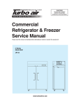
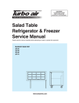
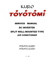
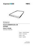
Commercial
Refrigerator & Freezer
Service Manual
Top mount
Model No.: PRO-26R
PRO-26-2R
PRO-50R
PRO-50-4R
PRO-77R
PRO-77-6R
2
PRO-26F
PRO-26-2F
PRO-50F
PRO-50-4F
PRO-77F
PRO-77-6F
TABLE OF CONTENTS
1. FEATURE CHART
1-1.FRONT VIEW/PLAN VIEW (1DDOR):PRO-26R PRO-26F PRO-26-2R PRO-26-2F
1-2.FRONT VIEW/PLAN VIEW (2DDOR):PRO-50R PRO-50F PRO-50-4R PRO-50-4F
1-3.FRONT VIEW/PLAN VIEW (3DDOR):PRO-77R PRO-77F PRO-77-6R PRO-77-6F
2. WIRING DIAGRAMS
2-1. 1DDOR:PRO-26R PRO-26F PRO-26-2R PRO-26-2F
2-2. 2DDOR:PRO-50R PRO-50F PRO-50-4R PRO-50-4F
2-3. 3DDOR:PRO-77R PRO-77F PRO-77-6R PRO-77-6F
3. PART DETAIL
3-1.ASS’Y COMP BASE
3-2.ASS’Y EVAP HOUSING
3-3.CONTROL BOX
3-4.TOP GRILLE(B)
3-5.DOOR
3-6.DUCT
4. MAIN COMPONENTS
5. ELECTRONIC CONTROLLER INSTRUCTION
5-1.FREEEZER CONTROLLER
5-1-1. HOW TO USE THE PANEL
5-2.REFRIGERATOR CONTROLLER
5-2-1.HOW TO USE THE PANEL
6. PARTS LIST
7. REPLACEMENT OF MAIN COMPONENTS
7-1 .TOP GRILLE PART
7-2. CONTROL BOX PART
7-3. REPLACE DOOR
7-3-1.REPLACE DOOR (PRO-26R, PRO-26F,PRO-50R,PRO-50F,PRO-77R,PRO-77F)
7-3-2 . REPLACE DOOR (PRO-26-2R, PRO-26-2F,PRO-50-4R,PRO-50-4F,
PRO-77-6R,PRO-77-6F)
7-4. REFRIGERATION COMPARTMENT’S PART.
7-4-1. REPLACE LAMP
3
TABLE OF CONTENTS
7-4-2 . REPLACE F/T SENSOR AND D SENSOR (F-SENSOR IS ORANGE COLOR, T-SENSOR IS
WHITE AND D-SENSOR IS BLUE)
7-4-3. REPLACE THE EVAPORATOR COIL, EXPANSION VALVE AND THERMAL FUSE
7-4-4.REPLACE THE DEFROST HEATER (FREEZER ONLY)
7-5. CONDENSER UNIT
7-6. REPLACE THE CABINET HEATER AND MULLION HEATER
4
1.FEATURE CHART
1-1.FRONT VIEW/PLAN VIEW (1DOOR)
MODEL:PRO-26R PRO-26F
FRONT VIEW
1
2
3
4
5
6
7
8
9
10
11
12
13
14
15
TOP GRILLE(T)
TOP GRILLE(B)
MASCOT
KEY
ASS’Y DOOR
DOOR HANDLE
CASTER
BOTTOM HINGE
TOP HINGE
FRONT PCB CASE
COMP BASE
COMPRESSOR
CAPACITOR
DRAIN CASE
DRAIN PIPE
16.CONDENSER MOTOR
17 CONDENSER
18 COMP BASE
BRACKET
19 PRESSURE SWITCH
21 DRAIN GUIDE
22 EVAPORATOR
23 PRESSURE RELIEF
24 EVAPORATOR FAN
MOTOR
25 COOLING MOTOR
BRACKET
26 EVAP HOUSING
27 CONTROL BOX
28 DOOR GASKET
5
FEATURE CHART
MODEL:PRO-26-2R PRO-26-2F
FRONT VIEW
1
2
3
4
5
6
7
8
9
10
11
12
13
14
15
16
17
18
19
20
21
22
23
24
25
26
27
28
6
TOP GRILLE(T)
TOP GRILLE(B)
MASCOT
KEY
ASS’Y DOOR
DOOR HANDLE
CASTER
BOTTOM HINGE
MIDDLE HINGE
TOP HINGE
FRONT PCB CASE
COMP BASE
COMPRESSOR
CAPACITOR
DRAIN CASE
DRAIN PIPE
CONDENSER
MOTOR
CONDENSER
COMP BASE
BRACKET
PRESSURE SWITCH
DRAIN GUIDE
EVAPORATOR
PRESSURE RELIEF
EVAPORATOR FAN
MOTOR
COOLING MOTOR
BRACKET
EVAP HOUSING
CONTROL BOX
DOOR GASKET
FEATURE CHAR
1-2.FRONT VIEW/PLAN VIEW (2DOOR)
MODEL:PRO-50R PRO-50F
FRONT VIEW
1
7
TOP GRILLE(T)
2 TOP GRILLE(B)
3 MASCOT
4 KEY
5 ASS’Y DOOR
6 DOOR HANDLE
7 CASTER
8 BOTTOM HINGE
9 TOP HINGE
10 FRONT PCB CASE
11 COMP BASE
BRACKET
12 CONDENSER
13 CONDENSER
FAN BLADE
14 CONDENSER
FAN MOTOR
15 DRAIN CASE
16 DRAIN PIPE
17 COMPRESSOR
18 FILTER DRYER
19 SUCTION PIPE
20 EVAP HOUSING
21 DRAIN GUIDE
22 EVAPORATOR
23 PRESSURE RELIEF
24 DOOR GASKET
25 CONTROL BOX
26 COOLIN MOTOR
BRACKET
27 EVAPORATOR FAN
MOTOR
28 PRESSURE SWITCH
FEATURE CHART
`
MODEL:PRO-50-4R PRO-50-4F
FRONT VIEW
1
2
3
4
5
6
7
8
9
10
11
12
13
14
15
16
17
18
19
20
21
22
23
24
25
26
27
28
8
TOP GRILLE(T)
TOP GRILLE(B)
MASCOT
KEY
ASS’Y DOOR
DOOR HANDLE
CASTER
BOTTOM HINGE
MIDDLE HINGE
TOP HINGE
COMP BASE
BRACKET
CONDENSER
CONDENSER
FAN BLADE
CONDENSER
FAN MOTOR
DRAIN CASE
DRAIN PIPE
COMPRESSOR
FILTER DRYER
SUCTION PIPE
EVAP HOUSING
DRAIN GUIDE
EVAPORATOR
PRESSURE RELIEF
DOOR GASKET
CONTROL BOX
COOLIN MOTOR
BRACKET
EVAPORATOR FAN
MOTOR
PRESSURE SWITCH
FEATURE CHAR
1-3.FRONT VIEW/PLAN VIEW (3DOOR)
MODEL:PRO-77R PRO-77F
FRONT VIEW
1
3
4
5
6
7
8
9
10
11
12
13
14
15
16
17
18
19
20
21
22
23
24
25
26
27
28
9
TOP GRILLE(T)
2 TOP GRILLE(B)
MASCOT
KEY
ASS’Y DOOR
DOOR HANDLE
CASTER
BOTTOM HINGE
TOP HINGE
FRONT PCB CASE
COMP BASE
BRACKET
CONDENSER
CONDENSER
FAN BLADE
CONDENSER
FAN MOTOR
DRAIN CASE
DRAIN PIPE
COMPRESSOR
DRYER FILTER
SUCTION PIPE
EVAP HOUSING
DRAIN GUIDE
EVAPORATOR
PRESSURE RELIEF
DOOR GASKET
CONTROL BOX
COOLIN MOTOR
BRACKET
EVAPORATOR FAN
MOTOR
PRESSURE SWITCH
FEATURE CHART
MODEL:PRO-77-6R PRO-77-6F
FRONT VIEW
1
2
3
4
5
6
7
8
9
10
11
12
13
14
15
16
17
18
19
20
21
22
23
24
25
26
27
28
10
TOP GRILLE(T)
TOP GRILLE(B)
MASCOT
KEY
ASS’Y DOOR
DOOR HANDLE
CASTER
BOTTOM HINGE
MIDDLE HINGE
TOP HINGE
COMP BASE
BRACKET
CONDENSER
CONDENSER
FAN BLADE
CONDENSER
FAN MOTOR
DRAIN CASE
DRAIN PIPE
COMPRESSOR
FILTER DRYER
SUCTION PIPE
EVAP HOUSING
DRAIN GUIDE
EVAPORATOR
PRESSURE RELIEF
DOOR GASKET
CONTROL BOX
COOLIN MOTOR
BRACKET
EVAPORATOR FAN
MOTOR
PRESSURE SWITCH
2.WIRING DIAGRAMS
2-1.1DOOR
PRO-26R
WIRING DIGRAM
PRO-26F
WIRING DIGRAM
11
WIRING DIAGRAMS
PRO-26-2R
WIRING DIGRAM
PRO-26-2F
WIRING DIGRAM
12
WIRING DIGRAM
2-2.2DOOR
PRO-50R
WIRING DIGRAM
PRO-50F
WIRING DIGRAM
13
WIRING DIAGRAMS
PRO-50-4R
WIRING DIGRAM
PRO-50-4F
WIRING DIGRAM
14
WIRING
2-3.3DOOR
PRO-77R
WIRING DIGRAM
PRO-77F
WIRING DIGRAM
15
DIGRAM
WIRING DIAGRAMS
PRO-77-6R
WIRING DIGRAM
PRO-77-6F
WIRING DIGRAM
16
3.PART DETAIL
3-1.ASS’Y COMP BASE
CONDENSE
CONDENSE FAN MOTOR
DRAIN CASE
COMP BASE
DRYER FILTER
COMPRESSOR
PRESSURE SWITCH
17
PART DETAIL
3-2.ASS’Y EVAP HOUSING
EVAPORATOR
D-SENSER
THERMAL FUSE
DRAIN GUIDE
EVAPORATOR FAN MOTOR
CLASP CLAMP BODY
PRESSURE RELIEF
18
PART DETAIL
3-3.CONTROL BOX
26F,26R,50R,77R MODEL WITH ONE RELAY.
MAIN PCB
POWER RELAY
TRANS FORMER
50F,77F MODEL WITH TWO RELAY.
POWER RELAY
19
PART DETAIL
MAIN PCB
3-4.TOP GRILLE(B)
TOP GRILLE(B)
KEY
FRONT PCB CASE
20
PART DETAIL
FRONT PCB
MASCOT
3-5.DOOR
ASS’Y DOOR
DOOR HANDLE
21
PART DETAIL
ASS’Y DOOR
DOOR HANDLE
FRAME DOOR
DOOR GASKET
22
PART DETAIL
3-6.DUCT COVER
LAMP COVER
DUCT COVER
23
4.MAINCOMPONENTS
4-1.COMPRESSOR
PRO-26R
PRO-26F
PRO-50R
PRO-50F
PRO-77R
PRO-77F
RRO-26-2R
PRO-26-2F
PRO-50-4R
PRO-50-4F
PRO-77-6R
PRO-77-6F
R-134a
R-404a
R-134a
R-404a
R-134a
R-404a
115V
115V
115V
115V
115V
220V
Comp. Model
SK1A1C-L2W
CAJ2432Z
CAE4456Y
CAJ2446Z
CAJ4476Y
CAJ2464Z
Part code
M609700100
P2F5700100
P5R5700100
P5F5700100
P8R5700100
P8F5700100
CSR
CSR
CSR
CSR
CSR
CSR
Model
Refrigerant
Voltage
Starting Type
4-2.COMPRESSOR RELAY
Model
PRO-26R
PRO-26F
PRO-50R
PRO-50F
PRO-77R
PRO-77F
RRO-26-2R
PRO-26-2F
PRO-50-4R
PRO-50-4F
PRO-77-6R
PRO-77-6F
Voltage
-
-
-
-
-
-
Relay Model
-
-
-
-
-
-
4-3.CONDENSER DRYER
Model
Refrigerant
Spec.
Part code
PRO-26R
PRO-26F
PRO-50R
PRO-50F
PRO-77R
PRO-77F
RRO-26-2R
PRO-26-2F
PRO-50-4R
PRO-50-4F
PRO-77-6R
PRO-77-6F
-
-
-
-
-
-
C-052-S
C-052-S
C-052-S
C-052-S
C-052-S
C-052-S
M726800100
M726800100
M726800100
M726800100
M726800100
M726800100
PRO-26R
PRO-26F
PRO-50R
PRO-50F
PRO-77R
PRO-77F
RRO-26-2R
PRO-26-2F
PRO-50-4R
PRO-50-4F
PRO-77-6R
PRO-77-6F
4-4.CAPACITOR
Model
Voltage
-
-
-
-
-
Running
250V/12μF
400V/30μF±10%
250V/72μF-0~20%
400V/30μF
-
-
-
-
-
-
-
125V/125μF
160V//315μF
160V//315μF
250V/88μF-0~20%
160V/250μF-0~20%
160V/315μF
-
-
-
-
-
-
Part code
Starting
Part code
-
400V/45μF
4-5.EVA FAN MOTOR
Model
PRO-26R
PRO-26F
PRO-50R
PRO-50F
PRO-77R
PRO-77F
RRO-26-2R
PRO-26-2F
PRO-50-4R
PRO-50-4F
PRO-77-6R
PRO-77-6F
115V/60Hz
115V/ 60Hz
Motor Model.
IS-3220QTBA
IS-4420DWSN-2A
Part code
M729900200
P8F6600100
Voltage
24
MAIN COMPONENTS
4-6.CONDENSOR FAN MOTOR
Model
PRO-26R
PRO-26F
PRO-50R
PRO-50F
PRO-77R
PRO-77F
RRO-26-2R
PRO-26-2F
PRO-50-4R
PRO-50-4F
PRO-77-6R
PRO-77-6F
Voltage
Motor Model.
Part code
115V, 60Hz
220V, 60Hz
IS-4420DWSG-1
IS-4420DWSQ-1
G8F6600100
G8F6600200
4-7.EVA DEFROST HEATER
Model
PRO-26R
PRO-26F
PRO-50R
PRO-50F
PRO-77R
PRO-77F
RRO-26-2R
PRO-26-2F
PRO-50-4R
PRO-50-4F
PRO-77-6R
PRO-77-6F
Voltage
X
115V
X
115V
X
115V
Spec..
X
445W
X
600W
X
900W
Part code
X
P2F5300302
X
P5F5300202
X
P8F5300502
4-8.LAMP BULB
Model
PRO-26R
PRO-26F
PRO-50R
PRO-50F
PRO-77R
PRO-77F
RRO-26-2R
PRO-26-2F
PRO-50-4R
PRO-50-4F
PRO-77-6R
PRO-77-6F
Voltage
115V
Spec..
40W
P996300100
Part code
4-9.TRANSFORMER
Model
PRO-26R
PRO-26F
PRO-50R
PRO-50F
PRO-77R
PRO-77F
RRO-26-2R
PRO-26-2F
PRO-50-4R
PRO-50-4F
PRO-77-6R
PRO-77-6F
Voltage
115V
Spec..
DWS-115U 115V 60Hz
P996000100
Part code
4-10.MAIN PCB
Model
PRO-26R
PRO-26F
PRO-50R
PRO-50F
PRO-77R
PRO-77F
RRO-26-2R
PRO-26-2F
PRO-50-4R
PRO-50-4F
PRO-77-6R
PRO-77-6F
Voltage
115V
115V
115V
115V
115V
115V
Spec..
115V 60Hz
115V 60Hz
115V 60Hz
115V 60Hz
115V 60Hz
115V 60Hz
P8R5400100
P8F5400100
P8R5400100
P8F5400100
P8R5400100
P8F5400100
Part code
25
5.ELECTRONIC CONTROLLER INSTRUTION
5-1.FREEZER CONTROLLER
HOW TO USE THE PANEL
BACIC OPERATION
PRO-26F
PRO-50F
PRO-77F
PRO-26-2F
PRO-50-4F
PRO-77-6F
26
ELECTRONIC
CONTROLLER
27
INSTRUCTION
ELECTRONIC
CONTROLLER
INSTRUCTION
28
ELECTRONIC
CONTROLLER
29
INSTRUCTION
ELECTRONIC
CONTROLLER
INSTRUCTION
5-2.REFRIGERATOR CONTROLLER
HOW TO USE THE PANEL
BACIC OPERATION
PRO-26R
PRO-50R
PRO-77R
PRO-26-2R
PRO-50-4R
PRO-77-6R
30
ELECTRONIC
CONTROLLER
31
INSTRUCTION
ELECTRONIC
CONTROLLER
32
INSTRUCTION
ELECTRONIC CONTROLLER INSTRUCTION
33
6.PARTS LIST FOR TOP MOUNT
Part name
Code
Material Description
Model
26R 26F 26-2R 26-2F 50R 50F 50-4R 50-4F 77R 77F 77-6R 77-6F
Cabinet
LINER FRAME COVER (L)(R)
P8R3100300
PVC-H
LINER FRAME COVER (T)(U)
P8R3100200
PVC-H
LINER FRAME COVER (T)(U)
P5R3100300
PVC-H
LINER FRAME COVER (T)(U)
P2R3100500
PVC-H
2
2
2
2
2
2
2
2
2
2
2
2
2
2
2
2
2
2
2
2
2
2
2
2
Control box
MAIN PCB (F)
P8F5400100
1
1
MAIN PCB (R)
P8R5400100
1
POWER RELAY
P995900100
1
POWER RELAY
G8F5900400
POWER SWITCH
P995200300
1
1
1
1
1
1
1
POWER SWITCH
P995200400
1
1
1
1
1
1
1
TRANS FORMER
P996000100
1
1
1
1
1
1
1
1
1
1
1
1
1
1
1
1
1
1
1
1
1
1
1
1
1
1
1
1
1
1
1
1
1
1
1
1
1
1
1
1
1
1
1
1
1
1
1
1
1
1
1
1
1
1
1
1
1
1
Door
ASS'Y DOOR (L)
P8F0500200
ASS'Y DOOR (M)
P8F0500300
ASS'Y DOOR (R)
P8F0500100
ASS'Y DOOR (R)
P2F0500100
ASS'Y DOOR (T)(L)
P8F0500600
ASS'Y DOOR (T)(M)
P8F0500800
ASS'Y DOOR (T)(R)
P8F0500400
1
1
1
ASS'Y DOOR (T)(R)
P2F0500200
1
ASS'Y DOOR (U)(L)
P8F0500700
ASS'Y DOOR (U)(M)
P8F0500900
ASS'Y DOOR (U)(R)
P8F0500500
ASS'Y DOOR (U)(R)
P2F0500300
DOOR GASKET
P8F3300300
PVC-S
DOOR GASKET
P8F3300400
PVC-S
DOOR GASKET
P2R3300300
PVC-S
DOOR GASKET
P2R3300400
PVC-S
1
1
1
1
1
1
1
1
1
1
1
1
6
6
1
1
1
1
1
1
1
2
2
2
3
3
2
4
34
1
4
PARTS LIST FOR TOP MOUNT
Part name
Code
Material Description
Model
26R
26F
26-2R 26-2F 50R
50F
50-4R 50-4F 77R
77F
77-6R 77-6F
Evap housing
ASS'Y SENSOR (R)(D)
P8F6200400
1
1
1
1
1
1
1
1
1
1
1
1
CLASP BODY
P998100200
4
4
4
4
4
4
4
4
4
4
4
4
DEFROST HEATER
P8F5300500
SUS304
DEFROST HEATER
P5F5300200
SUS304
DEFROST HEATER
P2F5300300
SUS304
DRAIN HOSE HEATER
P8F5300400
PVC
DRAIN HOSE HEATER
P2F5300200
PVC
F SENSOR
P8F6200100
MOTOR
P8F6600100
MOTOR
P2F6600100
RESSURE RELIEF AIR CAP
P993200500
PRESSURE RELIEF BODY
1
1
1
1
1
1
1
1
1
1
1
1
1
1
1
1
1
1
2
2
2
2
2
2
2
2
3
3
3
3
PVC
1
1
1
1
1
1
1
1
1
1
1
1
P993200300
PVC
1
1
1
1
1
1
1
1
1
1
1
1
PRESSURE RELIEF CAP
P993200400
PVC
1
1
1
1
1
1
1
1
1
1
1
1
T SENSOR
P8F6200200
THERMAL FUSE
P8F6200500
MULLION FRAME COVER (V)
P8F3100200
PVC-H
MULLION FRAME COVER (V)
P8F3100900
PVC-H
MULLION HEATER (VER)
P8F5300200
PVC
MULLION HEATER (VER)
P8R5300200
PVC
SHELF STANDARD
P8F2700100
AL
1
1
1
1
1
1
1
1
2
2
4
1
2
2
2
2
3
2
4
1
2
1
4
1
2
2
1
4
1
3
8
8
8
8
12
12
12
12
2
2
2
2
2
2
2
2
1
1
1
1
1
1
1
1
Insert part
ASS'Y SHELF
P8F0800100
ASS'Y SHELF
P8F0800200
ASS'Y SHELF
P2F0800100
CASTER BOX ASS'Y
P8F0800300
CASTER BOX ASS'Y
P8F0800400
1
1
1
1
1
1
1
1
LAMP
P996300100
1
1
1
1
2
2
2
2
2
2
2
2
LAMP COVER
P993200100
PC
1
1
1
1
2
2
2
2
2
2
2
2
LAMP SOCKET
P996400100
ABS
1
1
1
1
2
2
2
2
2
2
2
2
SHELF CLIP
P993200800
12
12
12
12
24
24
24
24
36
36
36
36
1
35
1
1
1
PARTS LIST FOR TOP MOUNT
Part name
Code
Material Description
Model
26R
26F
26-2R 26-2F 50R
50F
50-4R 50-4F 77R
77F
77-6R 77-6F
Out part
1
1
1
1
1
1
1
1
1
1
1
1
2
2
2
2
BOTTOM HINGE (L)
P992900400
PO
BOTTOM HINGE (R)
P992900300
PO
CABINET HEATER
P8F5300100
PVC
CABINET HEATER
P5F5300100
PVC
CABINET HEATER
P2F5300100
PVC
CABINET HEATER
P8R5300100
PVC
CABINET HEATER
P5R5300100
PVC
CABINET HEATER
P2R5300100
PVC
1
DOOR HANDLE
P993200200
ALDC
1
1
2
2
3
3
DOOR HANDLE DECO
P993200600
1
1
2
2
3
3
DOOR SWITCH
P995200200
SPRING BAR
G8F0501000
SPRING BAR
G8F0501200
MIDDLE HINGE (L)
P992900500
PO
MIDDLE HINGE (R)
P992900600
PO
1
1
MULLION FRAME (H)
P2F3100100
PVC-H
2
2
MULLION FRAME (H)
P8F3100300
MULLION FRAME COVER (H)
1
1
1
1
1
1
1
1
1
1
1
1
1
1
1
1
1
1
1
2
2
2
2
2
3
3
4
4
6
6
1
1
1
1
1
1
2
2
PVC-H
4
4
6
6
P8F3100400
PVC-H
4
4
6
6
MULLION FRAME COVER (H)
P8F3100500
PVC-H
MULLION HEATER (HOR)
P8F5300300
PVC
MULLION HEATER (HOR)
P8R5300300
PVC
TOP HINGE (L)
P992900100
PO
TOP HINGE (R)
P992900200
PO
2
1
1
2
3
3
2
1
1
1
1
1
1
1
1
1
1
1
1
1
1
1
1
1
1
1
1
1
1
1
1
1
1
2
2
2
2
1
1
1
1
2
2
2
2
3
3
3
3
1
1
1
1
Top grille
DOOR SWITCH
P995200100
TOP GRILLE (B)
P5F1600100
EGI
36
PARTS LIST FOR TOP MOUNT
Part name
Code
Material Description
TOP GRILLE (B)
P8F1600100
EGI
TOP GRILLE (B)
P2F1600100
EGI
TOP GRILLE (T)
P5F1600200
GI
TOP GRILLE (T)
P8F1600200 SUS304-#4
TOP GRILLE (T)
P2F1600200 SUS304-#4
Model
26R
26F
26-2R 26-2F 50R
1
1
1
1
1
50F
1
50-4R 50-4F 77R
1
77F
77-6R 77-6F
1
1
1
1
1
1
1
1
1
1
1
1
1
1
1
1
1
1
1
1
1
Unit
COMPRESSOR
P8F5700100
(CAJ 2464Z)
1
COMPRESSOR
P8R5700100
(CAJ 4476Y)
COMPRESSOR
P5F5700100
(CAJ 2446Z)
COMPRESSOR
P5R5700100
(CAE 4456Y )
COMPRESSOR
P2F5700100
(CAJ 2432Z)
COMPRESSOR
P2R5700100
(SK1A1C-L2W)
CONDENSER COIL
P5F1400100
CU
CONDENSER COIL
P2R4500100
CU
CONDENSER COIL
P2F4500100
CU
CONDENSER COIL
P8R4500100
CU
CONDENSER COIL
P8F4500100
CU
EVAP COIL
P5R4000100
CU
EVAP COIL
P5F4000100
CU
EVAP COIL
P8R4000202
CU
EVAP COIL
P8F4400100
CU
FILTER DRYER
P994100100
PRESSURE SWITCH
P8F6200300
PRESSURE SWITCH
P8F6200600
1
1
1
1
1
1
1
1
1
1
1
1
1
1
1
1
1
1
1
1
1
1
1
1
1
1
1
1
1
1
1
1
1
1
1
1
1
CU
1
1
1
37
1
1
1
1
1
1
1
1
1
1
1
1
1
1
1
1
1
1
1
7.REPLACEMENT OF MAIN COMPONENTS
7-1. TOP GRILLE PART
A. Unscrew the screw located on both side of top grille (t) with the top
grille (t) fixture.
B. Hold up the top grille (t)
C. Unscrew the screw located on both side of top grille (b).
38
REPLACEMENT OF MAIN COMPONENTS
D. Unscrew the screws located on the top grille fixture under the top
grille(b).
E. Pull out the harness display pcb and harness grille door s/w located on
back of top grille (b).
You can replace the door switch, mascot, key, front
39
pcb. and front pcb. case, etc.
REPLACEMENT OF MAIN COMPONENTS
7-2. CONTROL BOX PART
- Power relay
- Trans former
- Main pcb
A. Disassemble top grille (t) as described section 7-1 A B.
B. Pull out all connectors connected with control box.
C. Unscrew the screws located on front of evap-housing.
D. Unscrew the screws located on elec box.
40
REPLACEMENT OF MAIN COMPONENTS
E. Pull out the harness main.
HARNESS MAIN
F. Unscrew the screws used in fixing power relay and trans former.
G. Disconnect the main pcb fixture.
Then you can replace the power relay, trans former and main pcb.
MAIN PCB FIXTURE
41
REPLACEMENT OF MAIN COMPONENTS
7-3. REPLACE DOOR
7-3-1. REPLACE DOOR (PRO-26R, PRO-26F,PRO-50R,PRO-50F,PRO-77R,PRO-77F)
A. Disassemble top grille (t) and top grille (b) as described section 7-1.
B. Unscrew the top hinge (L).
C. Lift the door (L) and pull it out.
42
REPLACEMENT OF MAIN COMPONENTS
D. Replace the door with the new one. First putting the door into bottom
hinge,then put top hinge shaft into the spring bar as an angle with the
door for keep elasticity.
F. Screw the top hinge (L). (this process is opposite to disassemble them.)
G. Do just like above instructions in replacing the door (R).
43
REPLACEMENT OF MAIN COMPONENTS
7-3-2. REPLACE DOOR (PRO-26-2R,PRO-26-2F,PRO-50-4R,PRO-50-4F,PRO-77-6R,PRO-77-6F)
A. Disassemble top grille (t) and top grille (b) as described section 7-1.
C. Unscrew the top hinge (L) as 7-3-1.
D. Lift the door (T) (L) and pull it out.
E. Unscrew the middle hinge (L).
44
REPLACEMENT OF MAIN COMPONENTS
F. Lift the door (U) (L) and pull it out.
Then you can replace new doors and assemble them, those processes are opposite to
disassemble them.
G. Do just like above instructions in replacing the door (T)(R) and the door
(U)(R).
45
REPLACEMENT OF MAIN COMPONENTS
7-4. REFRIGERATION COMPARTMENT’S PART
- Lamp
- F/T-sensor and D-sensor
- Defrost heater (freezer only)
- Evaporator fan motor and fan blade
7-4-1. REPLACE LAMP
A. Unscrew the screws of lamp cover.
B. Pull out the lamp socket and lamp
You can replace the lamp now.
46
REPLACEMENT OF MAIN COMPONENTS
7-4-2. REPLACE F/T SENSOR AND D SENSOR (F-SENSOR IS ORANGE COLOR,
T-SENSOR IS WHITE AND D-SENSOR IS BLUE)
A. Disassemble the duct cover
B. Unscrew the screws located on sensor cover and pull out the
F/T-sensor from the sensor guide.
C. Open the evap. housing cover.
47
REPLACEMENT OF MAIN COMPONENTS
E. Disconnect the connector of ass’y sensor(R)(D) and replace the new
one.
7-4-3. REPLACE THE EVAPORATOR COIL, THERMAL FUSE
A. Welding off the connection suction pipe(A) and Capillary.
B. Unscrew the screw located on front and back side of evap. housing.
48
REPLACEMENT OF MAIN COMPONENTS
C. Lift the evaporator up.
d. Disconnect the connectors of thermal fuse and replace the new
one.(freezer only).
49
REPLACEMENT OF MAIN COMPONENTS
7-4-4. REPLACE THE DEFROST HEATER (FREEZER ONLY)
A. After lift the evaporator up, disconnect the connectors with harness
defrost heater and disassemble the heater fix spring and split the
hooks of the evap..
B. Replace the new defrost heater and fix it with heater fix spring.
7-4-5. REPLACE THE EVAPORATOR FAN MOTOR AND FAN BLADE
A. After lift the evaporator up, unscrew the screw which used in fixing
motor fixture.
B. Disconnect the connectors of harness motor.
Then you can replace the evaporator fan motor and fan blade.
50
REPLACEMENT OF MAIN COMPONENTS
7-5. CONDENSER UNIT
- Compressor
- Condenser coil
- Condenser fan motor
- Dryer filter
- Pressure switch
The comp. Base is located on both side of the top of the cabinet by screw, and you can
replace the Compressor ,Condenser coil Condenser fan motor, ETC. on it.
51
REPLACEMENT OF MAIN COMPONENTS
7-6. REPLACE THE CABINET HEATER AND MULLION HEATER
A. Disassemble the liner frame cover with the and edge of ‘一’type
screwdriver.(left/right/top/bottom side)
B. Disconnect the cabinet heater and pull it out.
You can replace the cabinet heater with the new one.
C. Assemble the liner frame cover.( left/right/top/bottom side)
52
REPLACEMENT OF MAIN COMPONENTS
D. Disassemble the mullion frame cover(v) with the and edge of ‘一’type
screwdriver.
E. Unscrew the screw located on both side of the mullion.
F. Take apart the mullion out cover(v) from the mullion, then disconnect the
harness mullion heater.
53
REPLACEMENT OF MAIN COMPONENTS
G. Change the old mullion heater(v) and install the new one with the gap
between wires 1.2 inch.
H. Insert the mullion out cover(v) into the original position, then screw it
on both side of the mullion.(this process is opposite to disassemble the
mullion out cover(v) )
J. Assemble the mullion frame cover(v).(this process is as alike as
assembling the liner frame cover)
K. Do just like above instructions in replacing mullion heater(h).
(PRO-26-2R,PRO-26-2F,PRO-50-4R,PRO-50-4F,PRO-77-6R,PRO-77-6F only, but before
replacing mullion heater(h), doors should be disassembled. )
54
REPLACEMENT OF MAIN COMPONENTS
55
1250 Victoria street
Carson, CA 90746
U.S.A. & Canada Toll Free 1-800-627-0032
Fox Service 1-800-381-7770
TEL: 310-900-1000
FAX: 310-900-1077
www.turboairinc.com
1