1
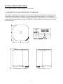
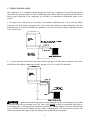
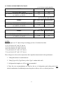
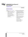
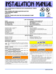
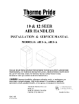
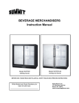
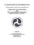
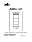
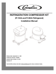
AIR CONDITIONING
14 SEER
INSTALLATION & SERVICE MANUAL
Thermo Products, LLC.
North Judson, Indiana
• • IMPORTANT • •
Do Not Destroy:
This envelope contains your assembly instructions and guarantee.
This device is potentially dangerous if improperly installed.
We recommend installation by qualified heating & air conditioning contractors.
Please read the enclosed instructions carefully, before & during installation.
Please keep these instructions as permanent reference near appliance.
MAC-200
ECN 5003-MA
CONTENTS
SECTION
PAGE
INSTALLATION INSTRUCTIONS
3
A. DESCRIPTION OF AIR CONDITIONING CONDENSER
3
B. LOCATION OF OUTDOOR CONDENSING UNIT
4
C. TUBING INSTALLATION
5
D. TUBING SIZE REFERENCE CHART
6
E. INSTALLATION OF TUBING LINES TO SERVICE VALVES
7
F. DUCT SYSTEM
8
G. ELECTRICAL
9
INITIAL START-UP OF OUTDOOR CONDENSING UNIT
AND HOW TO MEASURE SUPERHEAT
13
RECOMMENDATIONS FOR OPERATING AT LOWER
OUTDOOR AMBIENT CONDITIONS.
14
USER INFORMATION
14
SPECIFICATIONS
15
REPLACEMENT PARTS
15
2
INSTALLATION INSTRUCTIONS
NOTE: KEEP INSTRUCTIONS READILY AVAILABLE.
A. DESCRIPTION OF AIR CONDITIONING CONDENSER
The outdoor condensing unit is designed and built with a totally enclosed (hermetic) scroll compressor
which offers the advantages of simplicity, quiet operation and reduced condenser size. The entire air
conditioning system has been built and performance tested against rigid standards. The installation must
comply with the National Electrical Code ANSI/NFPA 70-(latest edition), any state or local codes, and
these instructions.
3
B. LOCATION OF OUTDOOR CONDENSING UNIT
The primary consideration in selecting the location of the outdoor-condensing unit is how the location
affects the length of the refrigerant tubing lines. Bear in mind, that the longer the tubing line, the greater the
pressures drop causing a reduction in the cooling capacity of the unit.
Another consideration in the location selection is the sun load placed on the outdoor condensing unit.
Locations, which place the unit in direct exposure to the sun during the majority of a day, should be avoided
if possible. Inside corners on the southeast or southwest corners are to be avoided as the heat build-up in
such corners would place an increased workload on the unit. Shaded locations on the north side of a home or
office are generally best if practical.
Mount the unit on a sturdy base at least one inch above the ground. Be sure to use well-tamped gravel fill
beneath the blocks or bricks to prevent settling if concrete blocks or bricks are used. Use a minimum 4"x4"
"treated" timbers plus gravel fill to prevent settling if timbers are used.
:A premature compressor failure may result and will "VOID THE WARRANTY" if the
outdoor condensing unit is located in an enclosure such as a garage or not in accordance with these
instructions.
Please refer to the Peace of Mind Warranty Certificate included with this product for warranty
information.
All models feature an “up-flow” airflow design discharged through the top grill. For this reason, the outdoor
condensing unit should not be located under an overhang or any other construction, which would direct the
discharged air back to the outdoor condensing unit. The unit should be located as illustrated below.
4
C. TUBING INSTALLATION
The compressor oil is constantly pumped through the liquid line, evaporator coil, and back through the
suction line in normal operation of an Air Conditioning system. Please follow the guide lines listed below to
insure proper lubrication of the compressor by avoiding oil accumulation at undesirable points in the
system.
1. No traps in the suction line are necessary if the outdoor condensing unit is level with the indoor
evaporator coil or the indoor evaporator coil is 4 feet or less lower than the outdoor condensing unit. Any
horizontal runs of suction line should have minimum 1/2" pitch towards the outdoor condensing unit for
every 10 feet of line.
2. A trap is necessary in the suction line at the indoor evaporator coil if the indoor evaporator coil is more
than 4' below the outdoor condensing unit and 1 trap per every 10’ of vertical rise thereafter.
: A gradual loop in the tubing can be constructed to take up the excess tubing if you find that
too much tubing has been brought onto a job. Such a loop MUST be kept in a horizontal (flat) plane to
avoid trapping the oil. Refrigerant lines should be inserted into a suitable conduit or raceway when the lines
are to be buried between the building and the outdoor condensing unit. The lines must be provided with
sufficient protection and support to prevent damage when installed above the ground.
5
D. TUBING SIZE REFERENCE CHART
0’-50’ TOTAL LINE LENGTH
SUCTION LINE LIQUID LINE
MODEL
AC14241E2 &AC14301E2
AC14361E2, AC14421E2, AC14481E2 &AC14601E2
AC14483E2, AC14603E2
3/4”
3/8”
7/8”
1/2”
50’-75’ TOTAL LINE LENGTH
SUCTION LINE LIQUID LINE
MODEL
AC14241E2 &AC14301E2
AC14361E2, AC14421E2, AC14481E2 &AC14601E2
AC14483E2, AC14603E2
7/8”
3/8”
1-1/8”
1/2”
75’-100’ TOTAL LINE LENGTH
SUCTION LINE LIQUID LINE
MODEL
AC14241E2, AC14301E2 &AC14361E2
AC14421E2, AC14481E2 &AC14601E2
AC14483E2, AC14603E2
1-1/8”
1/2”
1-1/8”
5/8”
NOTES:
For line lengths over 25’ adjust charge accordingly per foot of variation from chart.
.
.65 oz. per foot for 3/8” and 3/4” line set
.674 oz. per foot for 3/8” and 7/8” line set
.694 oz. per foot for 1/2” and 7/8” line set
.72 oz. per foot for 1/2” and 1-1/8” line set
.76 oz. per foot for 5/8” and 1-1/8” line set
These charges are to be used in conjunction with a superheat measurement for best performance.
1. Tubing dimensions are outside diameter.
2. Tubing Type ACR, (Type K heavy wall or Type L medium thick wall)
3. Refrigerant line lengths over 100’ are not recommended.
4. These line size recommendations are based on the use of refrigeration grade tubing and do not
include considerations for additional pressure drops due to elbows, valves, or reduced joint sizes.
6
E. INSTALLATION OF TUBING LINES TO SERVICE VALVES
Please read the following instructions carefully before connecting your line set to the service valves.
** EXTREME CAUTION SHOULD BE USED WHEN BRAZING JOINTS. KEEP TORCH
AWAY FROM CONDENSER CABINET, ALUMINUM COIL AND PLASTIC MESH WRAP.
1. Wrap a wet rag around the valve body and copper stub before
brazing. Flux the copper tube and the stub. Braze the joint, then
use a second wet rag to cool joint before removing first rag
wrapped around service valve.
When making “on the job” tubing, a solder such as SilFos®, PhosCopper®, Easy-Flo® 35 or 45, should be used. No attempt will be
made here to instruct proper soldering or brazing technique but it
is necessary for the installer to use an accepted technique in
accordance with good existing practices.
2. All joints and fittings must be properly leak tested as per EPA
guidelines after “on the job” tubing has been made up. The line
set and the evaporator coil must be evacuated to 29.96” Hg (1000
microns) or lower when all joints and fittings are leak free. The
service valves on the condenser may then be opened to release the
refrigerant to the system. Verify proper system performance. See
condensing unit manual for additional performance data.
3. This is not a back seating valve. Open the valve cap with an
adjustable wrench. Insert a 3/16” or 5/16” hex wrench into the
stem. Back-out counterclockwise until the valve stem just touches
the retaining ring. This opens the valve completely. The gauge
port is (open) accessible at all times.
NOTE: Make sure all connections have been leak checked before
opening service valves.
4. Replace the valve cap “finger-tight” then tighten an
additional 1/12 turn or 1/2 hex flat. A metal-to-metal seal
is now complete.
IF THE VALVE STEM IS BACKED OUT PAST THE RETAINING RING, SYSTEM PRESSURE
COULD FORCE THE VALVE STEM OUT OF VALVE BODY AND POSSIBLY CAUSE PERSONAL
INJURY. IN THE EVENT THE RETAINING RING IS MISSING. DO NOT ATTEMPT TO OPEN
VALVE.
7
F. DUCT SYSTEM
The duct system and load sizing calculation should follow the design standards of Air Conditioning
Contractors of America (ACCA) - Manuals D&J -or the American Society of Heating, Refrigeration & Air
Conditioning Engineers, Inc. (ASHRAE) Fundamentals Volume (latest edition).
To quickly aid you in evaluating existing duct systems, review the chart below. The chart shows the CFM
capacity for square inch areas based on .10" W.C. static pressure (SP) loss on the supply systems.
To insure the necessary air handling capacity of a duct system, each of the system's components (trunk lines,
takeoff's, runs and register and grill free areas) must be properly sized and matched together. A 12x8 duct
with a 400 CFM capacity, for example, WILL NOT flow 400 CFM if the register(s) can only flow a total of
200 CFM.
When sizing the return air duct system, the air handling capacity MUST BE EQUAL TO the supply system
at a minimum. It is recommended that you follow design parameters established by ACCA or ASHRAE on
the return air duct systems.
8
G. ELECTRICAL
All wiring must conform to the provisions of local codes or, in the absence of local codes, with the
provisions of the National Electrical Code, "Latest Edition" and this instruction manual. An equivalent type
wire must be used if any of the original wire supplied with the unit needs to be replaced.
All field wiring of hazardous voltages must be routed through conduit to the 7/8” access hole provided in
the base of the Control Panel.
Reference Table A for unit electrical characteristics. Bring proper service to the unit through a circuit
breaker or fused disconnect switch, in accordance with local codes. In the case of a single phase 230 VAC
unit, the neutral wire should be brought to the unit in order to provide ground service. A ground wire must
be connected to the unit at the screw or pressure connector marked "ground".
The best fuse size is the smallest fuse that will allow the equipment to operate continuously without any
nuisance trips. This type of fuse will give the equipment maximum protection. A time delay type fuse; such
as Fustat® or Fusetron®, will prevent nuisance trips due to the starting current (locked rotor amps, LRA).
9
FUSE SIZING - TABLE A
Recommendations
Fuse or HACR
Min.
Minimum
Fan
Circuit
Copper Circuit Breaker
Motor Ampacity Wire Size* Min. Max. 2
Voltage/
3
4
FLA5
(AWG)
Unit Model Phase/ Hertz RLA
AMPS
LRA
AMPS AMPS
58.3
0.8
18
#12
20
25
AC14241E2 208-230/1/60 13.5
64
0.8
17
#12
20
25
AC14301E2 208-230/1/60 12.8
77
0.8
19
#12
20
25
AC14361E2 208-230/1/60 14.1
112
0.8
24
#10
25
30
AC14421E2 208-230/1/60 17.9
109
1.6
26
#10
30
35
AC14481E2 208-230/1/60 19.9
134
2.1
36
#8
35
40
AC14601E2 208-230/1/60 26.4
83.1
1.6
18
#12
20
25
AC14483E2 208-230/3/60 13.1
16
110
2.1
23
#10
25
30
AC14603E2 208-230/3/60
NOTE: Recommended wire sizes are for copper conductors only.
*Use (as minimum) type "T" or "TW" wire. 60 C.
Compressor
Local and/or national electrical codes dictate which wire size you must use!
For example:
1
If a 25 or 30 amp fuse is used, a minimum wire size of 10 AWG must accompany it.
2
If you fuse to maximum sizes, your wire size must be adjusted accordingly.
3
R.L.A.=Compressor running load amps.
4
L.R.A.=Compressor locked rotor amps.
5
F.L.A.=Full load amps of condenser blower motors.
In the event a fuse blows, investigate for the cause. Do not put in a larger fuse and do not exceed maximum
fuse size listed on name plate. The name plate is located just above the valve connection on the outside
surface of the outdoor unit.
NOTICE: Before the Air Conditioner unit is started, the following points must be checked by the installer
and/or electrician.
1). Check every electrical connection of "PUSH-ON" or "SCREW-ON" type terminals to insure it is secured
tightly on its proper post.
2). Review wiring diagram for proper routing.
3). All wiring must comply with NEC or local codes for wire sizes. Also, it is suggested that the next larger
size wire to be used when long runs in excess of 100 ft. are experienced. Reference the following wiring
diagrams when wiring or servicing.
A loose terminal will cause poor flow of electrical power to the compressor and result in very high current
draw. This can lead to blown fuses, burned wires, burned contact points and a premature compressor failure.
Each electrical contact has been factory checked, however, connections may loosen up due to vibration in
transit. Please be certain that all electrical connections are tight.
10
UNIT WIRING DIAGRAMS
SINGLE PHASE
THREE PHASE
χ WARNING: CORRECT POLARITY REQUIRED.
IF UNIT FAILS TO START PROPERLY, SWAP POWER WIRES.
SPECIFICATIONS
INPUTS
R, R-C, C
Y, R
LPC1, LPC2
HPC, HPC
Secondary of control transformer ~ 18-30 VAC
From Thermostat
Low Pressure Switch
High Pressure Switch
OUTPUTS
CC
ALR
Compressor Contactor ~ 1.5 Amp
Alarm Output (Switched R) ~ 2 Amp
TOLERANCE
RANDOM START
150-180 seconds*
DELAY ON BREAK
fixed 180 seconds*
TEST MODE
DOB = 10 seconds, RNDM STRT = 3 seconds*
*All timings +/- 10%
11
PRINTED CIRCUIT BOARD
MODE OF OPERATION
STATUS LED A green status LED indicates that control power is present.
A red status LED indicates DELAY ON BREAK or faults. A flashing red LED indicates:
NO FLASH
COMPRESSOR IS RUNNING
1 Flash
2 Flash
3 Flash
4 Flash
5 Flash
6 Flash
DELAY ON BREAK
Less-than 1 Hr since loss of LPS
Less-than 1 Hr since loss of HPS
Less-than 1 Hr since loss of LPS & HPS
Manual lockout LPS
Manual lockout HPS
RANDOM START When power is first applied to the PCB, a random start time delay will occur that is
150-180 seconds long. If the thermostat is calling (Y) and the high-pressure switch is closed, the
compressor contactor will energize after the random start time is complete.
DELAY ON BREAK Breaking the circuit with the HPS, LPS, or the thermostat will de-energize the
compressor contactor and initiate the DELAY ON BREAK timer.
The compressor contactor will remain de-energized until the DELAY ON BREAK time has expired.
The DELAY ON BREAK time is 180 seconds.
HIGH PRESSURE SWITCH If the HPS opens while the compressor contactor is energized for greater
than 500 ms, the compressor contactor will de-energize until the DELAY ON BREAK time has expired
and the HPS has closed.
If the HPS opens twice within 1 hr, the fault protection feature will energize and the control will go into
lockout. The control will not reset until the thermostat and/or power is cycled and the HPS is closed.
LOW PRESSURE SWITCH There is a 120-second bypass time for the LPS. If the LPS opens for
greater than 120 seconds, the compressor contactor will de-energize until the DELAY ON BREAK time
has expired and the LPS has closed.
NOTE: If the LPS opens twice within 1 hr, the fault protection feature will energize and the control will
go into lockout. The control will not reset until the thermostat and/or power is cycled and the LPS is
closed.
12
INITIAL START UP OF OUTDOOR CONDENSING UNIT
On cooler days (65° F or lower), attempts to operate the air conditioner and take gauged pressure readings
may be unsuccessful, as unusually low pressures will be observed on the suction line. This type of operation
may give the impression of an undercharged unit. Such is NOT necessarily the case. The low-pressure
reading may exist because of the large condenser surface area and the cold ambient air removing so much
heat from the refrigerant. Sub-cooling occurs and results in very low pressures. Adding refrigerant in cold
weather will result in an overcharged unit, which may then trip out on high pressure limit during warm or
hot weather. Line pressures should not be taken for test purposes when the outdoor temperature is below 70°
F since a false reading may occur. Do not attempt to operate the air conditioner on a day of 45° F or cooler.
TABLE 1: APPROXIMATE OPERATING PRESSURES
Inside Temp. vs.
Outside Temp. vs. Liquid
Suction Press.
Press.
INSIDE
SUCTION
OUTSIDE
LIQUID
TEMP.
PRESS.
TEMP.
PRESS
(ºF)
(ºF)
(P.S.I.G.)
(P.S.I.G.)
65
106
70
266
70
117
75
286
72
121
80
308
74
126
85
331
76
131
90
354
80
140
95
380
85
154
100
406
90
168
105
434
When an inside temp. of 76– 78ºF is reached then
superheat measurement must be between 8 –
10ºF. This is done by comparing the gauge temp.
of R-410A on the suction line to the measured
temp. on the low side of the condenser. The
difference is the superheat. If the superheat is less
that 8 ºF decrease charge. If the superheat
is more than 10ºF then increase charge.
Another check on system charge, would be to
measure the temperature of the liquid line leaving
the condenser and it’s R-410A gauge temperature.
For proper operation, the measured liquid temperature will be about 10ºF lower than its gauge temperature.
If the difference is less add charge. If the difference is greater remove charge. The system should run for
at least 10 minutes before rechecking.
All Thermo Pride outdoor condensing units are equipped with gauge ports to connect both liquid and
suction line pressure gauges. Refrigerant hoses must be the type which incorporate a "finger" to depress the
core. Connections may be made to ports at any time; even while unit is in operation. Follow EPA guidelines
in connecting service equipment to refrigerant lines. For example: The use of quick connects and short
service hoses are recommended to minimize refrigerant losses.
: Refrigerant is under pressure. Guard against refrigerant spraying into the face or
on skin. Always wear protective equipment, i.e. safety glasses or goggles and gloves when working
with refrigerant.
: R-410a systems operate at higher pressures than R-22 systems. Do not use R-22
service equipment or components on R-410a equipment. Service equipment must be rated for R410a.
Line pressures on an operating air conditioning unit will vary with outdoor temperatures. As outdoor
temperatures rise, pressures will also rise. See pressure temperature chart for system line pressures at
different temperatures.
The suction pressure is the most significant when reading gauges. If a unit is suspected of low charge, unit
should be recharged using the suction pressure as a guide. Unit is fully charged when proper suction
pressure is obtained. Any additional refrigerant may cause damage or additional problems.
13
The pressure/temperature chart on the wiring diagram is to serve only as a guide. Pressures shown are
realistic averages, which will vary somewhat with changes in air temperatures, air volume across the
evaporator coil, condenser coil, and changes in humidity - both inside and outside, and variations in line
length.
: DO NOT UNDER ANY CIRCUMSTANCES; HEAT THE REFRIGERANT CYLINDER
WITH A TORCH OR BY ANY OTHER MEANS OTHER THAN WARM WATER. EXCESSIVE
PRESSURES GENERATED IN THIS MANNER MAY WEAKEN THE REFRIGERANT CONTAINER
AND RESULT IN A CYLINDER EXPLOSION!
If a charge must be added to the system, 410A refrigerant must be removed from the storage cylinder as a
liquid. Slowly add liquid refrigerant through the suction service port while the compressor is running.
RECOMMENDATIONS FOR OPERATING AT LOWER OUTDOOR AMBIENT CONDITIONS
If you are going to be operating the system below 65°F, Thermo Products specifies you must add to the
system the items listed below to aid in its longevity and durability of the compressor.
1.
2.
3.
4.
There should be a crankcase heater installed on compressor.
A low ambient control (45° contact) added to the 24 volt control circuit.
Suction line accumulator.
Confirm compressor superheat.
These items will assist in preventing liquid floodback, flooded starts, and refrigerant migration during off
cycle. These situations are detrimental to the life of a compressor.
USER INFORMATION
The following maintenance points should be reviewed periodically to assure that the air conditioning
system will operate properly.
1.) Keep clean air filters in the path of the air flow. If excessively dirty air filters are not changed, this
will cause poor performance of the system, put unnecessary strain on the compressor and this may
cause the system to lock out. Never operate system without clean air filters in place.
2.) Keep the outside condenser coil clean by spraying with a garden hose from the inside of the coil
outward.
WARNING: TURN OFF OR DISCONNECT THE ELECTRICAL
POWER SOURCE BEFORE CLEANING THE CONDENSER COIL.
If the air conditioning system will not operate, check the following points before calling a qualified
serviceman.
1.) Is the sub-base of the thermostat switched to the “COOL” position?
2.) Is the temperature setting on the thermostat low enough to bring the air conditioner on?
3.) If the fan motor or compressor have locked out on thermal-overload, it may be necessary to wait
several hours before the unit will restart. If this happens with any regularity, call your local
serviceman.
14
SPECIFICATIONS
AC14481E2 & AC14601E2 &
3E2
3E2
Unit Model
AC14241E2
AC14301E2
AC14361E2
AC14421E2
Capacity
BTU/H*
24,000
29,200
35,000
39,500
45,000
58,500
Evaporator
CFM
800
1,000
1,200
1,400
1,600
1,800
R410A oz.*
92
92
92
108
108
108
Shipping
Weight
185
185
189
211
212/207
215/212
*May vary with, dependant on evaporator selection. See full A/C spec page. (Approximate charge, see unit
rating label for factory charge) Contact Thermo Pride technical service @ (574) 896-2133 for more info
REPLACEMENT PARTS
15
16