1
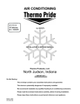
ACCESSORY KIT INSTALLATION MANUAL
THERMAL EXPANSION VALVE KITS
R-22 – S1-1TVM2**, 1TVM7** & R-410A – S1-1TVM4**, S1-1TVM9**
FOR MODELS:
COILS - FC, MC, PC, UC, HD, HC, G4FA, G4FD & AIR HANDLERS - AH, AV, & F*FP
GENERAL INFORMATION
5.
This thermal expansion valve (with internal check valve) is to be
used with flex coils for models listed above. This kit is required
to provide overall rated system performance improvement. The
kit can be applied to the listed indoor coils and air handlers,
both for heat pump and cooling applications.
The kit consists of a bolt-on thermal expansion valve, 2.5 feet of
thermal insulation, bulb straps or bulb clamp and this instruction.
6.
Install the liquid line to the top of the thermal expansion
valve with fitting supplied with the liquid line. Hand modify
the liquid line to align with casing opening. Hand tighten
the liquid line and an additional 1/4 turn to seal.
Install the TXV equalizer line into the vapor line as follows:
a.
7.
When a TXV kit is installed, a hard start kit may be required.
Consult your product data sheet.
Refer to Tabular Data sheet for specific model TXV/match-up.
Install the TXV bulb to the vapor line near the equalizer
line, using the bulb clamp(s) furnished with the TXV
assembly. Ensure the bulb is making maximum contact.
See Figure 2 for proper bulb location. See Figure 3 for
clamp assembly on 1TVM valve.
a.
• 1TVM2, 1TVM7 series TXV kits are R-22 AC and HP.
• 1TVM4, 1TVM9 series TXV kits are for R-410A AC and HP.
INSTALLATION
b.
To install the thermal expansion valve, use the following steps.
The coil will have to be pulled out of the casing for easy access.
1.
Relieve the holding charge by pulling off the rubber cap
plug on the suction manifold line of the coil.
c.
ID coil is under 30 psig pressure.
2.
After holding charge is completely discharged, loosen and
remove the schraeder cap seal.
3.
Loosen and remove distributor cap seal.
4.
Install the thermal expansion valve to the orifice distributor
assembly with supplied fittings. Orient the TXV as shown in
Figure 1. Hand tighten and turn an additional
1/4 turn to seal. Do not overtighten fittings.
VAPOR
LINE
THERMAL
EXPANSION
VALVE BULB
(Cover completely
with insulation
provided)
LIQUID
LINE
THERMAL
EXPANSION
VALVE
TXV
EQUALIZER
LINE
DISTRIBUTOR
BODY
FIGURE 1: Kit Installation in System
Johnson Controls Unitary Products
Hand tighten the 1/4” SAE nut to the schraeder fitting
and an additional 1/3 turn to seal.
Bulb should be installed on a horizontal run of the
vapor line if possible. The bulb should be installed on
top of the line.
If bulb installation is made on a vertical run, the bulb
should be located at least 16 inches from any bend,
and on the tubing sides opposite the plane of the
bend. The bulb should be positioned with the bulb tail
at the top, so that the bulb acts as a reservoir.
Bulb should be insulated using thermal insulation provided to protect it from the effect of the surrounding
ambient temperature. Cover completely to insulate
from air-stream.
8.
Slide the coil in the cabinet and install the tubing connect
plate. Soak the heat shield in water and slide it in place
using the suction and liquid line holes provided.
9.
Align the suction and liquid line sets to the suction and liquid tubing and wrap the liquid and suction tubing with wet
rag before brazing.
Dry nitrogen should always be supplied through the
tubing while it is being brazed, because the temperature is high enough to cause oxidation of the copper
unless an inert atmosphere is provided. The flow of
dry nitrogen should continue until the joint has cooled.
Always use a pressure regulator and safety valve to
insure that only low pressure dry nitrogen is introduced
into the tubing. Only a small flow is necessary to displace air and prevent oxidation.
All connections to be brazed are copper-to-copper and should
be brazed with a phosphorous-copper alloy material such as
Silfos-5 or equivalent. DO NOT use soft solder.
Nitrogen can be introduced through the Schraeder access
(located at the OD unit connection of the refrigerant line). The
Schraeder core can be removed before connecting the source
of nitrogen, but should be reinstalled prior to the evacuation and
charging of the refrigerant lines and ID coil.
166806-UAI-H-0408
10. Braze the line set to the units
11. Leak check refrigerant lines and indoor coil connections. If
leak free, remove leak check charge, reinstall any
Schraeder cores that were removed from the outdoor unit
and evacuate refrigerant lines and ID coil. Evacuate
through the Schraeder access valves of the liquid and
vapor service valves on OD unit.
*
TAIL
END
UP
ROTATE BULB TO KEEP
TAIL AT BOTTOM
12. After the interconnecting refrigerant lines, TXV assembly
and ID coil have been evacuated, the liquid and vapor line
valves at the OD unit can be opened to release the refrigerant charge into the complete system. The proper procedure for opening these valves is covered in the OD unit
installation instructions.
13. The OD unit factory refrigerant charge includes the charge
for 15 feet of interconnecting vapor and liquid lines. If interconnecting lines are longer than 15 feet, additional charge
must be added for the length. You may refer to “Refrigerant
Piping Guide” for line sets over 25 ft. The OD unit installation instructions list the charge required per foot of liquid/
vapor lines. Also, some indoor coil matches may require
additional charge. This charge is also listed in the OD unit
installation instruction. The additional charge should be
introduced into the system by means of a calibrated charging cylinder or other means of accurately weighing the
refrigerant.
VERTICAL
RISER
MAX. 3 FT-LB (4 Nm)
TORX 25 WITH SLOT
FIGURE 2: Correct Bulb Locations
2
SCREW
TXV BULB
1
NUT
CLAMP
SUCTION
LINE
FIGURE 4: Clamp Attachment for 1TVM (Option 2)
FIGURE 3: Clamp Attachment for 1TVM (Option 1)
Subject to change without notice. Printed in U.S.A.
Copyright © 2008 by Johnson Controls, Inc. All rights reserved.
Johnson Controls Unitary Products
5005 York Drive
Norman, OK 7306
166806-UAI-H-0408
Supersedes: 166806-UAI-G-0108