1
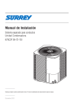
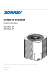
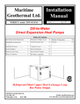
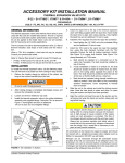
A Div of ITW FEG, LLC.
INSTRUCTION MANUAL
KRES
Equipment Stands
Self-Contained and Remote
Kairak
500 S. State College Blvd.
Fullerton, CA 92831
IM-ES-REV 5-09-06
PN 4406010-1
KAIRAK
Page 2
GENERAL
Kairak KRES model refrigerated equipment stand units are available in many lengths from 36 to
120 inches long. These units are available as a refrigerated or freezer storage compartment.
The condensing systems are designed to be installed with minimal clearance to walls or other
equipment.
These models are available as self-contained or remote. Standard features on these models
include electronic temperature control, all stainless steel construction (galvanized back), 4-inch
casters for self-contained models and 6-inch legs for remote models, double or single wide
drawers and exterior dial thermometer. Available options include, marine or flat top, stainless
steel back, 6-inch casters and drawer locks. Some options are not available on all models.
INSTALLATION
Prior to installation, test the electrical service to assure that it agrees with the specifications of
the equipment marked on the data plate. The data plate is located inside the storage cabinet.
(See Fig. 1)
Serial No.
Electrical &
Refrigeration
Specifications
SAMPLE
Fig. 1
UNPACKING
Inspect equipment for shipping damage prior to installation. If shipping damage is found, save
the packing materials and contact the carrier within 15 days of delivery. Some components are
packed and shipped inside the storage cabinet to avoid damage during shipment. Remove
these items from the cabinet and remove packing materials. See “Installing Parts Shipped
Loose” for installation instructions. Cut the plastic ties holding the shelves in place.
- 2-
IM-ES-REV 5-09-06.doc5-09-06
KAIRAK
Page 3
LOCATING THE EQUIPMENT
All model lengths can be installed with minimal clearance at the back and sides of the units
INSTALLING PARTS SHIPPED LOOSE
COMPRESSOR FILTER
Remove louvered panel by lifting up and pulling out entire panel. Slide the filter into the tracks
located below the compressor compartment. Be careful not to catch the filter on sharp edges
when installing. Replace louvered panel by installing top of panel into track and pushing in the
bottom so that the locking clips fit inside the opening. (See Fig. 2).
Installing Filter
Replacing louvered panel
Fig. 2
- 3-
IM-ES-REV 5-09-06.doc5-09-06
KAIRAK
Page 4
ELECTRIC CONDENSATE EVAPORATOR
Some units may come with the electric condensate evaporator shipped loose. To install, attach
the two (2) mounting rails to the bottom of the cabinet with 4 or 6 (depending on the model) #632 x 3/8 phillips head screws. Place the condensate evaporator in the heater bracket. Slide the
heater bracket into the mounting rails. Plug the electrical cord into the heater and the electrical
outlet. NOTE: Drain should be located above the condensate evaporator opening. (See Fig. 3)
Installing Electric Condensate Evaporator
Fig. 3
- 4-
IM-ES-REV 5-09-06.doc5-09-06
KAIRAK
Page 5
REFRIGERATION LINES (Remote Units)
WARNING: REFRIGERATION LINES ARE SHIPPED UNDER PRESSURE. USE CAUTION
WHEN OPENING LINES.
On remote units, refrigeration lines for suction and supply are located on the back of the unit
near the bottom. The suction line is marked “Suction” and is 3/8” copper tubing. The supply line
is 1/4” copper. See “Electrical Connections” section for wiring instructions.
If no holding charge is evident upon opening lines, contact Kairak Service and Parts Department
at 714-870-8661 immediately.
Cut refrigeration tubing with tube cutter (not a hacksaw) and deburr end of tube. Degrease
tubing prior to field connection. Use Silfos 5% for refrigerant line brazing. 50/50 or cold solder
is not acceptable.
For system charge, follow remote refrigeration system manufacturer’s instructions.
ELECTRICAL CONNECTIONS
Refer to the wiring diagram shipped with the unit located inside the compressor compartment or
on the back of the unit.
CORD CONNECTED UNITS (Self-Contained models)
Plug the unit into a properly sized outlet. See data plate located inside storage cabinet for
circuit sizing.
WARNING: THIS MACHINE IS PROVIDED WITH A THREE-PRONGED GROUNDING PLUG.
THE OUTLET TO WHICH THIS PLUG IS CONNECTED MUST BE PROPERLY GROUNDED.
IF THE RECEPTACLE IS NOT THE PROPER GROUNDING TYPE, CONTACT AN
ELECTRICIAN.
PERMANENTLY WIRED UNITS (Remote models)
A junction box located on back of the machine near bottom is provided for electrical field
connections. See wiring diagram shipped with unit on the back of the unit for electrical ratings.
- 5-
IM-ES-REV 5-09-06.doc5-09-06
KAIRAK
Page 6
PRESTART CHECKS
DEFROST TIME CLOCK SETTINGS
All models have a defrost time clock that is set to defrost 3 times a day for a 15 minute time
period. The defrost settings are factory set at 12:00 a.m. to 1:00 a.m., 2:00 a.m. to 2:30 a.m.
and 5:00 a.m. to 6:00 a.m. To change this setting, set the pins to desired off times. Each pin
represents 15 minutes. Pins pulled out away from center of time clock represent refrigeration
off. Pins pushed toward center indicate refrigeration on. Make sure time clock is set to the
correct time of day.
To set the time of day, rotate the disc in the direction of the arrows (clockwise rotation) to align
the hands to the correct time of day. (See Fig. 4)
ON cycle
Pins in
Timer shown with clock
set at 8 a.m.
OFF cycle
Pins out
OFF cycle
Pins out
Fig. 4
- 6-
IM-ES-REV 5-09-06.doc5-09-06
KAIRAK
Page 7
TEMPERATURE CONTROL SETTINGS
All temperature settings are preset at the factory but local conditions may necessitate slight
adjustments.
On self-contained refrigerated models the temperature control (shown in Fig. 5) is located in the
compressor compartment.
Base Temperature
Control
Power Switch
KRES Self-contained
Fig. 5
- 7-
IM-ES-REV 5-09-06.doc5-09-06
KAIRAK
Page 8
On remote models, the controls can either be inside the control cabinet similar to that shown in
Fig. 5 or inside the refrigerated base as shown in Fig. 6.
Base
Temperature
Control
KRES Remote
Fig. 6
On both self-contained and remote refrigerated units, the temperature control should be set at
37°F with a 3°F differential. This display should read between 34°F and 40°F. The temperature
control setting is “locked” to avoid unauthorized adjustments. Therefore, adjustments to the set
point must be made by an authorized service technician.
On freezer base units, the temperature control should be set at 0°F with 2°F differential.
Temperature display should read between –2°F and 2°F.
- 8-
IM-ES-REV 5-09-06.doc5-09-06
KAIRAK
Page 9
OPERATION
A thermometer is provided on all refrigerator and freezer cabinets.
Allow cabinet to reach normal operating temperature before loading (approximately 1 hour).
The refrigerated storage cabinet is designed to maintain temperatures between 33°F and 40°F,
or –2°F to 2°F for a freezer storage cabinet. If the base is overloaded with warm food products,
a certain amount of time is required to remove heat from items before operating temperatures
can be maintained. The system is designed for storage of refrigerated or frozen product.
Frequently opening the drawers will increase the temperature in the cabinet and will require a
certain amount of time to recover.
SHUTDOWN FOR EXTENDED PERIODS
If the units are not to be used for an extended period of time, disconnect the electrical power
supply and the drawers to the storage cabinet. As soon as the cabinet has warmed to room
temperature, wipe out the base interior.
MAINTENANCE PROCEDURES
CLEANING
WARNING: DISCONNECT ELECTRICAL POWER SUPPLY BEFORE CLEANING ANY
PARTS ON THE UNIT.
STORAGE CABINET
Use warm, soapy water to clean storage cabinet and doors. NEVER use cleaners containing
grit, abrasive materials, bleach or harsh chemicals. Rinse thoroughly and dry with a clean soft
cloth. Always rub in the same direction as the grain pattern on the stainless steel.
Remove the drawers from the drawer frame module. The drawer frame module can be removed
by loosening the black clamping knob on the Cross Rail Locks and Liner Locks. Pull the Cross
Rail Locks toward the center of the drawer frame module and allow the Liner Locks to drop
away from the top of the liner. The entire frame assembly is now free to slide out of cabinet.
(See Figs. 7 & 8).
- 9-
IM-ES-REV 5-09-06.doc5-09-06
KAIRAK
Page 10
Liner Lock
Black
Clamping
Knob
Cross Rail Lock
(1 on each side
of drawer)
Fig. 7
Drawer Module
Cross Rail
Lock
Black
Clamping
Knob
Fig. 8
- 10 -
IM-ES-REV 5-09-06.doc5-09-06
KAIRAK
Page 11
CONDENSING UNIT
WARNING: DISCONNECT ELECTRICAL POWER SUPPLY BEFORE CLEANING ANY
PARTS ON THE UNIT.
The condensing unit coil and filter must be cleaned regularly on self-contained models for
optimal performance. The operating environment will affect the required frequency of cleaning.
However, both should be cleaned a minimum of once every three months. Air must be able to
freely circulate through the condenser. Unit performance and operating efficiency are
significantly affected by the amount of air passing through the condenser. Condenser fins that
are clogged with dirt and debris greatly reduce required airflow. Failure to keep the coil fins
and the air filter clean may cause premature compressor failure, which will not be
covered by warranty. (On models that contain filters, operating unit without filter will
void warranty).
The condensing unit is located behind the louvered panel in the compressor compartment.
Remove louvered panel by pulling on the bottom then lifting up and out. Remove rear access
panel located in the back of unit. A phillips head screwdriver is required to remove rear access
panel. Carefully clean dirt and lint from the condenser coil using a vacuum cleaner or soft
brush; do not use a wire brush.
The filter is located behind the louvered panel, below the condensing unit in the compressor
compartment. Remove filter by carefully sliding out of the tracks. Carefully clean with vacuum
or rinse with hot water exercising care not to bend or damage filter frame. Replace filter by
carefully sliding it into the tracks. Replace louvered panel by installing top of panel into track and
pushing in the bottom so that the locking clips fit inside the opening.
Replace rear access
panel. Reconnect electrical supply.
Replacement filters are available through Kairak Parts and Service Department at
714-870-8661.
EVAPORATOR COILS
WARNING: DISCONNECT ELECTRICAL POWER SUPPLY BEFORE CLEANING ANY
PARTS ON THE UNIT.
Evaporator coils should be cleaned every six (6) months for optimal performance.
The evaporator coils are located in the storage cabinet behind the coil can cover. With a phillips
head screwdriver, remove four screws and take off cover. Clean evaporator coils with a
vacuum cleaner or soft brush, do not use a wire brush. Replace coil can cover. Reconnect
electrical supply.
- 11 -
IM-ES-REV 5-09-06.doc5-09-06
KAIRAK
Page 12
TROUBLESHOOTING
SYMPTOM
Compressor fails to operate.
Compressor operates for prolonged periods
and/or continuously.
Lower storage cabinet not holding
temperature.
POSSIBLE CAUSE
• Power failure.
• Plug loose in receptacle or unplugged.
• Blown fuse or tripped circuit breaker.
• Main power switch is Off.
• Temperature controls or time clock not set
properly.
• Door gaskets not sealing properly.
• Condensing unit filter is dirty.
• Evaporator coil is iced up or dirty.
• Prolonged and/or frequent door openings
or door(s) ajar.
• Excessive load of warm food placed into
lower storage cabinet.
• Temperature control and/or time clock not
set properly.
• Door gaskets not sealing properly.
• Inadequate air circulation due to product
loading.
• Evaporator coil iced up or dirty.
SERVICE
For additional information, contact Kairak Parts and Service Department at 800-833-1106.
- 12 -
IM-ES-REV 5-09-06.doc5-09-06
KAIRAK
Page 13
A Div of ITW FEG, LLC.
1-YEAR LABOR WARRANTY
Kairak warrants that equipment manufactured by Kairak will be free from defects in
material and workmanship for a period of 1-year beginning 30 days after ship date. All work
must be pre -approved by the factory to qualify for reimbursement under this warranty.
Unapproved labor claims will not be paid. Note: t-stat and time clock adjustments are not
covered under this warranty.
1-YEAR PARTS WARRANTY
Components such as compressors, fan motors, t-stats (ETC), time clocks, expansion valves,
etc. shall be warranted for a period of 1-year beginning 30 days after ship date. Note:
gaskets, filters, cutting boards, driers, sight glasses, and freon are not covered under this
warranty. Kairak must be informed of the component failure and given the option to ship a
replacement part or authorize purchase of the part locally by the service contractor. Parts
utilized for emergency replacement and parts purchased locally by contractor shall be
reimbursed at cost, an invoice of the purchased part must be supplied with the labor invoice.
All defective parts must be returned to Kairak C.O.D. via UPS or common carrier.
5-YEAR COMPRESSOR WARRANTY
Compressor manufacturer warrants compressor components for a period of twelve months
from the serial number manufacture date. Replacement compressors required during this
period are to be acquired by over the counter exchange at the appropriate wholesaler. Kairak
will warrant the labor to replace the compressor for the first year only. After the expiration
of the compressor manufacturer warranty as indicated above, Kairak will warrant
compressors only for a period not to exceed 4-years from the original start-up date. Labor, tax,
shipping, and miscellaneous parts will not be included. Please contact our Warranty
Department for compressor replacement and procedures during this time.
PLEASE NOTE:
Contributing factors that impact refrigeration performance such as fixture doors and or
drawers being left open, hot products such as soup being placed inside the reach-in box,
fixture top insert pans being left out, improper equipment maintenance, debris such as plastic
wrap covering coil openings, food not being removed from drain areas, are all considered
maintenance and or improper usage will not be covered under warranty.
Kairak Warranty/Service Department – (800) 833-1106 After Hours – (714) 870-9400
500 S. State College Blvd., Fullerton, CA. 92831
(Phone: 714-870-8661 Fax: 714-870-6473)
- 13 -
IM-ES-REV 5-09-06.doc5-09-06