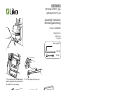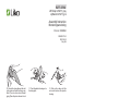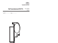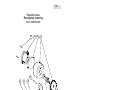
1
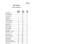
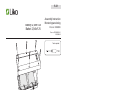
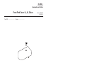
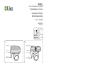
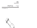
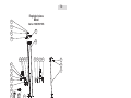
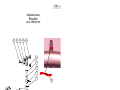
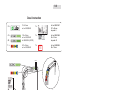
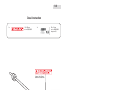
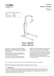
Golvo 7000 / 7007ES, facelift
Service Manual
English
3EN400401-03
2007-10-23
Prod.no: 2000009, 2000010
Proj: 675
© Copyright Liko AB
1.0
Table of Contents
Golvo 7000 / 7007ES, facelift
Position
Ref.no.
Page
Table of contents ............................................................................ 1.0 ........................ 2
Care and maintenance ................................................................... 2.0 ........................ 3
Technical Specifications ................................................................. 3.0 ........................ 4
Spare parts positions ...................................................................... 4.0 ........................ 5
Spare parts.list................................................................................ 5.0 ........................ 6
Actuator G7/G77................................................... 11 ................... 5.11 ........................ 9
Control box G7/G77 ES ........................................ 18 ................... 5.18 ...................... 11
Attachment for control box ................................... 19 ................... 5.19 ...................... 13
Hand Control ES 6-button .................................... 20 ................... 5.20 ...................... 15
Battery 2,9Ah/12V ................................................ 21 ................... 5.21 ...................... 17
Cable for charging EU ........................................ 22 ................... 5.22 ...................... 19
Cable for charging UK .......................................... 23 ................... 5.23 ...................... 20
Cable for charging US ......................................... 24 ................... 5.24 ...................... 21
Gear rack set G7/G77 .......................................... 33 ................... 5.33 ...................... 22
Spring magazine .................................................. 36 ................... 5.36 ...................... 24
Extra Battery box, incl. Batteries ........................ 139 ................. 5.139 ...................... 26
Front Cover LL, Vi, Golvo ................................... 159 ................. 5.159 ...................... 28
Extension Cable ................................................. 160 ................. 5.160 ...................... 30
Cable for charging AU/NZ................................... 248 ................. 5.248 ...................... 32
Reinforcment Plate G7/G77 ............................... 250 ................. 5.250 ...................... 33
Limit Switch G7/G77 ........................................... 251 ................. 5.251 ...................... 35
Extension Cable US ........................................... 263 ................. 5.263 ...................... 37
Safety Latch Universal Slingbar ......................... 264 ................. 5.264 ...................... 39
Motor for base width adj. G7/G77 grey............... 274 ................. 5.274 ...................... 41
Plastic housing grey ........................................... 275 ................. 5.275 ...................... 43
Lift strap G7, grey ............................................... 277 ................. 5.277 ...................... 45
Lift strap G77, grey ............................................. 278 ................. 5.278 ...................... 46
Roll frame attachment G7/77, grey..................... 279 ................. 5.279 ...................... 49
Base Motor Cover, grey ...................................... 280 ................. 5.280 ...................... 51
Front wheel 75 mm Standard ............................ 284 ................. 5.284 ...................... 53
Rear wheel 75 mm Standard .............................. 285 ................. 5.285 ...................... 55
Hook för handcontrol 2,4,6 button ...................... 292 ................. 5.292 ...................... 57
End cover handle/arm support grey .................. 293 ................. 5.293 ...................... 59
End cover arm rest, grey .................................... 294 ................. 5.294 ...................... 61
Body/Handle set for Emerg. low.device G7/G77 295 ................. 5.295 ...................... 63
Leg Protector G7, grey ....................................... 298 ................. 5.298 ...................... 65
Leg Protector G77, grey ..................................... 299 ................. 5.299 ...................... 66
Safety Latch, composite ..................................... 311 ................. 5.311 ...................... 68
Easy strapper G7................................................ 323 ................. 5.323 ...................... 70
Easy strapper G77.............................................. 324 ................. 5.324 ...................... 72
Low base kit Golvo 7007 .................................... 330 ................. 5.330 ...................... 74
Simple Troubleshooting .................................................................. 6.0 ...................... 76
Exploded views............................................................................... 7.0 ...................... 77
Components Golvo 7000 / 7007 ES ............................................... 8.0 ...................... 85
Decal instructions ........................................................................... 9.0 ...................... 90
Periodic inspection ....................................................................... 10.0 ...................... 92
Product changes........................................................................... 11.0 ...................... 96
Liko AB • Nedre vägen 100 • SE-975 92 Luleå • Sweden
tel +46 (0)920-47 47 00 • fax +46 (0)920-47 47 01
[email protected] • www.liko.com
2.0
Care and Maintenance
For safe and trouble-free operation, a few routine procedures should be performed every day the lift
is used:
•
•
•
•
•
•
•
Visually inspect the lift and check for external damage or wear
Check the slingbar connector
Check the lift strap for wear and make sure it is not twisted
Check that the safety latches work properly
Test the operation of raising and lowering and the base width function
Check that the correct lifting range has been set and that the emergency lowering functions
Charge the battery every day the lift is being used, and check the charger function
If needed, clean the patient lift with common water-based surface disinfectants. Warning! Do not
routinely use chemicals containing phenol or chlorine, since these may damage aluminium
and polyamide materials.
Transportation and storage
During transportation, or when the patient lift is not to be used for some time, the emergency button
should be pushed in. Also, when storing, keep the patient lift at a temperature exceeding freezing
point and at a relative humidity no more than 60%.
Inspection
Golvo should be thoroughly serviced at least once per year. Pay particular attention to parts that show
wear. Service must be carried out according to Liko service manual and by authorized staff.
IMPORTANT!
Repairs and maintenance may only be carried out by authorized Liko service personnel using
original Liko parts.
Service agreements
Liko invites you to sign a service agreement for regular maintenance and testing of your Golvo lift.
We always try to improve our products. Naturally, this means changes from time to time.
Please contact our local representative or your nearest Liko office to receive the latest updates.
Made in Sweden
Liko is quality certified according to ISO 9001 and environment certified according to ISO 14001.
3
www.liko.com
3.0
Technical Data
Data
Technical
Material:
Em. lowering:
Intermittent
operation:
Lifting speed: Two speeds: 4.8 cm/s (1.9 inch./s)
and 3.2 cm/s (1.3 inch./s).
Both speeds without load.
Batteries:
Two 2.9Ah - 12V valve regulated
rechargable leadacid batteries.
New batteries are provided by the
supplier.
Battery
Built-in charger for 100-240V,
charger:
50-60 Hz, max 400 mA.
Motor (mast): 24V, 6.5 A. Manufactured by Liko
with planetary gearing and safety
nut (prevents excessive wear).
Motor (base): 24V, 3.5A. Geared motor.
Wheels:
Standard front: 75 mm twin wheels.
Standard rear: 75 mm lockable
twin wheels.
Anodized aluminium.
Mechanical and electrical.
Int. Op 10/90, active operation max
2 min. Out of a time of 100, active
must be less than 10, however not
more than 2 min.
Degree of
protection:
IP 43
This device is built for indoor operation.
Type B according to the degree of protection
against electric shock.
Class ll equipment.
Patented
Measurements
Model
Max. load
L
Max
Max
A
Min
B
B1
C
D
E
F
G
H
H1
Weight Turningdiameter
Golvo 7000 ES
200
175
199
134
54
112
67-95
53-81
96
84
60
11
2,3
42
124
Golvo 7007 ES
200
185
208
144
58
119
75-102 62-90
106
94
60
11
2,3
44
133
Maximum load and weight in kg. Measurement in cm. Lifting range 126 cm, adjustable.
Model
Max. load
L
Max
Max
A
Min
B
B1
C
D
E
F
G
H
H1
Weight Turningdiameter
Golvo 7000 ES
440
69
78
53
21
44
26-38
21-32
38
33
24
4
1
93
49
Golvo 7007 ES
440
73
82
57
23
47
30-40
24-35
42
37
24
4
1
97
52
Maximum load and weight in lbs. Measurement in inches. Lifting range 49.6 inches, adjustable.
4
www.liko.com
4.0
Spare parts positions
Golvo
7000Parts
ES, 7007
ES facelift
Spare
Positions
279
250
277 278
323 324
275
36
293
264
311
295
294
21 139
11
19
33
298 299
18
274
280
251
159
159
285
284
330
160 263
22 23 24 248
20 292
5
2
www.liko.com
5.0
Spare Parts List
Spare parts
Golvo 7000 ES, 7007 ES facelift
PART.NO
POS.NO
ARTICLE
UNIT
20090014
11
Actuator G7/G77
pce
20090022
18
Controlbox G7/G77 ES
pce
20090023
19
Attachment for Controlbox
pce
20090024
20
Handcontrol ES 6-Button
pce
20090025
21
Battery 2.9 Ah/12V
pair
20090026
20090027
20090028
22
23
24
Cable for Charging EU
Cable for Charging UK
Cable for Charging US
pce
pce
pce
20090038
33
Gear Rack set G7/G77
pair
20090041
36
Spring Magazine
pce
2006106
139
Extra Battery box, incl. Batteries
pce
20390006
159
Front Fork Cover LL,Vi,Golvo
pair
X2
21090001
160
Extension Cable
pce
6
www.liko.com
5.0
Spare Parts List
Spare parts
Golvo 7000 ES, 7007 ES facelift
PART.NO
POS.NO
ARTICLE
UNIT
20090050
248
Cable for Charging AU/NZ
pce
20090051
250
Reinforcement Plate G7/G77
pce
(From serial no 7022914/7725944)
20090052
251
Limit Switch G7/G77
pce
21090011
263
Extension Cable US
pce
31590011
264
Safety Latch Universal Slingbar
pair
20090059
274
Motor Base Width Adj. G7/G77 grey
pce
20090060
275
Plastic Housing grey
pce
20090062
277
Lift Strap G7 grey
pce
20090063
278
Lift Strap G77 grey
pce
20090064
279
Roll Frame Attachment G7/G77 grey
pce
20090065
280
Base Motor Cover grey
pce
20490014
284
Front Wheel 75 mm Standard
(From serial no 7024206/7729722)
pce
pce
X2
7
www.liko.com
5.0
Spare Parts List
Spare parts
Golvo 7000 ES, 7007 ES facelift
PART.NO
POS.NO
ARTICLE
UNIT
20490015
285
Rear Wheel 75 mm Standard
(From serial no 7024206/7729722)
pce
20090058
292
Hook for Handcontrol 2,4,6
pce
20090066
293
End Cover Handle/Arm Support grey
set
X4
20090067
294
End Cover Armrest grey
pair
20090068
295
Body/Handle set for Emerg. Low. Device
G7/G77
pce
2006011G
2006012G
298
299
Leg Protector G7 grey
Leg Protector G77 grey
pair
pair
31590014
311
Safety Latch, composite
pair
20090069
20090070
323
324
Easy Strapper G7
Easy Strapper G77
set
set
20090071
330
Low base kit Golvo 7007
set
X2
8
www.liko.com
5.11
Spareparts specification
Actuator G7/G77
Prod.no: 20090014
2003-09-09
V1
7024206/7729722 Version...............................
From S/N.................................
Details included in sparepart:
Detail no.
20090014
Details:
Actuator G7/G77
Unit:
1
9
www.liko.com
5.11.1
Actuator G7-77
Ställdon G7-77
Assembly Instruction
Monteringsanvisning
Actuator G7-77
Ställdon G7-77
Prod.no: 20090014
Doc. no: 3SE630249-01
2006-03-24
17 mm
3 and 6 mm
13 and 17 mm
1. Remove the EB cover.
2. Remove the screws and the locking nut from the mast attachment.
3. Remove the mast attachment.
4. Remove the Emergency lowering
device.
5. Unfix the screw and the plastic
cover.
6. Unfix the aluminium holder
7. Unfix the spring and the slipper.
8. Push the innermast through the
mast.
9. Remove the screws from the
motorplate.
10. Remove the screws and the plastic casing. Pull out the actuator.
10
www.liko.com
5.18
Spareparts specification
Control Box G7/G77 ES
From S/N.................................
Prod.no: 20090022
2003-09-09
Version...............................
Electrical Emergency Lowering
Indication lights
LCD-display showing battery capacity
Details included in sparepart:
Detail no.
950000027
900000292
901535091
Details:
Controlbox Golvo
Plastic cover IKPT 12 15 G
Emergency guard
Unit:
1
1
1
11
www.liko.com
5.18.1
Control Box
Kontrollbox
Assembly Instruction
Monteringsanvisning
Control Box
Kontrollbox
Prod.no:
20090022, 20190013
20190014, 20290011
20290024, 20390007
20490009, 20490013
Doc. no: 3SE630223-02
2005-12-08
Tools required:
3 mm
1.
20090022 Golvo 7000/7007
20190013 Uno 100/102 EE, EM
20190014 Uno 100/102 ES
20290011 Sabina
20290024 Sabina ll
20390007 Liko Light
20490009 Viking L, Viking XL
20490013 Viking M
2.
12
www.liko.com
5.19
Spareparts specification
Attachment for Control Box
From S/N.................................
Prod.no: 20090023
Version...............................
x3
Details included in sparepart:
Detail no.
900000001
930000001
930000390
Details:
Unit:
Attachment for controlbox MBJ2 1
Screw MC6S M5x8 low
4
Screw MRT-GF M5x16
3
13
www.liko.com
5.19.1
Attachment for Control Box
Monteringsbeslag kontrollbox
Assembly Instruction
Instruction
Assembly
Monteringsanvisning
Monteringsanvisning
Prod no: 20090023
3SE630238-02
2007-09-10
Tools required:
3 mm
T25
1.
2.
3.
x1
4.
5.
x 3 (Viking M, L, XL)
x 3 (Sabina, Uno)
© Copyright Liko AB
www.liko.com
14
www.liko.com
5.20
Spareparts specification
Hand Control ES 6-button
From S/N.................................
Prod.no: 20090024
Version...............................
Details included in sparepart:
Detail no.
950000047
Details:
Handcontrol ES
Unit:
1
15
www.liko.com
5.20.1
Hand Control 2, 4, 6-button
Handkontroll 2, 4, 6-knapp
Assembly Instruction
Instruction
Assembly
Monteringsanvisning
Monteringsanvisning
Prod no: 20090024
20190016
20190017
3SE630204-07
2007-09-10
Connect cable as indicated
Connect cable 1 as indicated
Viking S
www.liko.com
16
www.liko.com
5.21
Spareparts specification
Battery 2,9 Ah/12V
From S/N.................................
Prod.no: 20090025
2003-09-09
Version...............................
Details included in sparepart:
Detail no.
950000053
Details:
Battery 1 pair with cable
Unit:
1
Two 2,9Ah - 12V valve regulated rechargable leadacid batteries.
New batteries are supplied by the manufacturer.
17
www.liko.com
5.21
Battery 2,9Ah/12V
Batteri 2,9Ah/12V
Assembly Instruction
Monteringsanvisning
Monteringsanvisning
Prod.no: 20090025
Doc. no: 3SE380201-01
2005-09-02
Tools required:
T20
Tools required:
T20
Old batteries are to be left to personnel
authoriserad by Liko, or at the nearest
station for environmental recycling.
18
www.liko.com
5.22
Spareparts specification
Cable for Charging, EU
Laddningskabel EU
Prod.no: 20090026
Doc. no: 3SE630237-01
2006-03-01
From S/N.................................
Version...............................
Tools required:
Details included in sparepart:
Details
Detail no.
Details:
Cable for charging EU
Detail no.Unit:
Unit.
9500000EU
1
19
www.liko.com
5.23
Spareparts specification
Cable for Charging, UK
Laddningskabel UK
From S/N.................................
Version...............................
Prod.no: 20090027
Doc. no: 3SE630241-01
2006-03-21
Tools required:
Details included in sparepart:
Detail no.
Details:
Details
Cable for charging UK
Unit:
Detail no. Unit.
9500000UK
1
20
www.liko.com
5.24
Spareparts specification
Monteringsanvisning
Cable for Charging, US
Laddningskabel US
Prod.no: 20090028
Doc. no: 3SE630242-01
2006-03-02
From S/N.................................
Version...............................
Tools required:
Details included in sparepart:
Detail no.
Details:
Details
Cable for charging US
Unit:
Detail no. Unit.
9500000US 1
21
www.liko.com
5.33
Spareparts specification
Gear Rack set G7-77
From S/N.................................
Prod.no: 20090038
2003-09-09
Version...............................
Details included in sparepart:
Detail no.
90181701-1
90181701-2
930000091
930000093
Details:
Gear rack
Gear rack Golvo
Locking Nut M8 Nyloc
Screw MC6S M8x22 low
Unit:
1
1
4
4
22
www.liko.com
5.33.1
Gear Rack set G7/G77
Kuggstångssats
Assembly Instruction
Monteringsanvisning
Gear Rack set G7-77
Kuggstångssats
Prod.no: 20090038
Doc. no: 3SE630213-02
2006-03-01
1.
Tools required:
13 mm
5 mm
ca 12 cm / 4,7 inch
Adjust the legs
2.
3.
E
4.
5.
Make sure that the slipper is in its place
6.
7.
A
B
D
C
Verify the stop screw is tight and the nut is in the
correct orientation. The flat of the hex must be
positioned parallel with the end of the gear rack.
C
After assembling, distance A & B must be the same.
Note 1! The cover profiles (C) must be fixed to the
middle beam (D). (Picture 6)
Note 2! Screw and nut (E) must be assembled. (picture 3)
www.liko.com
23
www.liko.com
5.36
Spareparts specification
Spring Magazine
From S/N.................................
Prod.no: 20090041
2003-09-09
Version...............................
Details included in sparepart:
Detail no.
900000106
Details:
Spring Holder KPL
Unit:
1
24
www.liko.com
5.36.1
Spring Magazine
Fjäderkassett
Assembly Instruction
Monteringsanvisning
Spring Magazine
Fjäderkassett
Prod.no: 20090041
Doc. no: 3SE630214-01
2005-10-18
Tools required:
Remove after assembly
25
www.liko.com
5.139
Spareparts specification
Extra Battery box, incl. Batteries
From S/N.................................
Prod.no: 2006106
2003-09-09
Version...............................
Details included in sparepart:
Detail no.
950000044
Details:
Battery box
Unit:
1
26
www.liko.com
5.139.1
Extra Battery Box, incl batteries
Batteribox inkl battterier
Assembly Instruction
Monteringsanvisning
Extra Battery Box, incl Batteries
Batteribox inkl batterier
Prod.no: 2006106
Doc. no: 3SE630224-01
2005-12-05
1.
2.
3.
Old batteries are to be left to
personal authorised by Liko,
or at the nearest station for
environmental recycling.
27
www.liko.com
5.159
Spareparts specification
Front Fork Cover LL, Vi, Golvo
From S/N.................................
Prod.no: 20390006
2003-10-02
Version...............................
Details included in sparepart:
Detail no.
900000419
930000424
Details:
Front fork cover
Screw M5x16N
Unit:
2
2
28
www.liko.com
5.159.1
Front Fork Cover LL,Vi, Golvo
Framhjulskåpa LL,Vi, Golvo
Assembly Instruction
Monteringsanvisning
Prod no: 20390006
3SE380202-02
2007-03-15
Tools required:
4,2 mm
M5
1.
2.
3. If not prepared with hole, drill [mm.]
4.
22,2
5
38,4
5.
6.
29
www.liko.com
5.160
Spareparts specification
Extension Cable
From S/N.................................
Prod.no: 21090001
2003-09-09
V2
Version...............................
Length 24 cm, 9,5 inche
Details included in sparepart:
Detail no.
950000058
Details:
Extension cable EU
Unit:
1
30
www.liko.com
5.160.1
Extension Cable
Skarvkabel
Extension Cable
Skarvkabel
Assembly Instruction
Monteringsanvisning
Prod.no: 21090001
Doc. no: 3SE630225-01
2005-12-22
1.
3.
2.
31
www.liko.com
5.248.1
Spareparts specification
Cable for Charging, AU/NZ
Laddningskabel AU/NZ
From S/N.................................
Version...............................
Prod.no: 20090050
Doc. no: 3SE630243-01
2006-03-21
Tools required
Details included in sparepart:
Detail no.
Details:
Details
Cable for charging, AU/NZ
Unit:
Detail no. Unit.
9500000AU
1
32
www.liko.com
5.250
Spareparts specification
Reinforcement Plate G7-77
>7022914/7725944
From S/N.................................
Prod.no: 20090051
2003-09-09
Version...............................
Details included in sparepart:
Detail no.
930000316
901211152
Details:
Screw K6S M5x10
Reinforcment Plate
Unit:
2
1
33
www.liko.com
5.250.1
Reinforcement Plate G7/G77
Bandstyrningsplåt G7/G77
Assembly Instruction
Reinforcement Plate G7-77Monteringsanvisning
Prod.no: 20090051
Bandstyrningsplåt G7-77
Doc. no: 3SE630215-01
2005-10-18
Tools required:
4,2 mm
1.
3 mm
Remove the Roll frame attachment.
Assemble the Reinforcement Plate as shown in Figure 2.
Drill two holes Ø 4.5 mm in the housing using the holes in the
Reinforcement Plate as guides.
Secure the Reinforcement Plate with the two screws.
Demontera rulländsfäste.
Montera bandstyrnings plåten enligt bild 2.
Borra två hål Ø 4.5 mm i rulländsfäste använd bandstyrnings plåten som mall.
Montera bandstyrnings plåten med skruvarna som medföljer.
Assemble strap joint/ Montera bandblecket
2.
3.
4.
5.
6.
7.
34
www.liko.com
5.251
Spareparts specification
Limit switch G7-77
From S/N.................................
Prod.no: 20090052
2003-02-05
Version...............................
Details included in sparepart:
Detail no.
Details:
Unit:
35
www.liko.com
5.251.1
Limit switch G7/G77
Ändlägesbrytare G7/G77
Assembly Instruction
Monteringsanvisning
Prod no: 20090052
3SE640240-02
2007-02-13
Tools required:
1. Remove cable from controlbox.
2. Push the plastic cover upwards.
3. Remove the cover from the mast.
A
Cable to controlbox
Cable to actuator
brown, blue, red, black
4. Remove the cables from the
electronic card.
5. Loosen the electronic card by removing the screws, see picture 6,
pull out the card. Loosen the screws
holding the cables.
6. Assemble the new card. Make
sure that the spacers (A) is between
the mast and the card. Connect the
cables.
Make sure that the new card works
by operating the actuator down at
the same time as you press the Limit
switch on the electronic card.
Note: Some of the poles (+/ -) can be changed in older versions.
The colors of the cable can be different than the picture shows.
Always test the functionality after assembly.
36
www.liko.com
5.263
Spareparts specification
Extension Cable US
From S/N.................................
Prod.no: 21090011
V2
Version...............................
Length 24 cm, 9,5 inche
Details included in sparepart:
Detail no.
21090011
Details:
Extension cable EU
Unit:
1
37
www.liko.com
5.263.1
Extension Cable, US
Skarvkabel, US
Extension Cable, US
Skarvkabel, US
Assembly
Instruction
Monteringsanvisning
Monteringsanvisning
Prod.no: 21090011
Doc. no:3SE630218-01
2005-10-25
1.
2.
3.
38
www.liko.com
5.264
Spareparts specification
Safety latch universal slingbar
From S/N.................................
Prod.no: 31590011
2005-06-20
Version...............................
Details included in sparepart:
Detail no.
901335192
Details:
Safety latch 2
Unit:
1
39
www.liko.com
5.264.1
Safety Latch Universal Slingbar
Urkrokningsskydd Universalbygel
Assembly Instruction
Monteringsanvisning
Safety Latch Universal Slingbar
Urkrokningsskydd Universalbygel
Prod.no: 31590011
Doc. no: 3SE630229-01
2005-12-08
Tools required
40
www.liko.com
5.274
Spareparts specification
Motor Base width adjustment G7/G77, grey
Prod.no: 20090059
7024206/7729722
From S/N.................................
V1
Version...............................
Details included in sparepart:
Details
Detail
Plasticno.
Bushing Details:
Base motor hood G7-77, grey
Shaft 12x181 G7-77
BRB 5,3x10x1
Screw MRX M5x90
Motor cable u-carriage G7-77
Bearing u-carriage.2 G7-77
Gear wheel 60M1 mod.2 G7-77
Gear wheel 20M1 mod.2 G7-77
Motor attachment 3 G7-77
Middle axle 10x46,7 G7-77
Stepped spur gear 20/44M1 G7-77
Flanged slide bearing 12x15x5
Flanged slide bearing 10x12x6
Nylon bearing 15x18x5
Detail no. Unit
900000088 Unit:
1
900001821 1
901111332
1
930000164 2
930000240 2
950000054 1
901111342
1
901113541 1
901113543 1
901811972 1
901971198 1
901981199 1
920000075 2
920000082 2
921921150 1
Details
Seger-lock device SGA 12
WK 3x13
Woodruff key 6x28x2
Washer PVC 10x16x2
Screw MC6S M6x12
Screw MC6S TT M5x12
Flat key 3x3x25 SMS2306
Seeger-lock device SGA 10
Distance washer PS12x18x0,5
Motor ITT S404156 G7-77
Gear Wheel brass 14 M2
Locknut M6
Spring 12x6,2x0,5
Detail no. Unit
930000074 2
930000076 2
930000085 1
930000086 1
930000188 2
930000234 3
930000243 1
930000250 2
930000341 1
940000004 1
961111352
1
930000117 2
930000405 4
41
www.liko.com
5.274.1
Motor for Base width adjustment G7/G77, grey
Motorpaket komplett G7/G77, grå
Assembly Instruction
Monteringsanvisning
Adjustment G7/G77, grey
Motorpaket komplett G7/G77, grå
1.
Prod.no: 20090059
Doc. no:3SE630216-01
2005-10-18
Tools required:
13 mm
4 mm
2.
3.
4.
5.
6.
7.
8.
9.
6 mm
A
B
D
C
C
After assembling the distance A & B must be the
same. Note! The cover profiles (C) must be fixed
to the middle beam (D).
www.liko.com
42
www.liko.com
5.275
Spareparts specification
Plastic Housing
Prod.no: 20090060
2005-09-30
7024206/7729722 Version...............................
From S/N.................................
Details included in sparepart:
Detail no.
900000106
900000570
900000570
900001851
901411031
901901202
930000082
930000230
930000490
Details:
Spring Holder KPL
Pin 3x48
Locking pin 3x48
Plastic housing knob rai
Cover spring magazine
Strap shaft
Screw K6S M5x12
Nut M6M M5
Screw TP WN1412 3x20
Unit:
1
1
1
1
1
1
1
1
2
43
www.liko.com
5.275.1
Plast. housing G7-77 grey
Bandmagasin G7-77 grå
Assembly Instruction
Monteringsanvisning
Prod no: 20090060
3SE630267-01
2007-02-09
Tools required:
13 mm
1. Pull the strap all the way out.
2. Hold the springloaded wheel
and release the strap by removing
the pin.
3.
Do not let go of the springloaded wheel, since the tension
will release.
4. Use the pin to lock the axle
where the strap was mounted.
5. Push the emergency lowering
handle down and pull the strap
away.
6. Pull the rest of the strap out and
remove the plastic housing.
7. Mount the new strap through
the plastic housing with the red
mark towards the plastic housing
and then as shown above.
8. Remove the pin. Do not let go
of the springloaded wheel, since the
tension will release. Mount the strap
through the slot in the axle and the
same way back. Note! The axle
has two different sides. Place the
pin as shown to lock the strap.
9. Push the plastic housing
on to the strap joint.
10. Roll the strap up until the red
mark reaches the plastic housing.
44
www.liko.com
5.277
Spareparts specification
Lift Strap G7, grey
Prod.no: 20090062
2005-09-30
7024206/7729722 Version...............................
From S/N.................................
Details included in sparepart:
Detail no.
900000512
900001849
901119091
Details:
Unit:
Locking pin 4x48
1
Strap joint plastic cover
1
Liftstrap Golvo 7000 ES grey 1
45
www.liko.com
5.278
Spareparts specification
Lift Strap G77, grey
Prod.no: 20090063
2005-09-30
7024206/7729722 Version...............................
From S/N.................................
Details included in sparepart:
Detail no.
900000512
900001849
901119092
Details:
Unit:
Locking pin 4x48
1
Strap joint plastic cover
1
Liftstrap Golvo 7007 ES grey 1
46
www.liko.com
5.277-278.1
Lift Strap G7/G77, grey
Lyftband G7/G77, grå
Assembly Instruction
Monteringsanvisning
Prod.no: 20090062
3SE630217-03
2007-06-20
Proj 484
Tools required:
1.
13 mm
8 mm
2. The handle shall have two friction
profiles. Assemble the enclosed friction profile if one is missing.
3. Pull the strap all the way out .
4. Hold the springloaded wheel and
release the strap by removing the
pin.
6. Use the pin to lock the axle where
5. Remove the pin.
Do not let go of the springloaded the strap was mounted.
wheel, or the tension will release.
7. Push the emergency lowering
handle down and pull away the
strap.
8. Pull out the rest of the strap and
remove the plastic housing.
9. Mount the new strap through the
plastic housing with the red mark
towards the plastic housing and then
as shown above.
47
www.liko.com
5.277-278.2
Lift Strap G7/G77, grey
Lyftband G7/G77, grå
Assembly Instruction
Monteringsanvisning
Prod.no: 20090062
3SE630217-03
2007-06-20
Proj 484
Tools required:
10. Mount the strap through the slot
in the axle and back the same way.
Note! The axle have two different
sides. Place the pin as shown to lock
the strap.
Do not let go of the springloaded
wheel, or the tension will release.
11. Push the plastic housing on to
the strap joint..
12. Roll up the strap until the
red mark reaches the plastic
housing.
13.
14.
15.
16.
48
www.liko.com
5.279
Spareparts specification
Roll Frame Attachment G7/G77 G
From S/N.................................
Prod.no: 20090064
2005-10-03
Version...............................
Details included in sparepart:
Detail no.
900000100
901486132
920000048
920000098
930000063
930000104
90121116H
90121116V
Details:
Unit:
Shaft 10x74
1
Roll D=32 mm
1
Nylon bearing 10x15x12
2
Ball coupling 6000-2Z
2
MC6S M5x12
1
M5 Nyloc
1
Roll frame attachment Right 1
Roll frame attachment Left
1
49
www.liko.com
5.279.1
Roll Frame Attachment G7/G77 G
Rulländfäste G7/G77 G
Assembly Instruction
Monteringsanvisning
Prod.no: 20090064
Doc. no: TI 20090064
2053-01-31
Tools required:
3 mm
4 mm
8 mm
1.
2.
3.
4.
50
www.liko.com
5.280
Spareparts specification
Base Motor Cover, grey
Prod.no: 20090065
2005-10-03
7024206/7729722 Version...............................
From S/N.................................
Details included in sparepart:
Detail no.
900001821
900000088
Details:
Base motor hoodG7-77
Plastic Bushing
Unit:
1
1
51
www.liko.com
5.280.1
Base Motor Cover
Motorkåpa
Assembly Instruction
Monteringsanvisning
Prod.no: 20090065
Doc. no:
2005-06-20
! Remove cable from the old cover.
Tools required:
Mount the cabel and the new cover together with
new plastic busching.
1.
2.
3.
52
www.liko.com
5.284
Spareparts specification
Front Wheel 75 mm Steinco
Prod.no: 20490014
2005-10-03
7024206/7729722 Version...............................
From S/N.................................
Details included in sparepart:
Detail no.
911290211
Details:
Frontwheel 75mm Steinco
Unit:
1
53
www.liko.com
5.153+284.1
5.284.1
Front Wheel 75 mm
Framhjul 75 mm
Assembly
Assembly Instruction
Instruction
Monteringsanvisning
Monteringsanvisning
Prod no: 20390001
20490014
3SE630220-03
2007-05-11
Tools required:
16mm
1A.
2A.
1B.
2B.
5A.
4B.
5B.
3A&B.
4A.
54
www.liko.com
5.285
Spareparts specification
Rear Wheel 75 mm Steinco
Prod.no: 20490015
2006-02-28
7024206/7729722 Version...............................
From S/N.................................
Details included in sparepart:
Detail no.
911290212
Details:
Rear wheel 75mm
Unit:
2
55
www.liko.com
5.285.1
5.154+285.1
Rear Wheel 75 mm
Bakhjul 75 mm
Assembly Instruction
Monteringsanvisning
Prod no: 20390002
20490015
3SE630221-03
2007-05-11
Tools required:
16mm
1A.
2A.
1B.
5A.
4B.
2B.
3A&B.
4A.
5B.
56
www.liko.com
5.292
Spareparts specification
Hook for handcontrol, 2 ,4 ,6 button
7024206/7729722
From S/N.................................
Prod.no: 20090058
2005-10-03
Version...............................
Details included in sparepart:
Detail no.
20090058
Details:
Hook
Unit:
1
57
www.liko.com
5.292.1
Hook for hand control, 2, 4, 6 button
Krok för handkontroll, 2, 4, 6 knappar
Assembly Instruction
Monteringsanvisning
Hook for handcontrol, 2, 4, 6 button
Krok för handkontroll 2, 4, 6 knappar
Prod.no: 20090058
Doc. nr: 3SE630210-02
2005-08-22
Tools required
T10
58
www.liko.com
5.293
Spareparts specification
End Cover Handle/Arm Support Grey
From S/N.................................
Prod.no: 20090066
2005-10-03
Version...............................
Details included in sparepart:
Detail no.
900000417
Details:
Unit:
End cover handle/armsuppor 4
59
www.liko.com
5.293.1
End Cover Handle/Arm Support
Ändplugg handtag/armstöd
Assembly Instruction
Monteringsanvisning
Prod.no: 20090066
Doc. no: TI 20090066
2005-01-31
Tools required:
60
www.liko.com
5.294
Spareparts specification
End Cover Arm Rest, grey
From S/N.................................
Prod.no: 20090067
2005-01-31
Version...............................
Details included in sparepart:
Detail no.
901911146
930000159
930000164
Details:
End cover armrest
MRX M5x10 Ezloc
BRB 5,3x1x1
Unit:
2
4
4
61
www.liko.com
5.294.1
End Cover Arm Rest
Gavel armhållare
Assembly Instruction
Monteringsanvisning
Prod.no: 20090067
1.
Doc. no: TI 20090067
2005-01-31
Tools required:
3 mm
2.
3.
62
www.liko.com
5.295
Spareparts specification
Body/Handle set G7-77
From S/N.................................
Prod.no: 20090068
2005-10-04
Version...............................
NOTE! Body/Handle with two friction profile
Details included in sparepart:
Detail no.
900000109H
900000109V
900000571
9011201D2
901901207H
901901207V
90191201C
930000108
931891206
Details:
Torsion spring l/r
Torsion spring l/r
Friction Profile
Baseplate 2
Axle stop right
Axle stop left
Baseplate
Tube 10/12 L=60mm
Pin D=6 L=30
Unit:
1
1
2
1
1
1
1
1
63
www.liko.com
5.295.1
Body/Handle set G7-77
Stomme/Handtag G7-77 grå
Assembly Instruction
Monteringsanvisning
Prod.No. 20090068
3SE630273-01
2007-10-29
Tools required:
13 mm
1. Pull the strap all the way out.
2. Hold the springloaded wheel and
release strap by removing the pin.
3. Remove the pin.
Do not let go
of the springloaded wheel, since the
tension will release.
4. Use the pin to lock the axle where 5. Push the emergency lowering
handle down and pull the strap
the strap was mounted.
away.
6. Pull the rest of the strap out and
remove the plastic housing.
9. Push the plastic housing on to
the strap joint.
7. Mount the new strap through the
plastic housing with the red mark
towards the plastic housing and
then as shown above.
10. Roll the strap up until the red
mark reaches the plastic housing.
8. Mount the strap through the slot
in the axle and the same way back.
Note! The axle has two different
sides. Place the pin as shown to
lock the strap.
Do not let go of
the springloaded wheel, since the
tension will release.
Check to ensure that the
mechanical emergency
lowering device is working
with load (50kg / 110lbs).
64
www.liko.com
5.298
Spareparts specification
Leg Protector G7
7024206
From S/N.................................
Prod.no: 2006011G
2005-10-04
V1
Version...............................
Details included in sparepart:
Detail no.
901260323
930000500
Details:
Unit:
Leg protector Golvo 7000 Grey 2
Tape-cushion 25x25
8
65
www.liko.com
5.299
Spareparts specification
Leg Protector G77
7729722
From S/N.................................
Prod.no: 2006012G
2005-10-04
V1
Version...............................
Details included in sparepart:
Detail no.
901260324
930000500
Details:
Unit:
Leg protector Golvo 7000 G Left 2
Tape-cushion 25x25
8
66
www.liko.com
5.298-299.1
Leg Protector G7/G77
Benskydd G7/G77
Leg Protector G7/G77
Benskydd G7/G77
Assembly Instruction
Monteringsanvisning
Prod.no: 2006011G
2006012G
Doc. no: 3SE630212-01
2005-10-18
Tools required:
67
www.liko.com
5.311
Spareparts specification
Safety Latch, composite
From S/N.................................
1221691 (Slingbar)
Prod.no: 31590014
Version...............................
Details included in sparepart:
Detail no.
901063508
Details:
Safety latch 3
Unit:
2
68
www.liko.com
5.311.1
End Cover Arm Rest
Gavel armhållare
Assembly Instruction
Monteringsanvisning
Urkrokningsskydd komposit
Prod no. 31590014
Doc. no: 3SE640242-01
2006-10-26
Tools required
The new Safety latch can only
be used on composite hooks
equipped with a locator.
Use on slingbars from S/N 1221691
Proj 467
69
www.liko.com
5.323
Spareparts specification
Easy Strapper G7
From S/N.................................
Prod.no: 20090069
Version...............................
Details included in sparepart:
Detail no.
Details:
Unit:
900000100 Shaft 10x74 G7
1
900002175 Emergency low.G7 grey w black lift strap 1
901311904-1 Lift Strap G7000 ES
1
70
www.liko.com
5.323-324.1
Easy Strapper G7/77
Monteringssats komplett lyftband G7/77
Assembly Instruction
Instruction
Assembly
Monteringsanvisning
Monteringsanvisning
Prod no: 20090069, 20090070
3SE640248-01
2007-06-11
1.
Tools required:
3mm
13mm
2.
3.
4. Change the sparepart assemble in reverse order.
5.
After changing liftstrap the lift must be tested with
maximum load. Check limiting switch.
© Copyright Liko AB
www.liko.com
71
www.liko.com
5.324
Spareparts specification
Easy Strapper G77
From S/N.................................
Prod.no: 20090070
Version...............................
Details included in sparepart:
Detail no.
900000100
900002176
901311905
Details:
Unit:
Shaft 10x74 G7
1
Emergency low.G7 grey w black lift strap 1
Lift strap G7007ES Mk 2
1
72
www.liko.com
5.323-324.1
Easy Strapper G7/77
Monteringssats komplett lyftband G7/77
Assembly Instruction
Instruction
Assembly
Monteringsanvisning
Monteringsanvisning
Prod no: 20090069, 20090070
3SE640248-01
2007-06-11
1.
Tools required:
3mm
13mm
2.
3.
4. Change the sparepart assemble in reverse order.
5.
After changing liftstrap the lift must be tested with
maximum load. Check limiting switch.
© Copyright Liko AB
www.liko.com
73
www.liko.com
5.330
Spareparts specification
Low Base kit Golvo 7007
From S/N.................................
Prod.no: 20090071
Version...............................
Details included in sparepart:
Detail no.
901901127
901711071
901111212
901111211
901711101
930000091
930000115
930000563
920000098
900002278
930000564
930000091
900002279
920000023
Details:
Unit:
Leg clip
2
Leg adapter
2
Leg alu left
1
Leg alu right
1
Leg LowRider
2
Locking nut M8 Nyloc fzb
4
Screw MC6S M8x30mm Ezloc 2
Screw F6S M8x25
2
Ball bearing 6000-2Z/C3
4
Plastic cover IKPT 28 26 G
4
Retaining ring SGH26
4
Locking nut M8 Nyloc fzb
4
O-ring 9x1
2
Bearing 10/12x10
2
920000025
930000245
900000264
901711111
901711091
901711081
900002301
930000500
Bearing Nylonit 10/12/12
Stop screw S6SS M6x10
Ball Class IV RB 6.35 LR
Wheel D50 Golvo LowRider
Wheel axle 12x64 Golvo LowR
Wheel housing Golvo LowR
Cover list LowRider
Tape 25x25 G7
2
2
2
4
2
2
2
4
74
www.liko.com
5.330.1
Low base kit Golvo 7007
Low Base ombyggnadssats Golvo 7007
Assembly Instruction
Instruction
Assembly
Monteringsanvisning
Monteringsanvisning
Prod no: 20090071
3SE640262-01
2007-10-05
Tools required:
4 mm
5 mm
13 mm
17 mm
1. Remove rear wheel and leg. (left and right)
2. Assemble the legs with screws, nuts,
plastic covers and washers from lift,
according to the picture.
3. Assemble the rear wheels with stop screw.
www.liko.com
75
www.liko.com
6.0
Simple
SimpleTroubleshooting
Troubleshooting
The lift does not work up/down
Width adjustment does not work
1. Check that the emergency stop button
is not pushed in
2. Check that the cables are connected
correctly
3. Check that the charger cable is not
connected to the wall socket
4. Check that the battery contact plate is
not defective or broken off
5. Check that the battery is charged
6. If the lift still does not work satisfactory
contact Liko
Battery charging does not work
1. Check that the emergency stop button is
not pushed in
2. Check that the battery contact plate is not
defective or broken off
3. If the lift still does not work satisfactory
contact Liko
The lift stops in the elevated position
1. Check that the emergency stop button
is not pushed in
2. Check that the battery is charged
3. Use the emergency lowering device
(marked). See page 9
4. If the lift still does not work satisfactory
contact Liko
The lift does not reach its maximum
lifting height
1. Check that the correct lifting range has
been set, see page 9
2. If the lift still does not work satisfactory
contact Liko
If you hear unusual sounds or discover
wear and tear on the strap
Contact Liko
76
www.liko.com
7.0
Exploded views
Mast
Golvo 7000/7007 ES
1
2
4
3
5
6
7
8
9
16
10
17
11
12
13
20
14
15
18
19
R3021108-9 / R3021113-9
77
www.liko.com
7.0
Exploded views
Mast
22
Golvo 7000/7007 ES
23
21
24
16
156
25 26 27 28
29 30
31 32
33
36
34
37
35
38
39
26
40
41
65
42
64
63
43
34
62
61
157
60
59
67
66
58
57
44
45
56
46
55
47
48 49
51
52
53
54
50
R3021108-9 / R3021113-9
78
www.liko.com
7.0
Exploded views
Sling Bar
Golvo 7000/7007 ES
80
81
82
83
84
80
79
78
77
76
154
68
R3021108-9 / R3021113-9
69
70
71
72
73
74
75
79
www.liko.com
7.0
Exploded views
Armrest
Golvo 7000/7007 ES
90
89
91
92 93
85
86
87
88
94
95
65
96
97
98
99
100
101
R3021108-9 / R3021113-9
80
www.liko.com
7.0
Exploded views
Base
Golvo 7000/7007 ES
114
102
103
104
115
105
106
107
108
109
112
110
R3021108-9 / R3021113-9
111
113
81
www.liko.com
7.0
Exploded views
Middle Beam
Golvo 7000/7007 ES
116
117
32
118
119
26
R3021108-9 / R3021113-9
120
125
121
126
122
19
123
124
127
128
129
174
82
www.liko.com
7.0
Exploded views
Motor Golvo base
Golvo 7000/7007 ES
132
135
51 133 134
131
136
130
137
139
138
140
141
65
98
134
142
143
144
145
146
147
148 149 150 151 152 153
155
R3021108-9 / R3021113-9
83
www.liko.com
7.0
Exploded views
Emergency lowering
Golvo 7000/7007 ES
158
159 160
161
165
166
167
168
162 163 164
36
R3021108-9 / R3021113-9
173
169
170 171
172
84
www.liko.com
8.0
Components
Golvo 7000ES / 7007ES
Pos.no Article no
1
Name
Part.2000009 / 2000010
Quantity
Quantity
Golvo 7000ES
Golvo 7007ES
90114751A
90114751B
Lift strap Cover Strip, G7 MkII
Lift strap Cover Strip, G77 Grey
1
900000101-1
90114732B
Sliding strip PTEF
Lift strap PTFE Guide strip G77
1
3
930000103
Screw MFX M3x10mm
1
1
4
930000063
Screw MC6S M5x12mm
1
1
5
90121116V
Roll frame attachment Left G7 Grey
1
1
6
920000048
Nylon Bearing 10x15x12 G7
2
2
7
920000098
Ball bearing 6000-2Z/C3
2
2
8
901486132
Strap roller D32 G7
1
1
9
900000100
Shaft 10x74 G7
1
1
10
90121116H
Roll frame attachment Right G7 Grey
1
1
11
930000104
Locking nut M5
1
1
12
901211152
Reinforcement Plate
1
1
13
930000316
Screw K6S M5x10mm
2
2
14
901035252
Strap joint plastic cover
1
1
15
901135582
Lift strap joint
1
1
16
930000081
Screw K6S M5x8 Ezloc
3
3
17
900000512
Lift strap safety pin 4mmx48mm
1
1
18
901891102-1
901891102
Inner mast G7000ES
Inner mast G7007ES
1
19
901486126-1
Friction plate 3,0mm
8
8
19
901486126-2
Friction plate 3,2mm
19
19
19
901486126-3
Friction plate 3,4mm
4
4
19
901486126-4
Friction plate 2,8mm
4
4
20
901311904-1
901311905
Liftstrap Golvo 7000S
Lift strap G7007ES Mk2
1
21
901931161
Outer mast plastic cover G7 grey
1
1
22
960000122
Friction Post d=10.4 L=10.4 G7
1
1
23
900000121
Pressure spring 9,5x11 G7
1
1
24
901901143
Pressure spring cover plate
1
1
25
900000112
E-lowering Handle Mounting Plate G7
1
1
26
930000091
Lock nut M8
19
19
27
931891114
Arm rest attachment plate, G7
1
1
28
930000500
Tape 25x25 G7
2
2
29
901411011
Mast protection strip, G7-77
1
1
30
901901123
Parking Bracket Holder G7
1
1
31
901311162
Parking bracket
1
1
32
930000093
Screw MC6S M8x22mm Low
10
10
33
930000119
Plastic bushing d=8 G7
2
2
2
1
1
1
1
85
www.liko.com
8.0
Components
Golvo 7000ES / 7007ES
Pos.no Article no
Name
Part.2000009 / 2000010
Quantity
Quantity
Golvo 7000ES
Golvo 7007ES
34
930000120
Screw MC6S M8x10mm Ezloc
3
3
35
900001166
Actuator G7-77
1
1
36
90191201C
Emergency lowering Handle
1
1
37
930000214
Spacer ring PS 8/14x0,2
4
4
38
930000113
Screw M6S M8x30mm
2
2
39
930000153
Screw MC6S M8x18mm Low
2
2
40
900000324
Charging cable Holder
1
1
41
950000047
Hand control ES
1
1
42
950000044
Battery box
1
1
43
950000027
Control Box Golvo ES
1
1
44
900000292
Receptacle cover
1
1
45
951211191
Motor cable G7-77ES
1
1
46
930000105
Screw MCS M4x22mm
2
2
47
950000121
Electronic card limit switch
1
1
48
900001468
Spacer DRM 4380
2
2
49
901611952
Limit switch trip wireform
1
1
50
900001469
Limit switch trip wireform cover
1
1
51
900000088
Cable grommet (or holder)
2
2
52
900001847
Plastic Insert
2
2
53
951911125
Electrical Cover, Aluminum
1
1
54
930000114
Screw M6S M10x220mm
2
2
55
930000115
Screw MC6S M8x30mm Ezloc
2
2
56
930000504
Screw MC6S M6x10
2
2
57
901901118
Mast attachment plate
1
1
58
930000116
Screw M6S M6x110mm
3
3
59
930000154
Washer TBRB 6,4x12x3
3
3
60
900191106
Outer Mast Support
1
1
61
930000010
Lock nut M10
2
2
62
901931163
Electrical Cover, plastic, grey
1
1
63
900000001
Control box attachment plate
1
1
64
901011241
Limit Switch Mounting Plate
1
1
65
930000117
Lock nut M6 Nyloc
17
17
66
930000118
Screw MC6S M5x10mm Low ezloc
4
4
67
901911136
Plastic Motor mount plate
1
1
68
920000020
Nylon Bearing 8/10x12
1
1
69
931335141
Sling bar bolt
1
1
70
930000462
Washer PS 8/14x0,2 A2
1
1
71
901235523
Sling bar body
1
1
72
930000438
Screw SK6SS M6x30mm
2
2
73
901335241
Plastic Cover
2
2
86
www.liko.com
8.0
Components
Golvo 7000ES / 7007ES
Pos.no Article no
Name
Part.2000009 / 2000010
Quantity
Quantity
Golvo 7000ES
Golvo 7007ES
74
901335192
Safety latch
2
2
75
901635092
Hook composite
2
2
76
921335201
Plastic bearing
1
1
77
930000485
Dowel pin FRP3x18 A2
1
1
78
901535111
Slingbar bolt lower, R2R
1
1
79
901335232
Slingbar bolt casing R2R
1
1
80
930000483
Screw MRT M6x8 Ezloc A2
2
2
81
901435271
Threaded casing M6 10x16,5
1
1
82
930000303
Lock nut M8 nyloc A2
1
1
83
901435261
Slingbar Adapter
1
1
84
931335251
Shoulder screw M8x21
1
1
85
900000417
End cover Light grey
4
4
86
900911082
Arm support G7
2
2
87
930000160
Stop screw S6SS M6x30
8
8
88
930000165
Plastic distance 225x8x0,5 G7
1
1
89
900000544
Magnet 10x2,5
2
2
90
900000545
Plate 40x40x1 G7
1
1
91
930000158
Screw MRX M6x14
2
2
92
931891112
Armrest G7
1
1
93
900000235
Sticker armrest Golvo Es
1
1
94
901011312
Bushing G7
2
2
95
901891110
Armstop
2
2
96
930000155
Wedge 10x10x105 alu. G7
2
2
97
901013111
Axial bushing
2
2
98
930000164
Washer BRB 5,3x10x1
6
6
99
901911146
Endcover armrest Grey
2
2
100
930000159
Screw MRX M5x10 Ezloc
4
4
101
901911081
Handle G7
2
2
102
930000424
Nylon screw M5x16 Nature
4
4
103
900000419
Front fork cover grey light
4
4
104
901825082
Front fork locking light
4
4
105
930000268
Nut M6LM M10 ISO
4
4
106
901012611
Front fork Viking
4
4
107
911290211
Front wheel 75mm Steinco
2
2
108
930000060
Stop screw P6SS M8x45
4
4
109
901011211V
901011212
Base leg Golvo7000S L
Leg 7007ES Left
1
110
900000007
Plastic cover IKPT 2528G
4
4
111
930000067
Screw M6S M10x90
4
4
112
930000379
Washer BN732 10,5x30x2
4
4
1
87
www.liko.com
8.0
Components
Golvo 7000ES / 7007ES
Pos.no Article no
Name
Part.2000009 / 2000010
Quantity
Quantity
Golvo 7000ES
Golvo 7007ES
2
113
911290212
Rear wheel 75mm Steinco
2
114
901011211H
901011212
Base leg Golvo7000S R
Leg 7007ES Right
1
115
900001845
900001853
Cover list 7000 grey compl.
Cover list 7007 grey compl.
2
2
116
930000090
Screw K6S M8x60
4
4
117
900001845
901011242
Cover profile G7000
Cover profile G7007
2
118
90181701-3
Slipper (included in pos 121)
1
1
119
930000083
Screw MRX M4x10
1
1
120
930000084
Locking nut M4 Nyloc
1
1
121
90181701-1
Gear rack upper
1
1
122
9011119DA
9011119DB
Middle beam 7000ES
Middle beam 7007ES
1
1
2
1
123
901311621
Plasic cover middle beam Right Grey
1
124
900000504
900000521
Sticker, scale G7000
Sticker, scale G7007
1
1
125
901901127
Leg clip
2
126
9011120BA
9011120BB
Middle beam insert side rail 7000ES
Middle beam insert side rail
2
127
901311622
Plasic cover middle beam Left Grey
1
1
128
930000092
Screw K6S M8x16
1
1
129
90181701-2
Gear rack lower
1
1
130
930000250
Retaining ring SGA10
2
2
131
901971198
Axel 10x46,7 G7-77
1
1
132
950000054
Motor cable chassi G7-77
1
1
133
901981199
Stept gear 20/44M1 G7
1
1
134
920000082
Nylon bearing 10x12x6
3
3
135
930000188
Screw MC6LS M6x12 low
2
2
136
930000405
Spring washer 12x6,2x0,5
4
4
137
901811972
Motor attachment 3 G7-77
1
1
138
930000240
Screw MRX M5x90
2
2
139
930000076
Wedge WK 3x13
2
2
140
930000243
Wedge 3x3x25 SMS2306
1
1
141
930000085
Wedge 28x6x2 G7
1
1
142
901111332
Axel 12x181 G7-77
1
1
143
930000074
Retaining ring SGA12
2
2
144
930000341
Distance washer PS12x18x0,5
1
1
145
961111352
Gear wheel 14 M2 G7
1
1
146
901111342
Bearing chassi mod.2 G7
1
1
1
2
2
88
www.liko.com
8.0
Components
Golvo 7000ES / 7007ES
Pos.no Article no
Name
Part.2000009 / 2000010
Quantity
Quantity
Golvo 7000ES
Golvo 7007ES
147
901113541
Drive wheel 60M1 mod.2 G7-77
1
1
148
921921150
Nylon bearing 15x18x5 G7
1
1
149
901113543
Motor wheel 20M1 mod.2 G7-77
1
1
150
930000086
Washer PVC 10x16x2
1
1
151
930000234
Screw MC6S TT M5x12
3
3
152
940000004
Motor 404.603 G7-77
1
1
153
900001821
Motor cover chassi G7-77 grey
1
1
154
900002239
Seal tape 60x7mm
4
4
155
920000075
Nylon bearing 12x15x5
2
2
156
90191104A
90191104B
Mast G7000ES
Mast G7007ES
1
157
901535091
Emergency Stop guard
1
1
158
930000490
Screw TP WN1412 3x20
2
2
159
901411031
Cover spring magazine
1
1
160
900000106
Spring magazine
1
1
161
900001851
Plastic housing knob rail
1
1
162
901901202
Strap shaft emergency lowering
1
1
163
930000230
Nut M6M M5
1
1
164
930000082
Screw K6S M5x12
1
1
165
900000570
Locking pin 3x48
1
1
166
901901207H
Axelstop Left emerg.
1
1
167
900000109
Torsion spring left
1
1
168
930000108
Tube 10x12 L=60 Alu. Emerg.
1
1
169
9011201D2
Body emergencylowering
1
1
170
931891206
Pin 6x30 emerg.
2
2
171
900000109
Torsion spring Right
1
1
172
901901207V
Axelstop right emerg.
1
1
173
930000341
Screw K6S M5x10 Fzb
2
2
174
930000079
Screw K6S M6x10mm Ezloc
1
1
1
89
www.liko.com
9.0
Decal Instruction
Dekalanvisning
Golvo 7000/7007
2x
70 x 20 mm
art. nr. 900000245
1x
Art. nr. 900001457
107 x 52 mm
Layoutnr: 6
4x
130 x 22 mm
art. nr. 900001842
alt. 900001843 (G7007)
1x
Art. nr. 900001680
52 x 21 mm
Layoutnr: 42
207 x 25 mm
art. nr. 900000542
1x
alt.
1x
!
TAG BORT TRANSPORTSTÖD MED
SKRUVAR FÖRE MONTERING.
BEFORE ASSEMBLING REMOVE
TRANSPORT SAFETY BRACKET.
VOR DEM AUFSTELLEN TRANSPORTSICHERUNG ENTFERNEN.
AVANT ASSEMBLAGE, DÉMONTER
LA SÉCURITÉ DE TRANSPORT.
Art. nr. 900000525
90 x 70 mm
10 mm
35 mm
Centreras på undersidan
!
TAG BORT TRANSPORTSTÖD MED
SKRUVAR FÖRE MONTERING.
BEFORE ASSEMBLING REMOVE
TRANSPORT SAFETY BRACKET.
VOR DEM AUFSTELLEN TRANSPORTSICHERUNG ENTFERNEN.
AVANT ASSEMBLAGE, DÉMONTER
LA SÉCURITÉ DE TRANSPORT.
D
ME
ÖD
TST G.
OR RIN
NSP NTE OVE
MO
T.
T TRAE
REM
NG CKE ORTBORR FÖR
BLI BRA
TAGUVA
NSP
EM ETY
TRA
SKR
N .
E ASS
T SAF
OR OR
LLENEN
TER
BEFNSP
STEFER
ON
AUFENT
TRA
DÉMORT.
DEM
GE,NSP
UNG
VORHER
BLA
EMDE TRA
SIC
ASSTÉ
NT URI
AVASÉC
LA
!
Placera mot nedre kanten.
Centrerad i bredd.
Centrerad i höjd på
benet.
Centrerad i höjd på
benet.
20 mm
90
www.liko.com
9.0
Decal Instruction
1x
15 x 100 mm
art. nr. 900000013
1x
52 x 21 mm
art. nr. 900001680
Layoutnr: 68
Centrera i höjd. Placera
dekalen mot vänster kant.
Centrera i höjd. Placera
dekalen mot höger kant.
91
www.liko.com
10.0
Golvo 7000/7007 ES
Periodic inspection
Periodic Inspection
Prod.no. 2000009, 2000010
Customer Reference:
3EN401001-01
2007-10-12
Lift type:
..............................................................
Contract No: ..................................................................
Serial No:
..............................................................
Name:
..................................................................
Version:
..............................................................
Address:
..................................................................
(Zip Code)
..................................................................
Prod. Year: ..............................................................
Comments: 1. Attention
2. Correct Immediately 3. Do not Use!
Check point:
Comments:
Base
1(a) Check for visible damage to the lift base surfaces, finish, etc.* ..................................................................
2
Check castor wheels and forks.*
..................................................................
3
Check the castor brakes.*
..................................................................
4
Inspect the stop screw.*
..................................................................
5
Inspect base opening and closing.*
..................................................................
6
Check base frame castor play & levelling.*
..................................................................
Mast
1(b)
7
8
9
10
11
12
13
14
15
16
17
Check for visible damage to the lift mast surfaces, finish, etc.* ..................................................................
Inspect Base attachment secure screws.*
..................................................................
Inspect Armrest.*
..................................................................
Inspect lift arm hardware and covers.*
..................................................................
Inspect Liftstrap.*
..................................................................
Inspect the slingbar bearings and safety latches.*
..................................................................
Check battery and electrical cable installations.*
..................................................................
Check all functions on the handcontrol.*
..................................................................
Check the Emergency Stop function.*
..................................................................
Check electrical emergency-lowering device functions.*
..................................................................
Check charger function.*
..................................................................
Type/model identification decal.*
..................................................................
Load Testing
18 Mast Max. Load Test.*
19 Base Max. Load Test.*
20 Mechanical Emergency Lowering Load test.*
..................................................................
..................................................................
..................................................................
Documentation
21 Instructions.
..................................................................
* = In the picture at page 2 the check point locations on the product shows.
Detailed instructions for the check points from page 3.
In accordance with ISO 10535:2007 Annex B- Periodic inspection
Date: ........................................
Load test weight: .................................................................
Serviced by:.....................................................................................................................................
www.liko.com
92
www.liko.com
10.0
Periodic
CheckInspection
points
Golvo 7000/7007 ES
1
8
9
16
10
19
12
11
7
17
13
14
6
15
4
18
3
1
5
2
93
www.liko.com
10.0
Instructions
for the
check points
Periodic
Inspection
Golvo 7000/7007 ES
1 (a) Check for visible damage to the lift base surfaces, finish, etc.
- Check for scratches, dents, deformities or unusual surface wear.
2 Check castor wheels and forks.
- Roll the lift, unloaded, along the floor, checking to ensure that all castors roll and turn freely.
- Verify that the castor fasteners are tight. There should not be any play between the fork and the castor nut.
3 Check the castor brakes.
Lock the brakes. Make sure the wheels do not turn and the castor housing does not swivel when the lift is pushed.
4 Inspect the stop screw.
- Verify that the K6S M8x16 screw is secured with a ny-loc nut inside the middle beam.
5 Inspect base opening and closing.
Electrical Base:
-Inspect telescoping insert beam for scratches/gouges
-Inspect that all hardware is tight.
-Verify max. & min. dimensions.
6 Check base frame castor play and levelling.
- Manually open and close legs at the front castors to measure wheel play. Base width wheel play should not exceed
35mm / 1.38 inch total.
7 Inspect Base attachment secure screws.
- Verify that both locking screws are tight in base. In the upper holes on the mast.
- Note! Do not place any screws in the lower holes!
8 Inspect Armrest.
- Check for unusual scratches, dents or deformations.
- Verify that both arms rotate freely and hang vertically when not in use.
- Rotate arms to raised position.
9 Inspect lift arm hardware and covers.
- Inspect black plastic lift arm cover for cracks verify edges of cover are secured in groove of aluminium arm.
- Inspect sling size label is positioned above the Emergency lowering handle.
10 Inspect Liftstrap.
- Using the handcontrol, lower the strap to its maximum extension. Inspect the belt for frayed edges, heavy wrinkles
or wear through areas.
- Verify Q-link is secure on strap. Slide plastic cover off the Q-link and visually inspect that the lift strap safety pin is
seated securly in the middle recess of the Q-link.
11 Inspect the slingbar bearings and safety latches.
- Inspect visually that the steel hanger bars is free from any scratches, sharp edges or deformities.
- Verify, the o-ring is present and positioned in the center bolt groove.
- Check that the unit rotates freely on its bearings. Wipe of any dirt, dust or residue.
- Make sure that both safety latch clips are mounted and fall back against the body of the slingbar.
- Verify that the slingbar fastener are tight to the lift strap.
94
www.liko.com
10.0
Instructions
for the
check points
Periodic
Inspection
Golvo 7000/7007 ES
12 Check battery and electrical cable installations.
- Verify battery charge (recharge battery or test w/Prod. No 2101100).
- Inspect that all cords are in the proper receptacles of the control box
hand control (large DIN receptacle), mast actuator (middle receptacle, port #1), base motor (end receptacle,
port #2), extension cord (in front two pin connector) connected to the charging cable.
- Verify that all cables are properly inserted. Reinsert if uncertain.
13 Check all functions on the handcontrol.
- With the emergency stop out, verify that all functions on the handcontrol are working.
14 Check the Emergency Stop function.
- Press in the emergency stop button. Verify it holds and locks in the closed position.
- Next turn the red emergency stop button in the direction of the arrows (clockwise). Verify the button releases from
the locked position into the raised, open position.
15 Check electrical emergency-lowering device functions.
- With the emergency stop out, verify that the electrical emergency-lowering device functions.
16 Check charger function.
- With the emergency stop out, insert the charger cable into a power outlet (110-240V). The diode lights on the
control unit should light up.
17 Type/model identification decal.
- Verify presence of mast decal with model type and serial number.
18 Mast Max. Load Test.
- Run the lift with maximum load (200kg / 440lbs) all the way up and down. (High and low speed)
- Listen for peculiar noises and vibrations.
19 Base Max. Load Test.
- Run the undercarriage (base) in and out with maximum load (140kg / 308lbs).
- Listen for peculiar noises and vibrations.
20 Mechanical Emergency Lowering Load test.
With load 50kg / 110lbs.
- Check to ensure that the mechanical emergency lowering device functions with load (50kg / 110lbs).
- Manually pull down on the handle marked “Emergency Lowering” and then release the handle upward.
Without load:
- First attach the slingbar to the end of the lift strap.
- Apply slight manual downward pressure on the slingbar. Simultaneously pump the red handle on the mechanical
emergency lowering assembly. Verify the spring action handle lowers and recoils upward, and that strap is let
out of the strap winding housing.
- Lift upp the slingbar and pump the red handle until the strap rewinds up to the red tag.
- Check for presence of the emergency-lowering red plastic lift strap handle cover.
21 Instructions.
-Instruction guide/Service Manual.
95
www.liko.com
11.0
Golvo 7000/7007 ES
Product changes
Prod. No: 2000009, 2000010
3EN401701-01
2007-10-10
2007
Changes
Type
S/N
Project
Plastic cover Limit switch trip wireform is removed,
Golvo 7000ES
Golvo 7007ES
Golvo 7000ES Classic
Golvo 7007ES Classic
7024950
7732062
120011
140011
661
Safety latch of steel at the slingbar.
Golvo 7000ES
Golvo 7007ES
Golvo 7000ES Classic
Golvo 7007ES Classic
7024898
7731935
120011
140011
619
New composite safety latch at the sling bar.
Golvo 7000ES
Golvo 7007ES
7024838
7731775
2006
Changes
Type
S/N
New sling bar hook with safetylatch of composite.
Golvo 7000ES
7024742
7731394
467
7024584
7730965
439
Golvo 7007ES
Golvo 7000ES
Golvo 7007ES
7024523
7730842
Changes
Type
S/N
Emergency Stop guard is mounted on the control box.
Golvo 7000ES
Golvo 7007ES
7024311
7730022
All black details are now grey. ”Facelift.”
Golvo 7000ES
Golvo 7007ES
7024206
7729722
New electrical motor U-base motor
Golvo 7000ES
Golvo 7007ES
7024089
7729228
Changes
Type
S/N
New gear rack in middle beam.
Golvo 7007ES
7728177
Golvo 7007ES
Black lift strap.
New motor.
Golvo 7000ES
Project
2005
Project
206
2004
Project
96
www.liko.com
11.0
Golvo 7000/7007 ES
Product changes
Prod. No: 2000009, 2000010
3EN401701-01
2007-10-10
2003
Changes
Type
S/N
New controlbox.
Golvo 7000ES
Golvo 7007ES
7023699
7727794
Limiting switch (mast).
Golvo 7000ES
Golvo 7007ES
7023402
7726985
Reinforcement Plate to avoid broken roll frame attachment and
twisted lift strap.
Golvo 7000ES
Golvo 7007ES
7023315
7726728
Front fork upgraded and new style on front fork cover.
Golvo 7000ES
Golvo 7007ES
7023315
7726705
Changes
Type
S/N
BumpOn SJ50 article.no 900000391 on version V9
replaced with screw and spring
Golvo 7000ES
Golvo 7007ES
7023107
7726621
New strap joint Type Q-Link.
Golvo 7000ES
Golvo 7007ES
7023089
7726267
New colour coating on handcontrols.
Golvo 7000ES
Golvo 7007ES
7022974
7725986
New strapguide on lift strap.
Golvo 7000ES
Golvo 7007ES
7022914
7725944
Ny front fork.
Golvo 7000ES
Golvo 7007ES
7022823
7725640
Changes
Type
S/N
New motor for actuator.
Golvo 7000ES
Golvo 7007ES
7022584
7725044
Electrical motor U-base shield
Golvo 7000ES
Golvo 7007ES
7022413
7724642
Changes
Type
S/N
4 pce shims 8x14x0,2 on screw for Emerg. Low. Device.
Golvo 7000ES
Golvo 7007ES
7022125
7723681
New legs,3 cm longer. (7723692 has 7723709 has old legs.)
Golvo 7007ES
7723690
Inner mast at 7007 is shorted 2 cm.
(723598-3603,7723627 has the old inner mast.)
Golvo 7007ES
7723630
M6 hole on innermast moved.
Golvo 7000ES
Golvo 7007ES
7021906
7723159
Stopscrew in mast (MC6S M8x10 Ezloc).
Golvo 7000ES
Golvo 7007ES
7021824
7722995
Slingbar in stainless steel.
Golvo 7000ES
Golvo 7007ES
7021713
7722761
Project
102
2002
Project
2001
Project
2000
Project
97
www.liko.com
11.0
Golvo 7000/7007 ES
Product changes
Prod. No: 2000009, 2000010
3EN401701-01
2007-10-10
1999
Changes
Type
S/N
New base motor.
Golvo 7000ES
Golvo 7007ES
7021494
7722428
BumpOn on the middlebeam to mount the mast.
Golvo 7000ES
Golvo 7007ES
7021267
7721876
Changes
Type
S/N
New Micro-switch in handcontrol.
Golvo 7000ES
Golvo 7007ES
7020918
7721167
Holder for charging cable monted on battery box.
Golvo 7000ES
Golvo 7007ES
7020934
7721191
Changes
Type
S/N
New electrical cover aluminum (EB cover).
Golvo 7000ES
Golvo 7007ES
7020539
7720555
Topcover IKPT1512G in controlbox.
Golvo 7000ES
7020539
7720555
Project
1998
Project
1997
Golvo 7007ES
Track for locking ring, in plastic cover.
(S/N 70385, Actuator)
Golvo 7000ES
New damper on actuator in lower attachm.
( S/N 70113, Actuator)
Golvo 7000ES
Golvo 7007ES
7020179
7720163
S/n and week signature on actuator.
Golvo 7000ES
Golvo 7007ES
7020145
7720111
UL-approved controlbox, handcontrol, charger cable.
Golvo 7000ES
Golvo 7007ES
7020119
7720073
Wheels with grey topcover .
Golvo 7000ES
Golvo 7007ES
7020119
7720073
Changes
Type
S/N
First Golvo 7000/7007 ES.
Golvo 7000ES
Golvo 7007ES
7020001
7720024
Golvo 7007ES
Project
7020289
7720251
1996
Project
98
www.liko.com