1
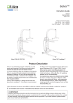
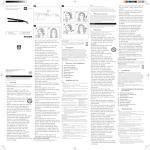
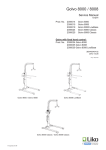
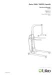
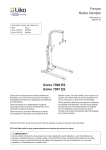
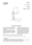
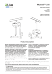
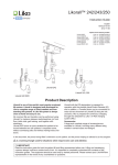
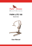
Golvo™ Instruction Guide English 7EN140107 Rev. 3 Applies to the following models: Golvo 8000 Golvo 8008 Golvo 8008 LowBase™ Golvo 8000/8008 Prod. No. 2000034 Prod. No. 2000035 Prod. No. 2000039 Golvo 8008 LowBase™ Product Description Golvo 8000 and 8008 are advanced mobile lifts intended mainly for use in health care, intensive care, rehabilitation and habilitation. The models listed above differ in size and lifting height. With a unique lift strap design and parallel widening of WKHOHJV*ROYRLVDQHDV\WRXVHDQGÀH[LEOHDLGIRU daily transfers of adults and children, for instance, lifting WRDQGIURPZKHHOFKDLUEHGWRLOHWDQGÀRRUIRUVWDQG and gait training, and transfer from car. Service is facilitated by Liko Diagnostic System™, a monitoring system which continually registers operating data and indicates when the lift is in need of service. The battery is of environmentally friendly NiMH type. *ROYR/RZ%DVHKDVDGHVLJQZLWKH[WUDORZEDVH intended for use in combination with stretchers or other equipment where space for the lift base is limited. ,QGLYLGXDO¿WWLQJRIWKHVOLQJDQGRWKHUOLIWLQJDFFHVVRULHV to the patient is of the utmost importance for optimal performance and safety when using the lift Horizontal lifting is also possible with any of the Liko stretchers. is a warning triangle used for situations which require extra care and attention. In this document, the person being lifted is referred to as the patient, and the person helping them is referred to as the caregiver. IMPORTANT! Read the instruction guide for both the patient lift and lifting accessories before use. Lifting and transferring a person always involves a certain level of risk. It is important to completely understand and adhere to the contents of the instruction guides. The equipment should only be used by trained personnel. Please contact your Liko/Hill-Rom representative in the event of any uncertainties or questions. Table of Contents Safety Instructions ........................................................................2 'H¿QLWLRQV .....................................................................................3 Technical Data ..............................................................................3 Dimensions ...................................................................................4 Assembly ......................................................................................5 Disassembly .................................................................................7 Operation ......................................................................................8 Charging the Batteries ................................................................13 0D[LPXP/RDG ...........................................................................14 Recommended Lifting Accessories ............................................14 Simple Troubleshooting ..............................................................17 Inspection and Maintenance.......................................................18 NOTE! This instruction guide contains important information for users of the product. All those who use the product should review and fully understand and adhere to the contents of the instruction guide. Remember to keep the instruction guide in a place where it is always available to those using the product. Warning! &HUWDLQHQYLURQPHQWVDQGFRQGLWLRQVFDQOLPLWWKHFRUUHFWXVHRIWKHPRELOHOLIWVLQFOXGLQJWKUHVKROGVXQOHYHOÀRRU VXUIDFHVYDULRXVREVWDFOHVDQGH[WUDWKLFNFDUSHWV7KHVHHQYLURQPHQWVDQGFRQGLWLRQVFDQFDXVHWKHZKHHOVRIWKH PRELOHOLIWQRWWRUROODVLQWHQGHGSRVVLEOHLPEDODQFHLQWKHPRELOHOLIWDQGLQFUHDVHGH[HUWLRQE\WKHFDUHJLYHU,I\RX DUHXQFHUWDLQWKDW\RXUFDUHHQYLURQPHQWIXO¿OVWKHUHTXLUHPHQWVIRUFRUUHFWXVHRIWKHPRELOHOLIWSOHDVHFRQWDFW\RXU Liko/Hill-Rom representative for further advice and assistance. Safety Instructions Before using WKH¿UVWWLPH make sure that: WKHOLIWLVDVVHPEOHGLQDFFRUGDQFHZLWKWKHDVVHPEO\LQVWUXFWLRQV WKHOLIWLQJDFFHVVRU\LVSURSHUO\DWWDFKHGWRWKHOLIW WKHEDWWHULHVKDYHEHHQFKDUJHGIRUDWOHDVWKRXUV \ RXKDYHUHDGWKHLQVWUXFWLRQJXLGHVIRUWKHOLIWDQGOLIWLQJDFFHVVRULHV S HUVRQQHOXVLQJWKHOLIWDUHLQIRUPHGRIWKHFRUUHFWRSHUDWLRQDQGXVHRIWKHOLIW Before lifting, always make sure that: WKHOLIWLQJDFFHVVRU\LVVHOHFWHGDSSURSULDWHO\LQWHUPVRIW\SHVL]HPDWHULDODQGGHVLJQ ZLWKUHJDUGWRWKHSDWLHQW¶VQHHGV WKHOLIWLQJDFFHVVRULHVDUHQRWGDPDJHG WKHOLIWLQJDFFHVVRU\LVFRUUHFWO\DWWDFKHGWRWKHOLIW WKHOLIWVWUDSLVQRWWZLVWHGRUZRUQDQGFDQPRYHLQDQGRXWRIWKHOLIW WKHOLIWLQJDFFHVVRU\KDQJVYHUWLFDOO\DQGFDQPRYHIUHHO\ WKHOLIWLQJDFFHVVRU\LVFRUUHFWO\DQGVDIHO\DSSOLHGWRWKHSDWLHQWLQRUGHUWRSUHYHQWLQMXULHV WKHODWFKHVDUHLQWDFW0LVVLQJRUGDPDJHGODWFKHVPXVWDOZD\VEHUHSODFHGZLWKQHZRQHV WKHVOLQJ¶VVWUDSORRSVDUHFRUUHFWO\FRQQHFWHGWRWKHVOLQJEDUKRRNVZKHQWKHVOLQJVWUDSLVH[WHQGHG but before the patient is lifted from the underlying surface. Unbalanced lifting poses a tipping risk and may damage the lift equipment! 1HYHUOHDYHDSDWLHQWXQDWWHQGHGGXULQJDOLIWLQJVLWXDWLRQ *ROYR/RZ%DVHKDYHEHHQWHVWHGE\DQDFFUHGLWHGWHVWLQJLQVWLWXWHDQGIXO¿OWKHUHTXLUHPHQWV VSHFL¿HGLQWKH0HGLFDO'HYLFH'LUHFWLYHIRUFODVVSURGXFWV 0''((& Golvo 8000/8008/8008 LowBase™ comply with the requirements in EN ISO 10535:2006, IEC 60601-1, EN 60601-1-2, ANSI/AAMI ES60601-1 and CAN/CSA C22.2 no. 60601-1. 7KHOLIWPXVWQRWEHPRGL¿HGXQGHUDQ\FLUFXPVWDQFH,I\RXKDYHDQ\TXHVWLRQVSOHDVHFRQWDFW Liko/Hill-Rom. Particular care must be observed when using strong sources of potential disturbance, such as diathermy, etc, so that diathermy cables are not positioned on or near the lift. If you have questions, please consult the responsible assistive-device technician or the supplier. 7KHOLIWPD\QRWEHXVHGLQDUHDVZKHUHÀDPPDEOHPL[WXUHVPD\RFFXUIRUH[DPSOHLQDUHDVZKHUHÀDPPDEOH goods are stored. *ROYR(15HY 2 w w w . l i k o . com 'H¿QLWLRQV *ROYR 1 18 17 2 16 3 1. Lift Strap 2. Sling bar with latches 3. Retractable armrests 4. Parking panel for sling bar 5. &RQWUROER[,5UHFHLYHU 6. Holder for Quick Reference Guide and color code for sling sizes 15 7. Product decal 8. Mast with inbuilt motor 6 9. Front wheels 7 10. Base 4 5 14 13 11. Rear wheels with brakes 8 12. 0RWRUIRUEDVHZLGWKDGMXVWPHQW Forward direction &RQWUROER[ZLWKHPHUJHQF\VWRSEXLOWLQFKDUJHU DQGSHUDWLRQSDQHO HOHFWULFDOHPHUJHQF\ORZHULQJ UDLVLQJ 12 11 14. Battery 9 10 15. Hand control 16. Handles *ROYR/RZ%DVH 17. (PHUJHQF\/RZHULQJ PHFKDQLFDO 18. Lift arm ([WUDORZEDVH *ROYR/RZ%DVH 19 Technical Data Maximum load: 200 kg OEV Material: Anodised aluminium Weight: NJ OEV NJ OEV /RZ%DVHNJ OEV Heaviest removable part: NJ OEV NJ OEV /RZ%DVHNJ OEV Wheels: Turning diameter Operating forces, Buttons on hand control: 2.4 N controls: Button on display: 4 N )URQWPP LQ WZLQZKHHOV *ROYR/RZ%DVHPP LQ WZLQ wheels. 5HDUPP LQ WZLQZKHHOV with brakes. Mechanical and electrical Lifting Speed no load 7ZRVSHHGVPPV LQV and PPV ,QV /LIWLQJLQWHUYDO PP LQ KHLJKWDGMXVWDEOH 6RXQGOHYHO G% $ Protection class: IP X4 *ROYR(15HY 24 V Intermittent power: ,QW2SDFWLYHRSHUDWLRQPD[ 2 min. Only 10% of a given length of time may be active, but no more than 2 min. Battery: NiMH cells, 2.2 Ah. New batteries provided by the supplier. Battery charger: CBL20002, built-in, 100-240 V AC, 50-60 Hz, PD[P$ Lift motor: 24 V, 8.2 A Motor for basewidth adjustment: 24 V, 5.5 A *ROYRPP LQ *ROYRPP LQ Golvo 8008 LowBase: 1330 mm LQ Emergency ORZHULQJGHYLFH Electrical data: The device is intended for use indoors. Type B, in accordance with the electrical shock protection class. Class II equipment. Protected by Patent 3 w w w . l i k o . com Dimensions 7RSYLHZ **700 mm (28 in) /DWHUDOYLHZ M D C A D2 O LPD[ Lmin EG **600 mm (24 in) E F1 F *ROYR/RZ%DVH B3 B2 B1 B B4 Maximum reach Measurements Measurements in mm / in A Model C B1 B2 B3* B4 *ROYR 1995 1360 1115 800 435 435 - 938 654 826 *ROYR 2090 1455 1185 870 480 480 - 1020 735 *ROYR Low- 2090 1455 1185 870 Base 480 480 600 1028 745 B2 B3* B4 Model PD[ min. A PD[ min. B D B B1 D2* E F F1 G 543 0 975 105 25 840 1735 907 623 0 1100 105 25 940 907 623 0 1100 60 / 105 22 940 D2* E F F1 G PD[ min. PD[ min. C LPD[ Lmin M O 475 440 362 1860 600 436 391 1860 600 436 391 M O . D PD[ min. PD[ min. LPD[ Lmin *ROYR 78.5 53.5 43.9 31.5 17.1 17.1 - 36.9 25.7 32.5 21.4 0 38.4 4.1 1.0 33.0 68.3 18.7 17.3 12.8 *ROYR 82.3 57.3 46.6 34.2 18.9 18.9 - 40.2 28.9 35.7 623 0 43.3 4.1 1.0 37 73.2 23.6 17.2 15.4 *ROYR LowBase 82.3 57.3 46.6 34.2 18.9 18.9 23.6 40.5 29.3 35.7 623 0 43.3 2.4 / 4.1 0.9 37 73.2 23.6 17.2 15.4 7KHOLIWLQJLQWHUYDOPP LQ LVKHLJKWDGMXVWDEOHVHHS Note: When changing to other lifting accessories check that the lift still achieves desired lifting height. * Reference measurement according to Standard EN ISO 10535:2006 *ROYR(15HY 4 w w w . l i k o . com Assembly %HIRUHDVVHPEO\PDNHVXUH\RXKDYHWKHIROORZLQJSDUWVDQGWRROV L LIWPDVWZLWKFRQWUROER[DQGKDQGFRQWUROVOLQJEDU with latches, 2 M6 screws Armrest. BDVHZLWKZLGWKDGMXVWPHQWPRWRU %DWWHU\ T ools: 4, 5 mm Allen keys. Bag containing instruction guide, quick reference guide, handle reinforcement for emergency lowering, charger cable, charger connector cable, FDEOHOLGZLWKVFUHZV Lock the wheels on the base before starting to assemble the lift. A B 8QVFUHZDQGUHPRYHWKHWUDQVSRUWDWLRQJXDUG PHWDOSODWH at the bottom of the lift mast. Remove the transportation guard, its attachment screws and the red information decal. $ 3RVLWLRQWKHOLIWPDVWEHWZHHQWKHWZREODFNSODVWLFSOXJV on the base cross member. % 7KHQSXVKWKHPDVWIRUZDUGVDVLQWKH¿JXUHDERYH so that it hooks onto the cross member. 2. Screw the two provided M6 screws into the upper holes on the lift mast. No screws in the lower holes! B A $ 3ODFHWKHDUPUHVWSDUWLQWKHDWWDFKPHQWRQWKHOLIWPDVW starting with the lower groove. % / RZHUDQGORDGWKHDUPUHVWXQWLOLWKRRNVRQWRWKHXSSHU groove on the armrest part. Do not remove any of the pre-assembled M8 screws completely, but it may be necessary to loosen them. *ROYR(15HY 5 4. Secure the armrest by tightening the two preassembled M8 screws. w w w . l i k o . com 1 2 3 6. Insert the cables through the opening in the cable lid. Push the lid up and secure with the provided $OOHQNH\DQGVFUHZV 5. Connect the cables as follows: - Charger cable to socket 1. - Cable from lift motor to socket 2. &DEOHIRUPRWRUIRUEDVHZLGWKDGMXVWPHQW to socket 3. 7. Hang the hand control on the handle. 10. Place the quick reference guide in the holder on the lift mast. *ROYR(15HY 8. Place the battery in its EUDFNHWLQWKHFRQWUROER[ Check that the battery is secured in its position. 9. Press the handle reinforcement LQWRSODFHZLWKWKHWH[W³(PHUJHQF\ lowering” visible on the emergency lowering handle. 11. Release the emergency stop 12. Before initial use, charge the by turning the button in the battery by plugging the charger direction indicated by the arrows cable into the connector cable. on the button. Then plug the charger cable into an electrical socket 9$& The battery charges fully in about 5 hours. 6 w w w . l i k o . com 13. Place the charger cable on the hook provided on the mast after completed charging. After assembly and charging, ensure that: The motion of the lift arm corresponds to the buttons on the hand control/operation panel. The emergency lowering functions are working PHFKDQLFDODQGHOHFWULFDO The wheel brakes are working. TKHEDVHZLGWKDGMXVWPHQWZRUNV The batteries are charged. Disassembly %HJLQE\UHPRYLQJWKHVOLQJEDURURWKHUDFFHVVRU\WKDWLV¿WWHGWRWKHOLIW 2. Remove the armrest holder as described below: $'RQRWUHPRYHMXVWloosen the two M8 screws in the armrest holder on either side of the lift mast. B. Remove the armrest holder using two screwdrivers. Place screwdrivers inside on top of handlebar and pull up simultaneously as illustrated. /RRVHQWKHFDEOHVIURPWKHFRQWUROER[VHHS 4. Remove the mast as described below: :KHQWKHPDVWKDVEHHQGHWDFKHGIURPWKHEDVHLWPXVWEHVXSSRUWHGWRSUHYHQWLWIURPIDOOLQJ. B. Then screw the safety screws into the lower holes on the lift mast. This releases the mast from the base, and it can now be removed. A. Unscrew both the safety screws in the upper holes on the mast. *ROYR(15HY 7 w w w . l i k o . com Operation The lift can be operated with the hand control or from the operation panel. Up / DownDGMXVWWKHOLIWLQJPRWLRQ XSGRZQ VORZO\ Up Out / In, DGMXVWWKHEDVHZLGWK up, (slowly) Down down, (slowly ) Base wider Base narrower Cable Hand Control The direction of the arrows applies when the hand control is held as shown in the picture. The lifting and base movement stops as soon as the push button is released. Operation Panel There are 6 push buttons on the panel. For the symbols and indicator lights of the operation panel, please see below. Symbols and indicator lights (/LNR'LDJQRVWLF6\VWHP on the operation panel: IR - communication, (green light) - Receives/Sends IR signals. 6HUYLFHLQGLFDWLRQ RUDQJHOLJKW - Illuminates when service is needed. Contact the service technician authorized by Liko/Hill-Rom. 2YHUORDG RUDQJHOLJKW ,OOXPLQDWHVLIWKHOLIW¶VPD[LPXPORDG LVH[FHHGHGDQGWKHOLIWVWRSV7KH indicator turns off after 3 secs., and the lift operates again. Expected Life Time (ELT) UHGOLJKW - When the light ÀDVKHV during lifting, the Liko Diagnostic System™ indicates that the H[SHFWHGOLIHWLPHfor the lift is approaching its end. Contact the service technician authorized by Liko/Hill-Rom. If the ELT light proceeds to shine continuously when liftingWKHOLIWVKRXOGEHWDNHQRXWRIVHUYLFHContact WKHVHUYLFHWHFKQLFLDQDXWKRUL]HGE\/LNR+LOO5RP $FWLYDWH Reset Lock Unlock Locking the Wheels The rear wheels can be locked to prevent rotating and turning. The locking/unlocking of the wheels is done with the foot. Locked wheels during lifting can increase the risk of tipping. NOTE: When lifting, the wheels should be unlocked so that the lift can be moved to the patient’s centre of gravity. The wheels should be locked, however, if there is a risk of the lift rolling into the patient, IRULQVWDQFHZKHQOLIWLQJIURPWKHÀRRU Emergency stop Activate: 3UHVVWKHUHGEXWWRQRQWKHFRQWUROER[ Reset: Turn the button in the direction indicated by the arrows on the button. *ROYR(15HY 8 w w w . l i k o . com Electrical Emergency Lowering/Raising Use the arrow buttons on the operation panel XSRUGRZQ XQWLOWKHSDWLHQWEHLQJOLIWHGLVRQ D¿UPVXUIDFHDQGthe strap loops of the sling can be unhooked. Mechanical Emergency Lowering Emergency lower by moving the handle marked ³(PHUJHQF\ORZHULQJ´XSDQGGRZQ5HSHDWWKHPRWLRQ until the patient being lifted LVRQD¿UPVXUIDFHGUDZ down the sling bar manually and continue to pump the handle until the sling bar is low enough to enable the sling’s strap loops to be unhooked. a After mechanical emergency lowering / 5HVWRULQJWKHOLIWLQJOHYHO If the lift strap has been lengthened due to using the emergency lowing function, the lift interval height will be ORZHUWKDQSUHYLRXVO\7RUHVWRUHPD[LPXPOLIWLQJKHLJKW the lift strap must be reset to its original length. Do as follows: 1. Remove any load / weight from the strap above the emergency lowering device. Do this by either placing the sling bar above the lift arm or by another person holding the sling bar up so that the strap hangs loose. 2. /RZHUDQGUDLVHWKHKDQGOHPDUNHG³(PHUJHQF\ lowering” with your left hand. At the same time tension WKHVWUDSE\WXUQLQJWKHEODFNNQRE D FORFNZLVHZLWK your right hand. Repeat this procedure until the red mark RQWKHVWUDSLVMXVWDERYHWKHHPHUJHQF\ORZHULQJGHYLFH *ROYR(15HY $GMXVWPHQWRIWKHOLIWLQWHUYDOOHYHO If it is necessary to reach a lower level with the sling bar, this can be arranged by lengthening the lift strap using the mechanical emergency lowering device. Do not lengthen the strap more than necessary as the highest obtainable lifting level is also affected. $QH[DPSOHRIZKHQLWZRXOGEHDGYDQWDJHRXVWRORZHU WKHOLIWLQWHUYDOLVZKHQOLIWLQJIURPWKHÀRRUXVLQJDVOLQJ whose strap loops do not reach up to the sling bar hooks when the lift is in its lowest position. Do as follows: Push down the red emergency lowering KDQGOHDWWKHVDPHWLPHDVORDGLQJWKHVOLQJEDU SXOO GRZQWKHVOLQJEDUZLWK\RXURWKHUKDQG 7KLVH[WHQGV the strap and the sling bar is lowered. Repeat until the required strap length is obtained. 9 w w w . l i k o . com WRONG! support position rest position Armrest To use the armrest you need to rotate it from the YHUWLFDO UHVWSRVLWLRQXSWRWKH KRUL]RQWDO VXSSRUW position. The armrest have two purposes: to help the patient feel more secure and facilitate for the caregiver when moving the lift. When using the lift to transfer a patient between rooms, the armrest should be set in the support position! Parking the sling bar When the lift is not in use or is being moved without DORDGLWFDQEHEHQH¿FLDOWRSODFHWKHVOLQJEDULQWKH parking panel. The parking panel is intended for parking Universal 6OLQJ%DUVDQG DOOPRGHOV When the sling bar is parked in the parking panel, the lift should not be raised since this could be dangerous and cause personnel injury or damage to the lift if the sling bar should release and swing out from the panel. )LJXUH Installation of Latches After installation, ensure that the spring loaded clip is taut against the sling bar and moves freely in the sling bar hook. *ROYR(15HY )LJXUH Lift correctly! Before each lift, make sure that: – the Sling loops at opposite sides of the Sling are at the same height – all the Sling loops are fastened securely in to the Sling bar hooks – the Sling bar is level during the lift, see Figure 1. ,I6OLQJEDULVQRWOHYHO VHH)LJXUH ORZHUWKH XVHUWRD¿UPVXUIDFHDQGDGMXVWDFFRUGLQJWRWKH Sling in use Instruction Guide. An improper lift can be uncomfortable for the user and cause damage to the lift equipment! (see )LJXUH 10 w w w . l i k o . com Position of the Lift when Lifting From/To: Bed Chair/Toilet Seat Floor NOTE: Place a pillow under the patient’s head for increased performance and comfort. Always have the wheels locked ZKHQOLIWLQJIURPWKHÀRRU Transfer from car Ensure that the lift used for car transfers is always stored and charged indoors. Outdoor operation should be kept WRDPLQLPXP8VLQJWKHOLIWLQKDUVKFRQGLWLRQVVXFKDVUDLQVQRZRUH[WUHPHFROGPD\LPSDFWWKHSHUIRUPDQFH of the lift immediately. Prerequisites Transfer from car is applicable from the front and rear with the patient in a seated position. The caregiver must assess that transfer from the car is achievable. Considerations should be made regarding the status of the patient VWDWXVFRQGLWLRQKHLJKWDQGZHLJKWSRVLWLRQDQGDFFHVVLELOLW\ WKHUHODWLYHVL]HRIWKHFDUDQGSRVLWLRQRIWKHOLIW equipment. The ground surface of the transfer area should be level, hard and smooth and free from gravel, debris, ice and potholes. Two caregivers are recommended for this task. A gurney or a wheel chair should be in the immediate vicinity of the car when performing the lift. Recommended slings for car transfer are the Universal Sling PRGHOV DQGWKH+LJK%DFN6OLQJ PRGHOV )RUFRUUHFWVOLQJDSSOLFDWLRQFRQVXOWWKHVOLQJ instruction guide. Do as follows: 1. Apply the sling according to the sling instruction guide, a HandySheet or Tube can be used to reduce friction. One caregiver may assist from inside the car if necessary. *ROYR(15HY 2. Position the lift as perpendicular as possible to the car, with the car door open. Keep the lift arm outside the car and the wheels of the lift unlocked. 11 w w w . l i k o . com 3. Attach sling loops to the sling bar. Ensure the correct application of sling loops to the sling bar. Raise the lift to apply more tension on the sling. Rotate the patient toward the door opening and guide the legs of the patient out of the car. Apply friction reducing devices if necessary. 4a. One caregiver must guide the sling bar and patient out of the car and ensure that the head of the patient is JXLGHGVDIHO\ZKLOHH[LWLQJWKHFDU7KHRWKHUFDUHJLYHU will need to raise the lift while simultaneously pulling the lift backwards. 4b. Notice the correct grip on the sling bar to avoid SLQFKLQMXULHVWRWKHFDUHJLYHUDVWKHVOLQJEDULVJXLGHG out of the car. Avoid placing hands between the sling bar and the door frame of the car. 5. Removal of the patient from the car is complete, continue the transfer to a wheel chair or gurney. *ROYR(15HY 12 w w w . l i k o . com Charging the Batteries 2 3 4 1 Battery Capacity &KHFNWKHEDWWHU\FDSDFLW\E\SUHVVLQJWKHLEXWWRQ 7KHIROORZLQJ information can be read: *UHHQOLJKW More than 50% of the battery capacity remains. 3 - Orange light: 25–50% of the battery capacity remains. 4 - Orange light: 0–25% of the battery capacity remains. 7KHLQGLFDWLRQODPSVOLJKWXSIRUDERXWKDOIDPLQXWHWKH\WKHQJRRXW The battery capacity is also shown when the lift is in use. 7RREWDLQPD[LPXPVHUYLFHOLIHLWLVLPSRUWDQWWRFKDUJHWKHEDWWHULHVUHJXODUO\:HUHFRPPHQGFKDUJLQJDIWHUXVH of the lift or every night. 0D[LPXPFKDUJHLVREWDLQHGDIWHUDERXWKRXUV:KHQWKHEDWWHULHVDUHfully charged, WKHFKDUJHUVZLWFKHVWR³WULFNOHFKDUJLQJ´DXWRPDWLFDOO\ 'XULQJFKDUJLQJWKHOLJKWVVKLQHDOWHUQDWLYHO\ RUDQJHRUDQJHJUHHQ )RUGHHSO\GLVFKDUJHGEDWWHULHVWKHLQGLFDWLRQ for initiated charging can be delayed a few minutes. &RPSOHWHGFKDUJLQJLVLQGLFDWHGE\DÀDVKLQJJUHHQOLJKW:KHQ the operation time is noticeably shortened, the batteries probably need changing. Stop charging and switch batteries. The lift cannot be charged with the emergency stop engaged. 1HYHUFKDUJHEDWWHULHVLQDZHWDUHD NOTE! If the lift is not to be used for a long period, the battery should be connected to charging. Charging With built-in charger: &KHFNWKDWWKHFKDUJHUFDEOHLVFRQQHFWHGWRWKHFRQWUROER[RXWOHW see p. 6. &RQQHFWWKHFKDUJHUFDEOHWRDQHOHFWULFDORXWOHW 9$& &RPSOHWHGFKDUJLQJLVLQGLFDWHGE\DÀDVKLQJJUHHQOLJKWRQWKHEDWWHU\ If the charger cable is permanently stretched, it should be replaced in order to minimize the risk of the cable getting stuck and breaking. NOTE! The lift cannot be used when the charger cable is plugged into a wall socket. Old batteries are to be deposited at the nearest recycling station or given to personnel authorized by Liko/Hill-Rom. *ROYR(15HY 13 w w w . l i k o . com Maximum Load 'LIIHUHQWPD[LPXPORDGVPD\DSSO\WRGLIIHUHQWSURGXFWVRQWKHDVVHPEOHGOLIWXQLWVOLQJEDUVOLQJDQGDQ\RWKHU DFFHVVRULHVXVHG)RUWKHDVVHPEOHGOLIWXQLWLQFOXGLQJDFFHVVRULHVWKHPD[LPXPORDGLVDOZD\VWKHORZHVW PD[LPXPORDGUDWLQJIRUDQ\RIWKHFRPSRQHQWV$*ROYRWKDWLVDSSURYHGIRUNJ OEV FDQEHHTXLSSHG ZLWKDOLIWLQJDFFHVVRU\WKDWLVDSSURYHGIRUNJ OEV ,QWKLVFDVHWKHPD[LPXPORDGRINJ OEV applies to the assembled lift unit. Study the markings on the lift and lifting accessories or contact your Liko/Hill-Rom representative if you have any questions. Recommended Lifting Accessories 8VLQJOLIWLQJDFFHVVRULHVRWKHUWKDQWKRVHDSSURYHGFDQHQWDLODULVN Generally recommended sling bars and accessories for Golvo mobile lifts are described below. When changing a sling bar or other lifting accessories, the highest possible lifting height of the lift is affected. %HIRUHFKDQJLQJOLIWLQJDFFHVVRULHV\RXVKRXOGDOZD\VHQVXUHWKDWWKHOLIWDIWHUFKDQJHFDQIXO¿OWKHGHVLUHG lifting height in order to manage the lifting situations for which the lift is to be used. To select suitable slings and other lifting accessories, please see the ³Golvo” and ³/LIWLQJDFFHVVRULHV´EURFKXUHV For additional guidance in selecting a sling, study the operating instructions for the respective sling models. 7KHUH\RXZLOODOVR¿QGJXLGDQFHIRUFRPELQLQJ/LNR¶VVOLQJEDUVZLWK/LNR¶VVOLQJV Contact your Liko/Hill-Rom representative or visit www.liko.com for advice and information on Liko’s product range. 6OLQJ%DU0LQL 0D[NJ OEV Prod. no. 3156005 8QLYHUVDO6OLQJ%DU 0D[NJ OEV Prod. No. 3156074 8QLYHUVDO6OLQJ%DU 6WDQGDUGRQ*ROYR 0D[NJ OEV Prod. No. 3156075 8QLYHUVDO6OLQJ%DU 0D[NJ OEV Prod. No. 3156076 8QLYHUVDO7ZLQ%DU7ZLQ 0D[NJ OEV Prod. No. 3156077 8QLYHUVDO6LGH%DUV including bag 0D[NJ OEV Prod. No. 3156079 6OLQJ&URVVEDU 0D[NJ OEV Prod. No. 3156021 6OLQJ&URVVEDU 0D[NJ OEV Prod. No. 3156018 6OLQJ%DU&RYHU3DGG\ ¿WV8QLYHUVDO6OLQJ%DUV DQGDVZHOODV6OLQJ%DU6OLP Prod. No. 3607001 * also available equipped with Quick-Release Hook. *ROYR(15HY 14 w w w . l i k o . com Bag for SlingBars Prod. No. 2001025 Quick-Release Hook Liko’s Quick-Release Hooks are a system for quick change of lifting accessories on Liko’s mobile and stationary lifts. The Golvo must be equipped with Q-link in order to be used with the Quick-release Hook. 7KH4XLFN5HOHDVH+RRN8QLYHUVDO¿WVWKH8QLYHUVDO%DUV DQG SURGQR 4XLFN5HOHDVH+RRN7'0¿WV WKH6OLQJ%DU0LQL SURGQR 6OLQJ&URVVEDUDQG SURGQRDQG DQG8QLYHUVDO7ZLQ%DU SURGQR 6HHWKH³*XLGHWR/LNR¶V4XLFNRelease Hook System”, which can be downloaded from our website www.liko.com, or contact your Liko/Hill-Rom representative for more information about the advantages and use of the Quick-Release Hook system. Q-link Prod. No. 31590005 Quick-Release Hook Quick-Release 8QLYHUVDO Hook TDM Prod. No. 3156508 Prod. No. 3156502 Stretchers Most stretchers in Liko’s product range can be used in combination with Golvo. Contact your Liko/Hill-Rom representative for more information. Scale For weighing patients in combination with Golvo, we recommend XVLQJ/LNR6FDOH0D[NJ OEV /LNR6FDOHLVFHUWL¿HGDFFRUGLQJWRWKH(XURSHDQ'LUHFWLYH 1$:, 1RQ$XWRPDWLF:HLJKLQJ,QVWUXPHQWV Contact your Liko/Hill-Rom representative for more information. /LNR6FDOH Prod. No. 3156228 Support Springs for Jump/Gait Training Elastic springs are available as an accessory in order to produce a softer, VSULQJ\PRWLRQIRUH[DPSOHGXULQJJDLWWUDLQLQJ7KHVSULQJVDUHDYDLODEOH in three different versions: Long, 28 cm, PD[NJSDWLHQWZHLJKWSDLU Prod. No. 3156511 Short, 22 cm, PD[NJSDWLHQWZHLJKWSDLU Prod. No. 3156512 Short, 22 cm, PD[NJSDWLHQWZHLJKWSDLU Prod. No. 3156513 See the instruction guides for Liko MasterVest, models 60 and 64 or Liko LiftPants model 92, for more information. *ROYR(15HY 15 w w w . l i k o . com Leg Protector Leg Protector Golvo 7000, grey, pair Leg Protector Golvo 7007, grey, pair Prod. No. 2006011G Prod. No. 2006012G Wall-mounted Battery Charger Prod. No. 2004108 Extra battery Prod. No. 2006107 *ROYR(15HY 16 w w w . l i k o . com Simple Troubleshooting The lift cannot be operated with the hand control. 1. Check that the emergency stop button has not been pressed. 2. Check the battery capacity. 3. Check that the charger cable is not connected to an electric outlet. 4. Check that the hand control cable is correctly connected. 5. If the lift works via the operation panel, change the Hand Control. 6. If the problem persists, please contact Liko/Hill-Rom. The lift does not work up/down with the operation panel. The base-width adjustment doesn’t work (in/out) with the operation panel. 1. Check that the emergency stop button has not been pressed. &KHFNWKDWWKHFDEOHVWRWKHFRQWUROER[DUHFRQQHFWHG correctly. 3. Check that the charger cable is not connected to an electric outlet. 4. Check the battery capacity. 5. If the problem persists, please contact Liko/Hill-Rom. The charger doesn’t work. 1. Check that the emergency stop button has not been pressed. 2. Check that the charger cables are connected correctly. 3. Make sure that the battery is properly attached. 4. If the problem persists, please contact Liko/Hill-Rom. The lift is stuck in the high position. 1. Check that the emergency stop button has not been pressed. 2. Check the battery capacity. 3. Check that the hand control cable is connected correctly. 4. Electrical emergency lowering, use the operation panel WRORZHUWKHSDWLHQWRQWRD¿UPVXUIDFH 5. Use the mechanical emergency lowering device to lower WKHSDWLHQWRQWRD¿UPVXUIDFH 6. If the problem persists, please contact Liko/Hill-Rom. The lift does not reach maximum lifting height. 1. Check that the lifting interval level is correctly set. 2. If the problem persists, please contact Liko/Hill-Rom. If any noises are heard. Contact Liko/Hill-Rom. *ROYR(15HY 17 w w w . l i k o . com Inspection and Maintenance Care and Maintenance For trouble-free use, certain details should be checked each day the lift is used: ,QVSHFWWKHOLIWDQGFKHFNWRPDNHVXUHWKDWWKHUHLVQRH[WHUQDOGDPDJH &KHFNWKHVOLQJEDUDWWDFKPHQW &KHFNWKHOLIWVWUDSIRUZHDUDQGWRHQVXUHWKHVWUDSLVQRWWZLVWHG &KHFNWKHIXQFWLRQDOLW\RIWKHODWFKHV &KHFNWKHLQWHJULW\RIWKHOLIWLQJPRWLRQDQGWKHEDVHZLGWKDGMXVWPHQW C heck that the lifting interval level is set correctly and that the emergency lowering is working as it should ERWKWKHHOHFWULFDODQGWKHPHFKDQLFDO Charge the batteries each day the lift is used and make sure the charger works. When necessary, clean the lift with a moist cloth and check that the wheels are free from dirt. Find more detailed information regarding cleaning and disinfection of your Liko/Hill-Rom product in the document Care and Maintenance at our website: www.liko.com. The lift should not be exposed to running water. 6HUYLFH A periodic inspection of the lift should be carried out at least once per year. Periodic inspection, repair and maintenance may be performed only in accordance with the Liko VHUYLFHPDQXDOE\SHUVRQQHODXWKRUL]HGE\/LNR+LOO5RPDQGXVLQJRULJLQDO/LNRVSDUHSDUWV Expected Life Time 7KHSURGXFWKDVDQH[SHFWHGVHUYLFHOLIHRI\HDUVZKHQFRUUHFWO\KDQGOHGVHUYLFHGDQGSHULRGLFDOO\LQVSHFWHG in accordance with Liko’s instructions. Transport and Storage During transportation, or when the lift is not to be used for a long time, the emergency stop should be engaged. The environment where the lift is transported and stored should have a temperature of 10°C to 40°C ±) DQGDUHODWLYHKXPLGLW\RIWR7KHDLUSUHVVXUHVKRXOGEH±K3D Recycling For instructions on how to recycle your Liko/ Hill-Rom product, please visit our website: www.liko.com. Product Changes Liko products undergo continuous development, which is why we reserve the right to make product changes without prior notice. Contact your Liko/Hill-Rom representative for advice and information about product upgrades. Design and Quality by Liko in Sweden +LOO5RPV0DQDJHPHQWV\VWHPDUHFHUWL¿HGLQDFFRUGDQFHZLWK,62DQGLWVHTXLYDOHQWIRUWKHPHGLFDO GHYLFHLQGXVWU\,62+LOO5RPV0DQDJHPHQWV\VWHPLVDOVRFHUWL¿HGLQDFFRUGDQFHZLWKHQYLURQPHQWDO standard ISO 14001. w w w . l i k o . com Manufacturer: Liko AB Nedre vägen 100 SE-975 92 Luleå Sweden © Copyright Liko AB 2014 June 6HUYLFH$JUHHPHQW Liko/ Hill-Rom offers the opportunity to enter into service contracts for the maintenance and regular inspection of your Liko/ Hill-Rom product.