1
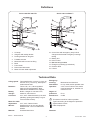
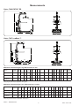
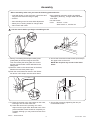
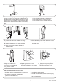
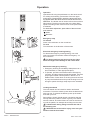
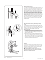
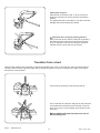
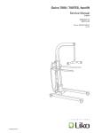
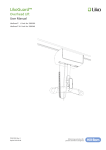
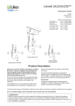
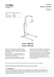
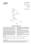
Golvo™
Instruction Guide
English
7EN140102-03
2009-07-03
Applies to the following models:
Golvo 7000 ES
Golvo 7007 ES
Golvo 7007 LowBase™
Golvo 7000 ES/ 7007 ES
Prod. No. 2000009
Prod. No. 2000010
Prod. No. 2000061
Golvo 7007 LowBase™
Product Description
Golvo is an electrically powered mobile lift, i.e., both
raising and lowering of the lift arm and width adjustment of the base are done with electric motors.
To ensure maximum safety for caregivers and patients,
Golvo is equipped for both mechanical and electrical
emergency lowering. All Golvo lifts are equipped with
convenient armrests, to assist both the caregiver and
the patient. If needed, the armrests can be folded down
into a support position.
Golvo is also available in a design with an extra low
base; Golvo LowBase™. This model is recommended
for lifting to and from beds/barrack-beds that have a
ground clearance of 58-110 mm (2.28-4.3 inch.).
Golvo can be used in most lifting situations: for
example, between bed/wheelchair, to/from the toilet,
in bath and shower, to/from the floor, for weighing
patients and for horizontal lifting.
A comprehensive range of accessories are available
for Golvo, including sling bars of different widths,
slings in many sizes and fabrics, and accessories
for ambulation/gait training, static weight-bearing,
weighing patients, and for emergency room use and
horizontal lifting, etc.
In this document, the person being lifted is called the ”patient” and the person helping is called the ”caregiver”.
are triangles used to warn of situations that demand extra care and attention.
IMPORTANT!
Carefully read these instructions and the instructions for the particular lifting accessory being used. Lifting
and transferring patients always presents a potential risk. It is essential to thoroughly understand the content
of these manuals, and that only trained persons use the equipment. If you have questions, please contact
Liko or your local Liko representative.
Table of Contents
Safety Instructions .......................................................................................... 2
Definitions........................................................................................................ 3
Technical Data................................................................................................. 3
Measurements................................................................................................. 4
Assembly......................................................................................................5-6
Disassembly ................................................................................................... 7
Operation....................................................................................................8-10
Transfers from Bed........................................................................................ 10
Charging the Batteries................................................................................... 11
Maximum Load.............................................................................................. 12
Recommended Lifting Accessories..........................................................12-14
Simple Troubleshooting................................................................................ 15
Care and Maintenance.................................................................................. 16
NOTE! This instruction guide contains information that is important for users of the product. A complete understanding of the contents of the instruction guide is essential, and only personnel who are well informed should use
the equipment. Remember to keep the instruction guide readily accessible for users of the product.
Safety Instructions
Before using the lift for the first time, make certain that:
• the lift is assembled according to the instructions
• the lifting equipment is correctly applied to the lift
• the batteries have been charged for at least 6 hours
• you have read the instruction guides for the lift and lifting accessories
• personnel using the equipment have received appropriate instructions and training.
Before lifting always make certain that:
• the lift strap is not twisted or worn and that it can move freely in and out of the lift unit
•you have selected the correct type, size, material, and design of slings and accessories to safely meet the
patient’s needs
• lifting accessories are not damaged
• the lifting accessory is correctly applied to the lifting equipment
• the lifting accessory is correctly and securely applied to the patient, so that no personal injury can occur
• the sling’s strap loops are correctly fastened to the slingbar hooks when the sling strap is extended, but before
the patient is lifted from the underlying surface.
Never leave a patient unattended in a lifting situation!
Golvo 7000 ES/7007 ES/7007 LowBase are tested by an accredited testing institute and comply with the requirements of the directives for medical-technical Class 1 products (MDD 93/42/EEC).
Golvo 7000 ES/7007 ES/7007 LowBase comply with the requirements according to IEC 60601-1, IEC 60601-1-2,
EN ISO 10535, UL-60601-1 and CAN/CSA C22.2 No. 606.1.
Particular care must be taken when using strong sources of electromagnetic interference, such as diathermy, etc,
so that cables are not positioned on or near the lift. If you have questions, please consult the responsible assistive-device technician or the supplier.
This equipment is not suitable for use in the presence of flammable mixtures.
Maximum load: 200 kg (440 lbs.)
Golvo • 7EN140102-03
w w w . l i k o . com
Definitions
Golvo 7000 ES / 7007 ES
Golvo 7007 LowBase™
16
1
16
15
15
14
1
2
3
14
2
3
13
13
12
12
4
4
11
11
5
5
10
10
6
6
9
9
8
8
7
7
1. Lift strap
2. Sling bar with safety latches
3. Parking bracket for sling bar
4. Foldable armrest
5. Mast with built-in motor for lifting
6. Base
7. Front wheel
8. Rear wheel with brake
9. Motor for base-width adjustment
10.Control box with emergency stop, built-in
charger and electrical emergency lowering/
raising
11. Battery box
12.Hand control
13. Manoeuvering handles
14. Emergency lowering (mechanical)
15. Product decal
16. Lift arm
Technical Data
Lifting speed:Two speed levels: 4.8 cm/s (1.9 inch./s)
and 3.2 cm/s (1.3 inch./s); both speed
levels without load.
Batteries:Two 2.9 Ah, 12 V, valve-regulated
lead-acid gel type batteries. New
batteries are available from supplier.
Battery Built-in charger for 100-240 V AC,
charger:
50-60 Hz, max 400 mA. Lift motor: 24 V, 6.5 A. Manufactured by Liko with
planetary gearing and safety nut (prevents excessive wear).
Motor for width
adjustment:
24 V, 3.5 A. Geared motor.
Wheels: Standard front: 75 mm twin wheels.
Standard rear: 75 mm lockable twinwheels.
Material:
Anodized aluminium.
Golvo • 7EN140102-03
Emergency lowering:
Intermittent operation:
Degree of
protection:
Sound level:
Mechanical and electrical.
Int. Op 10/90, active operation max 2 min. Out of a time of 100, active must be less than 10, however not more than 2 min.
IP 43
53 dB
This device is built for indoor operation.
Type B according to the degree of protection
against electric shock.
Class ll equipment.
Patented
w w w . l i k o . com
Measurements
Golvo 7000 ES/7007 ES
Golvo 7007 LowBase™
B3
B2
H2
H
Maximum load and weight in kg. Measurement in mm.
Model
Wheel Max.
L
A
diameter load Max Max
A
Min
B
B1
B²
B³
C
D
E
F
G
H H1 H2 Weight Turning
diameter
Golvo 7000 ES
75/75
200 1750 1990 1340 540 1120
-
-
670-950 530-810 960 840 600 110 23
-
42
1240
Golvo 7007 ES
75/75
200 1850 2080 1440 580 1190
-
-
750-1020 620-900 1060 940 600 110 23
-
44
1330
Golvo 7007
LowBase™
46/75
200 1850 2080 1440 580 1190 590 600 750-1020 620-900 1060 940 600 110 20 60
46
1330
Lifting range (1260 mm) is adjustable. See page 9.
Maximum load and weight in lbs. Measurement in inches.
Model
Wheel- Max.
L
A
diameter load Max Max
A
Min
B
B1
B2
B3
C
D
E
F
G
H
H1 H2 Weight Turning
diameter
Golvo 7000 ES
2.96/2.96
440
69
78
53
21
44
-
-
26-38
21-32
38
33
24 4.3
1
-
93
49
Golvo 7007 ES
2.96/2.96
440
73
82
57
23
47
-
-
30-40
24-35
42
37
24 4.3
1
-
97
52
Golvo 7007
LowBase™
1.8/2.96
440
73
82
57
23
47 23.2 23.6 30-40
24-35
42
37
24 4.3 0.8 2.4
101
52
Lifting range (49.6 inches) is adjustable. See page 9.
Golvo • 7EN140102-03
w w w . l i k o . com
Assembly
Before assembly, make sure you have the following parts and tools:
• m
ast with lift arm, motor for lift arm, control box and
sling bar with bolt and locking nut (M8)
• armrest
• base including motor for base width adjustment
• battery box, including holder for charger cable
• hand control with cable
• bag containing instruction guide, tag marked
"Emergency lowering", charger cable and extension cable
• two M6 screws
• tools: Wrench: 17 mm Allen wrench: 4, 5 and 6 mm
Lock the wheels before you begin assembling the lift.
1. Start by unscrewing the transport safety plate (metal plate) at the lower edge of the mast. Then throw away the safety plate, the screws and the red information sticker attached to the safety plate.
A)Place the mast on the center beam of the base, between the two black plastic caps.
B)Push the mast forward as shown in the illustra-
tion above until it snaps onto the center beam.
2. Secure the mast with two M6 screws (enclosed) in the upper holes on the mast.
NOTE! Do not place any screws in the lower holes!
3. A) Place the armrest unit in the bracket on the mast,
inserting it into the lower track first.
B)Lower the armrest unit, pressing on it until it
snaps onto the upper track. Note that none of the
premounted M8 screws should be completely unscrewed, although you may need to loosen some
of them.
4. Secure the armrest by tightening the two premounted M8 screws.
Golvo • 7EN140102-03
w w w . l i k o . com
5. Assemble the sling bar (or other accessory) using M8
screws and locking nut (enclosed). Make certain to
turn the screws 2 mm (0.08 inch.) past the lock function on the nut. Do not tighten so much that the sling
bar connector cannot move in relation to the locking
plate.
B
A
6. Connect the cables to the control box as follows:
- Cable for hand control to socket number 1.
- Cable for lift motor to socket number 2.
- Cable for base motor to socket number 3.
C
7. A) Connect the extension cable for the charger
cable to the control box.
B) Insert it in the tension clip on the underside of the control box.
C) Finally, connect the charger cable to the extension cable.
8. Place the battery in its holder above the control
box. Check that the battery locks into the holder
(audible click).
BATTERY
EMERGENCY
ON
CHARGE
EMERG
ENCY
ON
CHARGE
9. M
ount the holder for the
charger cable. Hook it on the
outer edge and press down
until you hear a ’click’.
10.Reset the emergency stop by turning the button in the
direction indicated by the arrows.
11. Press the tag marked ”Emer- gency” securely into place on the
emergency lowering device.
After assembly, check to ensure that:
• wheel brakes work properly
• the width adjustment of the base works properly
•the indicator lamps on the front of the control box
light during charging.
•the lifting motions correspond with the buttons on
the handcontrol
•the emergency lowering works properly
(mechanical and electrical)
Golvo • 7EN140102-03
w w w . l i k o . com
Disassembly
1. Start by loosening the sling bar or other accessory mounted on the lift.
2. Loosen the armrest holder as described below:
A. Loosen both of the M8 screws on each side of the
mast.
B. Remove the armrest holder by using two screwdrivers.
3. Release cables for the hand control, the lift motor and the motor for base adjustment.
4. Remove the mast:
When the mast is free from the base it must be supported so it does not fall.
B. Screw in the safety screws in the lower holes on
the mast. This releases the mast from the base
and it can now be taken down.
A. Remove both of the safety screws from the upper
holes on the mast.
Golvo • 7EN140102-03
w w w . l i k o . com
Operation
BATTERY
BATTERY
EMERGENCY
ON
CHARGE
EMERGENCY
ON
CHARGE
Operation
Operate the lift using the pushbuttons on the hand control.
For raising and lowering, press either of the two upper
pushbuttons. The direction in which the arrows are pointing applies when the hand control is held as shown in the
illustration. The thicker sets of arrows refer to the maximum
lifting speed. The thinner arrows refer to the lower lifting
speed. The lifting motion ends as soon as the push button
is released.
For base-width adjustment, press either of the two lower
push-buttons:
Wider
Narrower.
Emergency stop
To activate
Press in the red button on the control box.
To reset
Turn the button in the direction of the arrows.
BATTERY
EMERGENCY
ON
CHARG
Electrical emergency lowering/raising
For electrical emergency lowering/raising, use a thin
object and press into the hole marked "Emergency" on
the control box.
The object used to press must not be too sharp
since this might cause damage to the control box!
Mechanical emergency lowering
1. Emergency lowering should always take place over a
bed, wheelchair, or other appropriate place.
2. To operate, pull down the handle marked “Emergency
Lowering” and then release the handle upward. Continue
pumping the handle until the patient in the lift is on a
stable surface. Press down on the sling bar and continue
to pump the handle down and up until the sling bar is low
enough to permit the sling's strap loops to be unhooked.
Locking the wheels
The rear wheels can be locked for rotation and lateral
movement. To lock the wheels, press down the brake lever
with your foot. To release the brakes, press up the brake
lever with your foot.
During lifting, wheels should remain unlocked so that the
lift may shift to the patient’s center of gravity. The wheels
should, however, be locked if there is a risk for the lift moving into the patient, for example when lifting from the floor.
Locked wheels during lifting increases the risk of
the lift tilting over.
CAUTION! Due to the risk for injury, never use your
hands to lock the foot brake!
Golvo • 7EN140102-03
w w w . l i k o . com
Setting the lifting range
If you need to move the sling bar closer to the floor, you
can do this by using the mechanical lowering device to
extend the lift strap. Do not extend the lift strap more
than necessary since this also influences the maximum
lifting height. For example, when lifting a patient from
the floor it may be necessary to lower the lifting range
if the sling’s strap loops do not reach the hooks of the
sling bar even when the lift arm is in its lowest position.
Do the following: Hold down the red emergency lowering handle while simultaneously pulling down the sling
bar with the other hand. This extends the lift strap and
lowers the sling bar. Continue until you achieve the
needed length.
After mechanical lowering / Resetting the lifting
range
If you extend the lift strap while testing/using the emergency lowering function, the height of the lifting range is
lowered. To reset the maximum lifting height, you must
re-establish the original length of the lift strap.
Do the following:
1. Unweight the lift strap above the emergency lowering device by placing the sling bar on the lift mast or
by having another person holding up the sling bar to
keep the lift strap slack.
2. Move the emergency lowering handle down and up
with one hand, while turning the black knob clockwise
(tightening the lift strap) with your other hand. Repeat
the action until the red mark on the lift strap is slightly
above the emergency lowering device.
a
Armrest
If needed, the armrests can be folded down into a support position. The armrests have two functions: to give
the patient a greater sense of security and to make it
easier for the caregiver to move the lift.
CAUTION! When moving a patient in the lift
between different rooms, the armrests should be
placed in the support position!
Golvo • 7EN140102-03
w w w . l i k o . com
Parking the sling bar
When the lift is not being used, or when moving an
empty lift, the sling bar can be placed in the parking
bracket.
The parking bracket is intended for use with Universal
SlingBar 350, 450 and 600 (all models).
Important when using the parking position:
Never raise the lift arm while the sling bar is parked in
the parking bracket since this might cause personal
injury or damage on the lift if the sling bar suddenly
releases from the hook and swings forward.
Transfers from a bed
Always make certain that the lift strap is vertical and parallel to the mast. To achieve this, Golvo should be placed
correctly under the bed. Adjust the width and/or change the position of Golvo in relation to the base of the bed to
achieve the correct position.
Check that the lift strap is vertical during the lift.
Do not start the lift unless the sling bar is well balanced.
An unbalanced load leads to wear and tear on the lift
strap. It may also cause instability of the lift during the
lift motion.
An unbalanced load increases the risk of
the lift tilting over!
Golvo • 7EN140102-03
10
w w w . l i k o . com
Charging the batteries
For maximum battery life, batteries must be charged regularly. We recommend charging after use or each night.
Maximum charge is reached after about 6 hours. When the batteries are fully charged, the charger disconnects
automatically. NOTE! A yellow indicator lamp on the control unit lights constantly during charging. When the
batteries are fully charged, the yellow lamp shuts off. If this lamp continues to light after 8 hours, the batteries probably need to be replaced. Discontinue charging and replace batteries.
Never charge batteries in a wet area!
If the lift is not in daily use, we recommend that the emergency stop be pressed in after the lift has been used. This
breaks the current and conserves battery power. Make sure the lift is fully charged before pressing in the emergency
stop.
Battery capacity
If the battery needs charging, a beep tone will sound
and a lamp (A) is lit on the handcontrol. There is, however, enough power left in the battery for a few more lifts.
BATTERY
A display on the control box shows the current battery
capacity. When all fields of the display are black, the
battery is fully charged. When a plug symbol appears
(see illustration), the battery must be re-charged immediately.
A
EMERGENCY
ON
CHARGE
Alternative charging procedures
Alt. A
Alt. B
EMERG
ENCY
ON
CHARG
E
EMERG
ENCY
ON
CHARG
E
With built-in charger:
With wallmounted charger or table charger housing:
Plug the charger cable into a power
socket (100-240 V AC). Check that
the yellow lamp on the control box
lights (indicates charging).
If the charger cable is stretched out
it should be replaced to avoid the
risk of the cable getting caught and
tear.
Loosen the holder for the charger cable. Remove the battery box from the
control box by loosening the locking device on top of the battery box.
Alt. A. Place the battery box on the wallmounted charger. Check that the
charger is plugged into the power socket (100-240 V AC) and that the
yellow lamp on the front of the charger lights (indicates charging).
Alt. B. Place the battery box on the charger in the table charger housing.
Check that the charger is plugged into the power socket (100-240 V AC)
and that the yellow lamp on the front of the charger lights (indicates charging).
Note! The lift does not operate when the charger cable is plugged into a power socket.
Old batteries are to be left at the nearest recycling station
or given to personnel authorized by Liko.
Golvo • 7EN140102-03
11
w w w . l i k o . com
Maximum Load
Different maximum allowable loads may apply to different products on the assembled lift system: lift, sling bar, sling
and other accessories. For the total lift system, the lowest max. allowable load indicated for the respective products
on the system always applies. For example: A Golvo that is approved for 200 kg (440 lbs.) may be equipped with a
lifting accessory that is approved for 300 kg (660 lbs.). In this case, the applicable max. load is 200 kg (440 lbs.) for
the total lift system. Study markings on the lift and lifting accessories or contact your Liko representative if you have
any questions.
Recommended Lifting Accessories
Using other lifting accessories than those recommended below may induce risk.
Sling bars and accessories recommended for use with Golvo are described below.
Changing sling bars and adding extra accessories affects the maximum lifting height of the lift. Before changing
sling bars and accessories, it is important to ensure that it will still be possible to achieve the desired lifting height
for situations in which the lift will be used.
For choice of appropriate slings and other lifting accessories, see e.g., the brochure ”Lifting accessories”. For
further guidance on choosing a sling, consult the instruction guide for the respective sling model. Here you will find
advice on suitable combinations of Liko sling bars and Liko slings.
Contact your Liko representative or visit www.liko.com for advice and information on Liko’s product range.
SlingBar Mini 220
Max 205 kg / 450 lbs.
Prod. No. 3156005
Universal SlingBar 350
Prod. No. 3156074
Max 300 kg / 660 lbs.
Universal SlingBar 450
(Standard for Viking L)
Max 300 kg / 660 lbs.
Prod. No. 3156075
Universal SlingBar 600
Max 300 kg / 660 lbs.
Prod. No. 3156076
Universal TwinBar 670 Max 300 kg / 660 lbs.
Prod. No. 3156077
Sling SideBars 450
incl. storage bag
Max 300 kg / 660 lbs.
Prod. No. 3156079
Sling Cross-bar 450
Max 300 kg / 660 lbs.
Prod. No. 3156021
Sling Cross-bar 670
Max 300 kg / 660 lbs.
Prod. No. 3156018
Golvo • 7EN140102-03
12
w w w . l i k o . com
SlingBar Cover Paddy 30
Prod. No. 3607001
(fits Universal SlingBar 350, 450 and 600
and SlingBar Slim 350)
Bag for SlingBars Prod. No. 2001025
Prod. No. 20090071
Golvo 7007 LowBase Kit This reconstruction kit enables the lift to be adapted to beds
/barrack-beds with a very low ground clearance, 58-110 mm
(2.28-4.3 inch.).
Contact Liko for more informtion.
Quick-release Hook
Liko’s Quick-release Hook system enables quick and easy
exchange of lifting accessories on Liko’s mobile and stationary
lifts. Golvo requires Q-link for use with Quick-release Hook.
Quick-release Hook Universal fits Universal SlingBar 350,
450 and 600 (Prod. No. 3156074-3156076). Quick-release
Hook TDM fits Sling Cross-bar 450 and 670 (Prod. No.
3156021 and 3156018) and Universal TwinBar 670 (Prod. No.
3156077).
When a sling bar mounted with the Quick-release Hook
system is used, the lifting height will be 33 mm (1.3 inch.)
shorter than with a permanently mounted sling bar.
See ”Guide to Liko´s Quick-release Hook System”, which can
be downloaded from our website, www.liko.com, or contact
Liko for more information on the advantages and use of the
Quick-release Hook system.
Quick-release Hook
Universal
Prod. No. 3156508
Quick-release Hook
TDM
Prod. No. 3156502
Q-link
Prod. No. 3156509
Standaid Set
Prod. No. 2001020
For patients with sufficient body stability, the Standaid Set can
be used for shorter transfers, for example between a wheelchair and a toilet, or between a bed and a wheelchair. The
patient is lifted to a semi-standing position with the help of
SafetyVest or the SupportVest, behind the back and under the
arms.
Stretchers
Most Liko stretcher models can be used in combination
with Golvo.
Contact Liko for more information.
Golvo • 7EN140102-03
Liko OctoStretch
Prod. No. 3156055
13
w w w . l i k o . com
Scale
In need of weighing patients in combination with Golvo,
we recommend LikoScale 350. Max. load 350 kg (770 lbs.).
LikoScale 350 is certified according to the european directive
NAWI 90/384 (Non Automatic Weighing Instruments).
Contact Liko for more information.
0
Support Springs
Elastic springs enable a gentler springing motion, which makes
activities such as gait training easier and more natural. Springs
are available in three different designs:
Long, max. 70 kg (154 lbs.)/pair
Prod. No. 3166511
Short, max. 70 kg (154 lbs.)/pair
Prod. No. 3166512
Short, max. 100 kg (220 lbs.)/pair Prod. No. 3156513.
For more information, see instruction guide for Liko MasterVest,
mod. 60, 64, or Liko Lift Pants, mod. 92.
Leg Protector
Leg Protector Set Golvo 7000, grey Leg Protector Set Golvo 7007, grey
Prod. No. 2006011G
Prod. No. 2006012G
Extra Battery Box
Prod. No. 2006106
Charger for Extra Battery Prod. No. 2004106
for wall mounting or for use with Table Charger Housing
Table Charger Housing
Prod. No. 2107103
excl. battery box and charger
a table charger housing for the charger when you do not wish to
mount the charger on the wall.
Golvo • 7EN140102-03
14
w w w . l i k o . com
Simple Troubleshooting
1. Check that the emergency stop button
is not pushed in (page 8).
2. Check that the cables to the control box
are correctly connected (page 6).
3. Check that the charger cable is not connected to the power socket.
4. Check that the battery is charged
(page 11).
5. Check that the contact plates of the
battery are not defective or broken off.
6. If the lift still does not work satisfactory contact Liko.
The lift does not work up/down.
Base-width adjustment does not work.
1. Check that the emergency stop button is not pushed in (page 8).
2. Check to ensure that the power socket
is power-supplied.
3. Check that the charger cable is correctly
connected (pages 6 & 11).
4. Check that the contact plates of the battery are not defective or broken off.
5. If the lift still does not work satisfactory contact Liko.
Battery charging does not work.
1. Check that the emergency stop button
is not pushed in (page 8).
2. Use the electrical emergency lowering
to safely lower the patient (see page 8).
3. Use the mechanical emergency lowering
to safely lower the patient (page 8).
4. Check that the battery is charged
(page 11).
5. If the lift still does not work satisfactory contact Liko.
The lift stops in the elevated position.
1. Check that the correct lifting range has been set (page 9).
2. If the lift still does not work satisfactory contact Liko.
The lift does not reach its maximum
lifting height.
If you hear unusual sounds or discover
wear and tear on the strap.
Golvo • 7EN140102-03
Contact Liko.
15
w w w . l i k o . com
Care and Maintenance
Care and inspection
For safe and troublefree operation, a few routine procedures should be performed every day the lift is used.
•Visually inspect the lift and check for external damage or wear
•Check the sling bar connector
•Check the lift strap for wear and make sure it is not twisted
•Check that the safety latches work properly
•Test the operation of raising and lowering and the base-width adjustment function
•Check that the correct lifting range has been set and that the emergency lowering works properly
•Charge the battery every day the lift is being used, and check the charger function
When necessary, clean the lift with a moist cloth, using common surface cleaners or disinfectants. NOTE! Do not
use cleaning products that contain phenol or chlorine, since these can eventually damage aluminum and
polyamide material.
The lift must not be exposed to running water.
Service
Golvo must be inspected at least once per year. Pay particular attention to parts that are subject to wear.
Repairs and maintenance may only be carried out according to Liko service manual, by personnel
authorized by Liko and using original Liko spare parts.
Transportation and storage
During transportation, or when the patient lift is not to be used for some time, the emergency stop button should be
pushed in. The environment where the patient lift is transported and stored should have a temperature between
10 ˚C and 40 ˚C and a humidity between 30 % and 75 %. The air pressure should be between 700 and 1060 hPa.
Recycling
For instructions on how your Liko product should be recycled, please visit our website www.liko.com.
Product changes
Liko's products are constantly being updated and refined. Liko reserves the right to change aspects of the products
without prior notice. Contact your local Liko representative for updated information and advice.
Design and Quality by Liko in Sweden
Liko is quality certified according to ISO 9001 and its equivalence for the medical device industry, ISO 13485.
Liko is also certified according to environmental standard ISO 14001.
w w w . l i k o . com
Manufacturer:
Liko AB
SE-975 92 Luleå
Sweden
[email protected]
© Copyright Liko AB 2009-07
Service agreements
Liko invites you to sign a service agreement for regular maintenance and testing of your Liko products. Contact
your local Liko representative for more information.