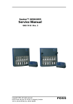
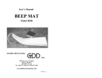
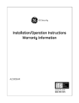
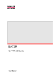
1
Service: SLR Laboratory Stirrer
glass made of ideas
Service Instructions for the
SLR Laboratory Stirrer
SLR Service eng.doc
17
Version: 03.04.2001
Service: SLR Laboratory Stirrer
glass made of ideas
Contents
Page
Contents......................................................................................................................................... 18
General way of proceeding ............................................................................................................ 19
1
Safety information.................................................................................................................. 20
2
Introduction ............................................................................................................................ 21
2.1 Required tools......................................................................................................................21
2.2 Required measuring and testing means: .............................................................................21
2.3 Setting values ......................................................................................................................21
3
Material used ......................................................................................................................... 21
4
Description of the exchangeable modules: ............................................................................ 21
4.1 Logics main board ...............................................................................................................21
4.2 Power-pack board................................................................................................................22
4.3 Connection board ................................................................................................................22
4.4 Driving unit...........................................................................................................................22
4.5 Radiation heater ..................................................................................................................23
4.6 Digital shaft encoders ..........................................................................................................23
5
Dismantling the individual modules........................................................................................ 23
5.1 Opening the casing..............................................................................................................24
5.2 Replacing the mains cable...................................................................................................24
5.3 Dismantling the motor with holding bracket and Mikanit disk ..............................................25
5.4 Replacing the radiation heater.............................................................................................25
5.5 Dismantling the main board .................................................................................................25
5.6 Dismantling the power-pack board ......................................................................................26
5.7 Dismantling the power-pack board ......................................................................................27
5.8 Dismantling the fan ..............................................................................................................27
5.9 Rotary buttons with rotary switch .........................................................................................28
5.10 LCD Glass cover .............................................................................................................28
5.11 Casing with glass cover...................................................................................................29
5.12 Cable harness of the temperature sensor with 4 mm banana sockets............................29
6
The following modules are available as exchange or spare parts, resp. . ............................. 29
7
Error diagnose on the SLR type Laboratory Stirrer................................................................ 29
7.1 No LCD indication visible.....................................................................................................29
7.5 Device is not heating: ..........................................................................................................30
7.8 Device is not stirring ............................................................................................................30
8.1 Maintenance intervals..........................................................................................................31
9
Ex-works gauging – SLR Laboratory Stirrer........................................................................... 31
9.1 General................................................................................................................................31
9.2 Start of calibration................................................................................................................31
9.3 Setting the zero point...........................................................................................................32
9.4 Setting the slope ..................................................................................................................32
9.5 Storing the values in the EEPROM......................................................................................32
10 Error messages ..................................................................................................................... 32
SLR Service eng.doc
18
Version: 03.04.2001
Service: SLR Laboratory Stirrer
glass made of ideas
General way of proceeding
• The following applies in principle: Outside SCHOTT Geräte only complete modules (PCBs,
driving units etc.) will be replaced. Repair of PCBs is not admissible and will result in the loss of
any warranty claims.
• For this reason no wiring documents of the PCBs equipped in SMD technology will be made
available.
• For replacement purposes, authorized service providers should always have spare boards and
spare modules on stock.
• Defective PCBs should be sent by the service agencies to SCHOTT Geräte for repair to
safeguard warranty claims.
View of the device
SLR front view
SLR Service eng.doc
SLR rear view
19
Version: 03.04.2001
Service: SLR Laboratory Stirrer
glass made of ideas
1
Safety information
The SLR Laboratory Stirrer corresponds to protection class I. It has been built and tested
according to DIN EN 61 010, Part 1, Protective Arrangements for electronic measurement
instruments and has left our plant in perfect condition concerning safety regulations. To maintain
this condition and to ensure safe operation the user has to observe the instructions and warning
notes which are included in this Service Instructions. Development and protection is done within a
system which meets the requirements laid down in the DIN EN ISO 9001 standard.
For reasons of safety, the SLR Laboratory Stirrer must only be opened by authorised persons; this
means, for instance, that work on electrical equipment must only be performed by qualified
specialists. ! In the case of non-observance of these provisions the SLR Laboratory Stirrer
may constitute a danger: electrical accidents or fire hazard. Moreover, in the case of
unauthorised intervention in the SLR Laboratory Stirrer as well as in the case of negligently
or deliberately caused damage, the warranty will become void. !
Prior to plugging the mains plug on, it has to be ensured that the operating voltage of the SLR
Laboratory Stirrer matches that of the mains voltage. The operating voltage is indicated on the
specification plate. Non-observance of this provision may result in damage to the SLR Laboratory
Stirrer in personal injury or damage to property.
Any change of the operating voltage by service agencies is neither possible, nor admitted!
If it has to be assumed that safe operation is impossible, the SLR Laboratory Stirrer concerned
has to be put out of operation and secured against inadvertent operation. In this case please
switch off the laboratory stirrer, pull the plug of the mains cable out of the mains socket, and
remove the laboratory stirrer from the place of work.
Examples for the assumption that a safe operation is no longer possible include:
Ü the package is damaged
Ü the laboratory stirrer shows visible damage
Ü the laboratory stirrer does not function properly
Ü liquid has penetrated into the casing
The SLR laboratory Stirrer must not be stored or operated in humid rooms.
For safety reasons, the laboratory stirrer must only be used for the range of application described
in the present operating instructions. No experience is available with regard to the use of the
laboratory stirrer for other purposes, so that it is impossible to predict any specific hazards for this
kind of nonconforming use. In the case of deviations from the intended proper use of the device, it
is up to the user to evaluate the possible risks.
! The relevant regulations regarding the handling of the substances used have to be
observed: the decree of hazardous matters, the chemicals act, and the rules and information of
the chemicals trade. It has to be ensured on the side of the user that the persons entrusted with
the use of the laboratory stirrer are experts in the handling of the substances used in the
environment of the laboratory stirrer, or that they are supervised by expert persons, respectively.
During all work with the SLR Laboratory Stirrer: ! Please wear protective glasses! !
SLR Service eng.doc
20
Version: 03.04.2001
Service: SLR Laboratory Stirrer
glass made of ideas
2
Introduction
2.1
Required tools
•
•
•
•
•
•
•
Crosstip screwdriver, Philips no. 0
Crosstip screwdriver, Philips no. 1
TORX screwdriver, T 10, length 130 mm
5 mm fork wrench
10 mm fork wrench
Torque wrench (5 to 25 Ncm range) with long socket 10 mm
Screwdriver with flat blade
2.2
Required measuring and testing means:
Þ
Þ
Digital multi-meter
Pt 1000 simulator for checking and aligning the laboratory stirrer (temperature range)
2.3
Setting values
n/a
3
Material used
The following materials are used to manufacture the laboratory stirrer:
• Hot plate:
Glass ceramics
• Casing:
Casing made of die-cast aluminium
• Bottom plate:
Anodised steel sheet
4
Description of the exchangeable modules:
4.1
Logics main board
Printed board in SMD technology. This board accommodates the processor microchip, EEPROM
module (memory for device parameters), the LCD module, the driver electronics for the stirrer
drive, the two digital shaft encoders for operation.
The contact with the power pack is made using a 3-channel connector.
The connection board is contacted using a 16 -channel Quickie plug connector.
Illustration: Main board, front and back
SLR Service eng.doc
21
Version: 03.04.2001
Service: SLR Laboratory Stirrer
glass made of ideas
4.2
Power-pack board
Conventionally equipped printed circuit board. This board carries the transformer, the mains unit
for generating the secondary voltages (5 Volt and 12 Volt), and 2 fuses.
Illustration: Power-pack board, front and back
4.3
Connection board
This board is used to connect the mains voltage and the stirrer motor. Moreover, it carries the
switching relay for the heating and the primary fuses for the heating circuit.
Illustration: Connection board, front and back
4.4
Driving unit
Consists of the disc motor, motor holding bracket, Mikanit disk for thermal insulation, magnetic
holder with yoke plate and 2 magnets.
Illustration: Driving unit, complete top view
SLR Service eng.doc
driving unit, complete bottom view
22
Version: 03.04.2001
Service: SLR Laboratory Stirrer
glass made of ideas
4.5
Radiation heater
Radiation heater with short-rod limiter and open metal case for magnetic coupling of the stirring
bar.
Illustration: Radiation heater, top and bottom view
4.6
Digital shaft encoders
The digital shaft encoders are used to set the heating stage and the stirring speed. In addition to
the generation of pulses, there is an on/off keying function.
Illustration: Digital shaft encoders, top and bottom view, with flexible PCB installed; rotary button
5
Dismantling the individual modules
To be able to work on the devices, please separate the device from mains by unplugging the
mains plug.
SLR Service eng.doc
23
Version: 03.04.2001
Service: SLR Laboratory Stirrer
glass made of ideas
5.1
•
•
•
Opening the casing
Caution: Prior to opening the device, please unplug the mains plug!
Place the device on a soft surface with the glass ceramics down.
Loosen the five Torx screws at the bottom of the device using a Torx screwdriver (10 type).
Caution: The screws are earthing elements, therefore they must be fastened only with
the self-shaping screws provided!
Bottom sheet
screws
Bottom sheet
sheet screws
Illustration: SLR Laboratory Stirrer, bottom
5.2
•
•
•
•
•
Replacing the mains cable
Open the device as described in section 5.1.
Loosen the protective-conductor connection to the casing. The screw is secured by an
indented ring.
Cut the cable fastener open.
Remove the strain relief by pulling it upwards out of the casing, then carefully separate all flatblade connectors from the connection contacts.
The mains cable has to be replaced as one part.
Considering that the insulation of the cable is made of a highly heat-resistant material, please
do not use any cable other than the genuine spare cable.
To re-assemble the unit, please proceed in reverse order.
Illustration: Mains cable, laid in the device,
SLR Service eng.doc
detail connection earth conductor
24
Version: 03.04.2001
Service: SLR Laboratory Stirrer
glass made of ideas
5.3
•
Dismantling the motor with holding bracket and Mikanit disk
The motor including the metal holding bracket and the Mikanit disk have to be replaced as one
unit.
Loosen the electrical connection between the motor and the connection PCB.
Loosen the two fastening screws of the motor holding bracket.
Remove the motor from the casing.
To install a new motor including the holding bracket, please proceed in reverse order.
•
•
•
•
Motor connection
Fastening
screws
Illutration: Top view of bottom side
5.4
•
•
•
•
•
•
•
•
Replacing the radiation heater
Open the device as described in section 5.1.
Remove the motor including the holding plate as described in section 5.2.
Loosen the three fastening screws of the three steel springs (three Torx T10).
To facilitate the disassembly of the radiation heater, the non-twist feature can be removed as
well. Loose two cross-recessed screws.
After separating the supply lines, the radiation heater can now be removed.
If the flat-blade connectors inside the device should show traces of major over-heating or
oxidation, the cable harness, too, has to be replaced.
To install a new radiation heater, please proceed in reverse order.
Please note: The proper fit of the non-twist feature and the electrical connection elements is to
be verified.
Please observe the colours of the connection elements.
Three fastening screws
Non-twist feature
Illustration: Radiation heater, installed in the casing
5.5
Dismantling the main board
•
Detach the two control buttons at the front panel of the device by pulling them along their axis
of rotation.
SLR Service eng.doc
25
Version: 03.04.2001
Service: SLR Laboratory Stirrer
glass made of ideas
Open the device as described in section 5.1.
First remove all cable connections leading to the main board: power supply, sensor line, fan
supply, and the ribbon cable.
•
•
Illustration: PCB, top view of bottom side
•
•
•
Loosen the two fastening nuts using a 10 mm fork wrench.
Carefully remove the board from the casing.
To install a new main board, please proceed in reverse order.
Please note: The fastening screw must not be tightened with more than 8 Nm.
5.6
•
•
•
•
•
•
Dismantling the power-pack board
Open the device as described in section 5.1.
First carefully loosen all electrical connections (5 flat-blade plugs).
Loosen the two cross-recessed screws (M3) holding the power-pack board.
Carefully pull the power-pack board upwards to remove it from the casing.
To install a new power-pack board, please proceed in reverse order.
Please note: During installation, please be sure that the screws are pointing into the “heating
space” in order to ensure a required minimum distance to the live connections.
Flat-blade connector
M3 Fastening nuts
Illustration: Power-pack board
SLR Service eng.doc
26
Version: 03.04.2001
Service: SLR Laboratory Stirrer
glass made of ideas
5.7
•
•
Dismantling the power-pack board
Open the device as described in section 5.1.
Loosen all electrical connections:
- Cable to the motor
- Pull off the ribbon cable located on the main control board
- Four flat-blade sleeves
Remove the mechanical connection (one M 2.5 cross-recessed screw, M 2.5 split washer,
M 5 nut) of the board.
Remove the connection board from the casing.
•
•
M 2.5 fastening screw
Flat blade
connector
Motor connection
Illustration: Fastening of the connection board
5.8
•
•
•
•
•
•
•
Dismantling the fan
To dissipate the excess heat of the radiation heater occurring in the device, a fan is provided
inside the laboratory stirrer. If this fan fails, no operation of the device is possible.
Open the device as described in section 5.1.
Remove the motor as described in section 5.2.
Remove the radiation heater as described in section 5.4.
Loosen the connection of the ribbon cable by opening the latch.
Loosen the electrical connection of the fan on the main board. Subsequently, loosen the two
fastening screws and remove the fan.
To install the fan, please proceed in reverse order.
Fastening
screws
Illustration: Fan underneath the ribbon cable, fan fastening screws
SLR Service eng.doc
27
Version: 03.04.2001
Service: SLR Laboratory Stirrer
glass made of ideas
5.9
•
•
•
•
•
Rotary buttons with rotary switch
Detach the two control buttons at the front panel of the device by pulling them along their axis
of rotation.
Loosen the fastening screws of the rotary switch using a 10 mm fork wrench.
Open the device as described in section 5.1.
Loosen the electrical connection to the rotary switches:
- Unlatch the zero-load plug.
- When installing, please make sure that the entire black connector is inserted into
the zero-load plug
To install, please proceed in reverse order.
Shaft encoder with flex board
Zero-load plug
Illustration: Shaft encoder, installed
5.10 LCD Glass cover
•
•
•
Remove the main board as described in section 5.6.
Remove the LCD glass cover, and remove any glue residues from the casing and the pane.
Glue on the new LCD glass cover using the glue provided.
LCD glass cover
Illustration: Casing with glass cover
SLR Service eng.doc
28
Version: 03.04.2001
Service: SLR Laboratory Stirrer
glass made of ideas
5.11 Casing with glass cover
•
•
•
•
•
•
•
•
•
Dismantling the mains-supply cable harness and the strain relief as described in section 5.2.
Dismantling the motor as described in section 5.3.
Dismantling the connection board as described in section 5.7.
Dismantling the radiation heater as described in section 5.4.
Dismantling the radiation heater as described in section 5.6.
Dismantling the fan as described in section 5.8.
Dismantling the main board as described in section in 5.5.
Dismantling the cable harness and the 4 mm sockets of the temperature sensor as described
in section 5.13.
Installation of all components in reverse order.
5.12 Cable harness of the temperature sensor with 4 mm banana sockets
•
•
•
•
6
1.
2.
3.
4.
5.
6.
7.
8.
9.
10.
11.
Open the device as described in section 5.1.
Remove the electrical connections (de-solder) on the main board.
Remove the banana sockets on the backside of the casing using an 8 mm fork wrench.
To install a new cable harness, please proceed in reverse order. For reasons of
electromagnetic interference, the wires have to be twisted inside the device.
The following modules are available as exchange or spare parts, resp.
Radiation heater
Mains-supply cable harness
Control main board with processor and LCD
Connection board
Motor with holder, magnetic holder, yoke plate, magnets and Mikanit disc
Fan
Rotary buttons and rotary switch
LCD glass cover
Rotary buttons and rotary switch
Bottom metal sheet
Cable harness of the temperature sensor with 4 mm banana sockets.
7
Error diagnose on the SLR type Laboratory Stirrer
7.1
No LCD indication visible
7.2
7.3
- Is the house mains supply functioning properly? Yes → 7.2
Mains connection cable ok? Yes → 7.3
- No: Replace cable with genuine spare part only.
Fuses (two on the power-pack board) ok? Yes → 7.4
- No: Replace fuses (all!) or entire power-pack board (please refer to Chapter 5.6,
Dismantling the power-pack board)
SLR Service eng.doc
29
Version: 03.04.2001
Service: SLR Laboratory Stirrer
7.4
glass made of ideas
Operational voltage of the power pack present on the secondary side
(5 V and approx. 17 V)?
- yes: Replace entire main board (please refer to Chapter 5.5, Dismantling the main board)
7.5
Device is not heating:
7.6
Display visible?
- no → Please check items 7.1 to 7.4
7.7
Display is present
- Does the relay click when the highest temperature (stage) is set from the cold condition?
- Yes → Check the radiation heater using an ohmmeter (<100 Ohm), similarly, check cable
harness to the radiation heater.
- Check fuses on the connection board.
- No → Connection board or mains board with processor and LCD defective.
7.8
Device is not stirring
7.9
Display visible?
- No → Please check items 7.1 to 7.4
7.10 Display visible
- Yes → Replace motor or connection board, if necessary replace control main board with
processor and LCD.
SLR Service eng.doc
30
Version: 03.04.2001
Service: SLR Laboratory Stirrer
glass made of ideas
8
Required service work/ maintenance intervals
8.1
Maintenance intervals
Normal operation:
- The laboratory stirrer does not contain any parts requiring regular service.
- Prior to connecting the device to mains, please check to see that the mains cable is not
damaged.
8.2
Cleaning
Ü Clean the laboratory stirrer using a damp cloth and a normal household detergent.
Ü The bottom and rear side of the stirrer have to be dry-treated. In no case must any liquid
penetrate into the laboratory stirrer.
9
Ex-works gauging – SLR Laboratory Stirrer
9.1
General
The calibration process of the temperature display of the stirrer as described here will eliminate
any component-related errors in the temperature measurement.
This work is not required for various PT 1000 sensors, but only with regard to the electric
components.
The internal resolution of the AD transducer is 8 bits (256 counts/values).
Calibration is done using a PT 1000 simulator.
Values with a negative sign will not be shown on the display, but manifest themselves in a numeric
range of > 400 (counts).
The temperature is calculated according to the following formula:
Transducer*100
Temp = ———————————————————— - Zero point
Slope
9.2
Start of calibration
To begin, the stirrer has to be separated from mains.
Calibration is started by shorting the PT 1000 input on the stirrer, followed by mains ON.
After the display of “all”, “nothing” and the program version, the E2 or E3 error message will
appear on the display.
Now you have 20 seconds to press the “stirrer on” key (left control button).
The left display (stirrer) will show the letter “C” and a random number on the heating display. This
figure is of no importance at this point.
If no values are yet stored in the EEPROM, the E3 error message will appear.
Subsequently, remove the short from the sensor input, then connect the PT 1000 simulator. As a
rule, a negative temperature setting on the Pt 1000 simulator will be sufficient start the calibration
process.
SLR Service eng.doc
31
Version: 03.04.2001
Service: SLR Laboratory Stirrer
glass made of ideas
9.3
Setting the zero point
Set 0°C on the Pt 1000 simulator. Use the left rotary button to set the temperature display to a
value of 000.
To do so, slowly rotate the button to the right in the case of numeric values > 400, and to the left
with numeric values between 1 and 50.
9.4
Setting the slope
The slope is set with temperature values > 150°C. First, set the command value on the Pt 1000
simulator, subsequently use the right rotary button to set the set value in the temperature display.
9.5
Storing the values in the EEPROM
The temperature values as displayed should be verified by changing the command values on the
Pt 1000 simulator.
In the case of deviations greater than 2°C, the calibration has to be corrected.
If you press the left control button (heating on), the data will be written to the EEPROM from where
they will be read automatically at the next start-up of the stirrer. The key is to be pressed until the
“C” display disappears.
10
Error messages
The error messages are shown in the right part of the display (in the temperature display)
Error:
E1 interruption of the sensor line
E2 short of the PT 1000 (sensor)
E3 error in the data memory (EEPROM)
E4 fan defective.
SCHOTT Geräte GmbH
Hattenberstraße 10
55122 Mainz
SLR Service eng.doc
32
Version: 03.04.2001