1
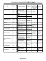
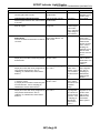
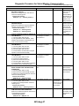
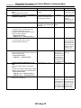
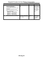
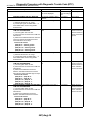
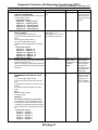
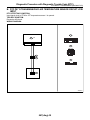
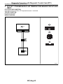
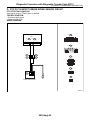
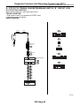
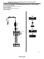
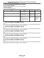
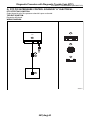
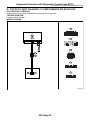
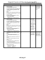
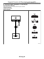
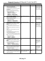
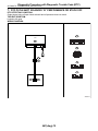
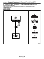
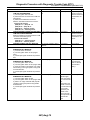
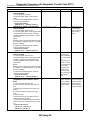
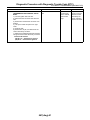
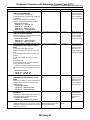
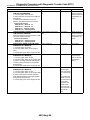
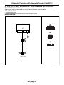
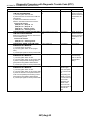
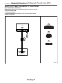
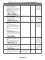
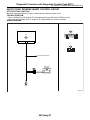
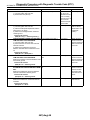
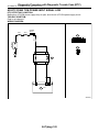
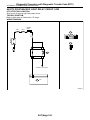
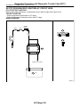
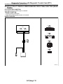
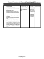
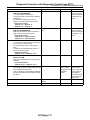
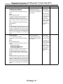
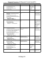
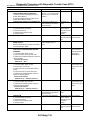
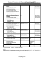
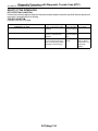
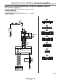
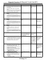
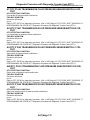
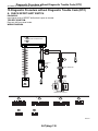
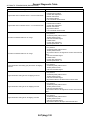
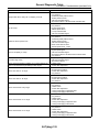
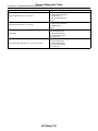
Diagnostic Procedure with Diagnostic Trouble Code (DTC)
AUTOMATIC TRANSMISSION (DIAGNOSTICS)
8
9
10
11
Step
CHECK HARNESS CONNECTOR BETWEEN
TCM AND TRANSMISSION.
Measure the resistance between TCM connector and chassis ground.
Connector & terminal
(B55) No. 4 — Chassis ground:
(B55) No. 3 — Chassis ground:
(B55) No. 14 — Chassis ground:
(B55) No. 13 — Chassis ground:
(B55) No. 20 — Chassis ground:
CHECK INPUT SIGNAL FOR TCM USING
CIRCUIT TESTER.
1) Turn the ignition switch to OFF.
2) Disconnect the transmission connector
(B12).
3) Connect the TCM connector.
4) Turn the ignition switch to ON.
5) Measure the voltage between TCM terminals.
Connector & terminal
(B55) No. 4 — (B54) No. 19:
(B55) No. 3 — (B54) No. 19:
(B55) No. 14 — (B54) No. 19:
(B55) No. 13 — (B54) No. 19:
(B55) No. 20 — (B54) No. 19:
CHECK TCM I/O SIGNAL.
Check I/O signal of power supply, ground and
PVIGN power supply relay.
<Ref. to 5AT(diag)-12, ELECTRICAL SPECIFICATION, Transmission Control Module (TCM)
I/O Signal.>
Check
Is the resistance more than 1
MΩ?
Yes
Go to step 9.
No
Repair the short
circuit in harness
between TCM connector and chassis
ground.
Is the voltage 4 — 6 V for the
inhibitor SW 1 — 4?
Is the voltage 3.5 — 5.5 V for
the inhibitor SW 3 monitor?
Go to step 11.
Go to step 10.
Is TCM I/O signal OK?
Replace the TCM.
<Ref. to 5AT-61,
Transmission Control Module
(TCM).>
Repair the open or
short circuit for
power supply and
ground. Perform
the diagnosis
according to DTC
for PVIGN power
supply relay.
Repair the open
circuit in harness
between control
valve body connector and transmission connector.
CHECK HARNESS CONNECTOR BETWEEN Is the resistance less than 1
Ω?
TRANSMISSION AND CONTROL VALVE
BODY.
1) Turn the ignition switch to OFF.
2) Disconnect the connector from transmission.
3) Remove the transmission connector from
bracket.
4) Lift-up the vehicle and place it on rigid
racks.
NOTE:
Raise all wheels off floor.
5) Drain the ATF.
CAUTION:
Do not drain the ATF until it cools down.
6) Remove the oil pan, and disconnect the
connector from control valve body connector.
7) Measure the resistance between transmission connector and control valve body connector.
Connector & terminal
(T3) No. 4 — (T5) No. 6:
(T3) No. 3 — (T5) No. 5:
(T3) No. 2 — (T5) No. 4:
(T3) No. 1 — (T5) No. 3:
(T3) No. 8 — (T5) No. 2:
5AT(diag)-37
Go to step 12.