1
Diagnostic Procedure with Diagnostic Trouble Code (DTC)
AUTOMATIC TRANSMISSION (DIAGNOSTICS)
11
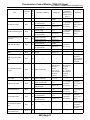
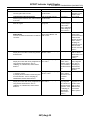
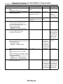
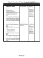
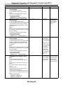
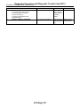
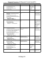
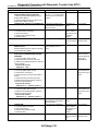
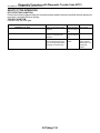
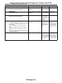
Step
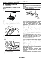
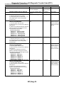
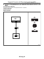
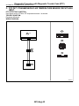
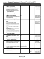
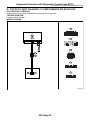
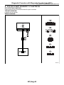
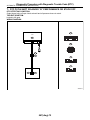
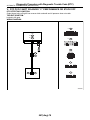
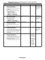
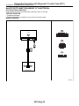
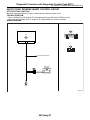
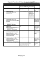
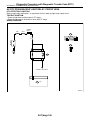
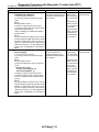
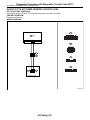
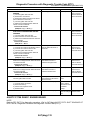
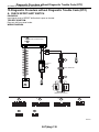
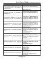
CHECK INPUT SIGNAL FOR TCM USING
CIRCUIT TESTER.
1) Connect all the connectors.
2) Lift-up the vehicle and support with rigid
racks.
NOTE:
Raise all wheels off floor.
3) Start the engine, and drive the vehicle.
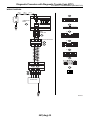
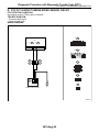
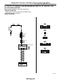
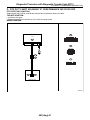
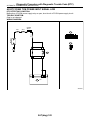
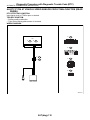
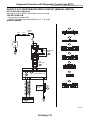
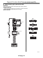
4) Measure the voltage between TCM terminals.
Connector & terminal
(B55) No. 7 (+) — (B54) No. 19 (−):
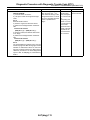
5) Stop the vehicle, and shift the select lever
to “P” range.
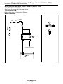
6) Measure the voltage between TCM terminals.
Connector & terminal
(B55) No. 7 (+) — (B54) No. 19 (−):
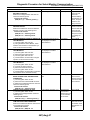
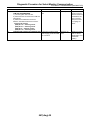
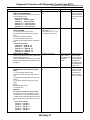
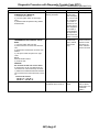
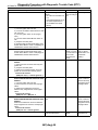
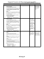
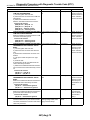
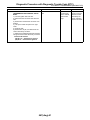
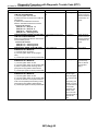
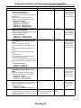
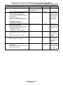
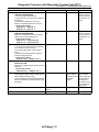
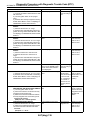
Check
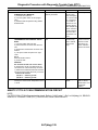
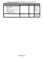
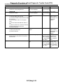
Does the voltage change
within the range of 2 — 3 V
when vehicle is driving? Is the
voltage less than 0.5 V or more
than 4.5 V constantly when the
vehicle is parked with “P”
range?
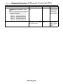
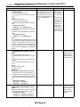
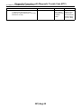
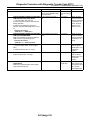
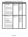
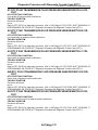
NOTE:
The speed difference between front and rear
wheels may light the ABS warning light, but this
indicates no malfunction. When AT control diagnosis is finished, perform the ABS memory
clearance procedure of on-board diagnostics
system. <Ref. to ABS(diag)-27, Clear Memory
Mode.>
5AT(diag)-113
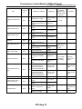
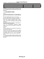
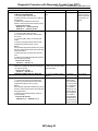
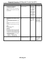
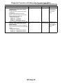
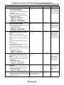
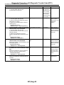
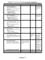
Yes
No
Even if the SPORT Replace the transindicator lights
mission harness.
blinks, the system
is in normal condition.
A temporary poor
contact of connector or harness may
be the cause.
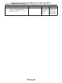
Repair harness or
contact in the ATF
temperature sensor and transmission connector.