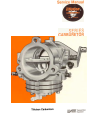
1
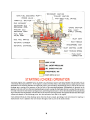
~
LL
.
-
Tillotson
Carburetors
INTRODUCTION
The Tillotson diaphragm series carburetors have been adopted as standard fuel systems on chain saw, snow vehicle, and
industrial engines throughout the world. The H D series diaphragm carburetor has been developed by the Tillotson
Manufacturing Company to make the advantages of a diaphragm carburetor available for use on larger engines having
displacements of from 20 to 40 cubic inches per cylinder. The smaller carburetor features of construction simplicity,
vibration resistance, tilt ability and easy servicing have been maintained and a more sophisticated fuel metering system
has been added.
It is available as a complete fuel system consisting of a carburetor, integral fuel pump and fuel filter for use on two stroke
cy<;:leengines, as a carburetor, integral fuel filter and optional positive action accelerating pump for use on four stroke
cycle engines, or as a carburetor for use on two or four stroke cycle engines.
The diaphragm controlled metering system allows precise fuel metering to the engine at extreme tilt angles and prevents
fuel level changes due to vibration. The important feature of this part of the carburetor operation is that the amount of
fuel going into the carburetor metering chamber is equal to the amount of fuel being used by the engine at any given time.
There is no reservoir of surplus fuel to spill out of the carburetor.
The dual venturi used in this model series multiplies the venturi pressure drop causing fine atomization of the fuel that is
delivered from the main fuel nozzle. The fuel reaches the engine as a combustible fog instead of a fluid stream. This venturi
system combined with the automatic power valve can produce increased power and fuel economy.
These special additional features have maintained the dependability and easy servicing characteristics of the smaller
Tillotson carburetors that have been in use throughout the world for several years.
The information contained in the following pages is presented as an aid to understanding the construction, operation and
servicing of the H D series carburetor .
CARBURETOR
ADJUSTMENT
The high speed and idle mixture screws have normal right hand screw threads. These adjustments are turned clockwise to
close, or lean the mixture, and counterclockwise to open, or enrichen the mixture. The starting adjustment opening for a
new unit, or a carburetor that has not been run on the engine, is one full turn open on both the high speed and idle
mixture screws.
The idle speed screw should be adjusted to open the throttle shutter a small amount. This adjustment should be carefully
made on vehicles that have a centrifugal clutch drive arrangement; a very high idle speed may cause the clutch to engage
and the vehicle may start to move.
Open the fuel line shut off valve, if your engine is equipped with one, and close the choke shutter. Open the throttle about
one quarter of full travel and firmly pull the starting cord until the engine fires. Open the choke shutter far enough to allow
the engine to idle until it has warmed up enough to run continuously with the choke fully open. Do not race a cold engine.
Adjust the idle mixture screw to obtain a smooth, steady idle, and readjust the idle speed screw to obtain the idle speed
recommended by the engine manufacturer. Recheck the idle mixture adjustment at the recommended idle speed. An overrich idle mixture will cause the engine to fire unevenly and there will be smoke from the exhaust. A lean idle mixture will
usually cause backfiring.
The high speed mixture screw should be adjusted with the engine at fully open throttle and under normal full load. The
mixture should be adjusted to allow the engine to operate at highest RPM. The speed will decrease with either an over rich
mixture or lean mixture.
The above procedure need not be repeated each time the engine is started. The adjustments will remain in position and will
not require frequent readjustment.
After the carburetor has been correctly adjusted, the engine should start easily. To start a cold engine, close the choke
shutter, open the throttle about one quarter of full travel, firmly pull the starting cord until the engine starts, open the
choke far enough to allow the engine to idle until it has warmed up and can run continuously with the choke fully open.
To start a warm engine, pull the starting cord. It should not be necessary to use the choke unless the engine is overheated
and fuel vapor is present in the fuel lines.
.DO NOT FORCE
MIXTURE
SCREWS
INTO THEIR
(If the engine fails to start, see the Trouble
SEATS!
Data Section.
SECONDARY
MAIN
FUEL
DISCHARGE
POWER
THROTTLE
IDLE
AIR
PORT
VENTURI
PRIMARY
VALVE~
.HIGH
VENTURI
SPEED
FUEL
BLEED
SECONDARY
DISCHA RGE
IDLE
PORT
CHOKE
PRIMARY
IDLE
DISCHARGE
PORT
FUEL
PULSE
IDLE
ORIFICE
SHUTTER
SHUTTER
FUEL
INLET
SUPPLY CHANNEL
PUMP
PORT
FUEL
METERING
METERING
:NLET
ORIFICE
INLET
CHAMBER
ATMOSPHERIC
DIAPHRAGM
SEAT
NEEDLE
VENT
INLET
CONTROL
LEVER
INLET
TENSION
SPRING
FUEL
INLET
CONNECTION
SUPPL y FUEL
FUEL
UNDER
PRESSURE
FUEL UNDER VACUUM
ATMOSPHERIC
AIR
Starting an engine that is equipped with the model HO carburetor involves the same methods that are used with the
conventional float type carburetor. As the engine is cranked with the choke in the closed position, engine suction will be
transmitted to the metering chamber through both primary and secondary idle discharge ports as well as the main fuel
discharge port, creating a low pressure on the fuel side of the metering diaphragm. Atmospheric air pressure on the
opposite or dry side will force the metering diaphragm upward causing the diaphragm button to contact the inlet control
lever and overcome the inlet tension spring pressure, permitting fuel pressure to force the inlet needle off its seat allowing
fuel to enter the metering chamber. The fuel then travels from the metering chamber through the idle and main fuel supply
orifices and channels to the discharge ports, into the carburetor bore and to the engine.
Fuel is delivered from all of the discharge ports when the choke is closed, providing a full, rich mixture for starting. A
small amount of air is added to the rich mixture through a hole or port in the choke shutter .
3
SUPPL y FUEL
FUEL UNDER PRESSURE
FUEL UNDER VACUUM
ATMOSPHERIC
AIR
PUMP IMPULSE AIR
IDLING
OPERATION
The throttle shutter is slightly open when the engine is idling. Engine suction is transmitted
to the metering chamber
through the primary idle discharge port and the idle fuel orifice. As in the starting operation, the metering diaphragm is
forced upward by atmospheric
pressure, depressing the inlet control lever , permitting
fuel pressure to force the inlet
needle off its seat, allowing fuel to enter the metering chamber. The fuel travels through the idle fuel orifice and is delivered
to the engine through the primary idle discharge port. Air from the idle air bleed and secondary idle discharge port is
mixed with the fuel before it is delivered from the primary discharge port.
The entire carburetor
bore from the air inlet to the
ball check valve in the main fuel discharge port
atmospheric pressure at the outlet of the ball check
produces the force that keeps the ball on the seat
throttle shutter is at atmospheric pressure during idle operation. The
is closed to prevent air from entering the metering chamber. The
valve and the metering chamber vacuum at the inlet of the ball check
even in an inverted position.
In all phases of operation, the amount of fuel entering
being used by the engine at any given instant.
the carburetor
4
metering
chamber
is equal to the amount
of fuel
MAIN
POWER VALVE
FUEL
DISCHARGE
IDLE AIR BLEED
PRIMARY
THROTTLE
SHUTTER
SECONDARY
IDLE
DISCHARGE
PORT
PRIMARY
DISCHARGE
IDLE
PORT
VENTURI
HIGH
SPEED
FUEL
-
ORIFICE
j""r,;'
~
\
PORT
OP~IONAL
METERING
RECI~:ULATOR
CHAMBER
,
J
INTERMEDIATE
OPERATION
Fuel is delivered into and through the carburetor
in the same manner as when the engine was idling. However, as the
throttle opens and engine speed increases, additional
fuel is required from the carburetor and is supplied to the engine
from the secondary idle discharge port which is located behind the primary idle discharge port. Air from the idle air bleed
is mixed with the fuel before it is delivered
from
the primary
and secondary
idle discharge
ports.
As the throttle shutter continues to open and the engine speed increases, the velocity of the air passing through the
primary venturi increases to create a low pressure area in the primary venturi throat. When the pressure at the main fuel
discharge port in the primary venturi is less than the pressure within the metering chamber, fuel flows through the high
speed fuel orifice
and out the main fuel discharge
port.
Fuel is also supplied to the main fuel discharge port from the power valve during intermediate speed operation. The power
valve adds fuel to the high speed fuel system for acceleration at part throttle conditions and automatically
closes at high
speeds when fuel from the high speed fuel orifice can provide adequate fuel for an economical mixture.
5
MAIN
FUEL
DISCHARGE
POWER
IDLE
AIR
THROTTLE
VENTURI
VALVE~
BLEED
HIGH SPEED
-
FUEL
ORIF ICE
SHUTTER,
SECONDARY
DISCHARGE
IDLE~
PORT
PRIMARY
PORT
IDLE
DISCHARGE
HIGH
""
SPEED
MIXTURE
SCREW
-
PORT
FUEL PUMP
PULSE PORT
FUEL
METERING
PUMP
FUEL
CHAMBER
PULSE
INLET
SUPPLY
CHAMBER
OUTLET
CHANNEL
CHECK VALVE
PUMP CHAMBER
OUTLET SURGE CHAMBER
INLET
SURGE
INLET
VALVE
DIAPHRAGM
-.//
FUEL
PUMP
DIAPHRAGM
--./
FUEL
CHAMBER~
STRAINER
INLET
CHECK
VALVE
FUEL
INLET
SCREEN
HIGH
SPEED
OPERATION
As the throttle shutter progressively opens from the intermediate position to fully open throttle, the velocity of air passing
through the primary venturi increases and fuel is metered through the high speed fuel orifice and main fuel discharge port
in sufficient quantity to satisfy the power requirement
of the engine. The power valve is closed during high speed fully
open throttle operation and the amount of fuel flowing from the main fuel discharge port is determined by the position of
high speed mixture screw.
In the operating condition of fully open throttle and low engine speed, the power valve will deliver fuel to the main fuel
discharge port to provide the rich mixture needed for this full load lugging operation. This is an operating situation such
as running a vehicle on a steep slope where the vehicle moves slowly at fully open throttle. When high speed is resumed, as
at the end of the slope, the power valve will automatically
close to maintain an economical fuel mixture.
The primary and secondary idle discharge ports deliver comparatively
little fuel at fully open throttle
used in this operating condition
is supplied from the main fuel discharge port.
FUEL
PUMP
OPERA
and most of the fuel
TION
The fuel pump is a pulse operated diaphragm pump. The pressure-vacuum
pulse is supplied from the engine crankcase
where the pulse cycles are created by the reciprocating
action of the engine piston. Crankcase pulse is transmitted to the
pump pulse chamber through the fuel pump pulse port in the mounting flange of the carburetor body. The vacuum part of
the pulse cycle causes the fuel pump diaphragm to move into the pump pulse chamber creating a vacuum in the fuel pump
chamber that allows fuel to flow from the fuel inlet through the fuel strainer screen, past the inlet check valve and into the
fuel pump chamber. The vacuum in the fuel pump chamber closes the outlet check valve during this part of the pumping
cycle.
The pressure part of the pulse cycle forces the fuel pump diaphragm into the fuel pump chamber creating a pressure on the
fuel that forces it out of the fuel pump chamber through the outlet check valve, and through the fuel inlet supply channel
to the inlet needle valve. The fuel pressure closes the inlet check valve during this part of the pumping cycle.
The inlet,and
outlet
surge chambers
diminish
the pressure surges of the fuel and provide
pump system.
6
steady fuel flow through
the
~
OPTIONAL
...for
CONFIGURA
the
HD
SECONDARY
POWER
IDLE
IDLE
AIR
MIXTURE
PRIMARY
DISCHARGE
Carburetor
r
VENTURI
I
VALVE
OPTIONAL
FUEL INLET
OR VAPOR
OUTLET
1"-FUEL
Bl-fF:D-
SCREW-
./
--
IDLE
PORT
THROTTLE
SHUTTER
OPTIONAL
;-- PRIMARY
-
--MAIN
FUEL
DISCHARGE PORT
-CHOKE
MIXTURE
--HIGH
SPEED
SCREW
ACCELERATING
PUMP
INLET
&
-
SEAT
CONTROL
INLET
\\
~
LEVER
J
L
SPRING
METERING
CHAMBER
\. ATMOSPHERIC
L
--1
TENSION
\
SPEED
FUEL ORIFICE
ACCELERATING
PUMP OUTLET
CHECK VALVE
\
-1
ACCELERATI
PUMP INLET
CHECK NG
VALVE
NEEDLE
SHUTTER
-ACCELERATING
PUMP OUTLET
--
INTERMEDIATE
VENTURI
,1
/
DISCHARGE
INLET
/
/
IDLEPORT
SECONDARY
INLET
Model
TIONS
METERING
VENT
DIAPHRAGM
J
The model H D carburetor has been designed to allow various locations for the fuel mixture adjustments. As shown in the
drawing of the accelerating pump type carburetor, the idle mixture screw, primary and secondary idle ports can be on the
top of the carburetor. The high speed orifice can be a replaceable fixed jet, and an intermediate speed mixture screw can be
added. Even with these changes the operation of the carburetor metering system and the fuel flow through the carburetor
is the same as described on the previous pages.
The accelerating pump is a positive acting plunger pump that is connected to the throttle shaft through a cam lever. When
the pump plunger is pulled to the top of its stroke during idle operation, fuel is pulled from the metering chamber past the
inlet check valve and into the accelerating pump cylinder. The plunger is moved down into the pump cylinder during
acceleration and fuel is pushed through the accelerating pump channels, past the outlet check valve and discharged into
the air stream through the accelerating pump outlet.
SECONDARY
MAIN
FUEL
VENTURI-
DISCHARGE
POWER
OPTIONAL
FUEL INLET
OR VAPOR OUTLET
i
PORT,
VALVE
~
FUEL
\
STRAINER
FUEL
PRIMARY
IDLE DISCHARGE
PORT
IDLE
PORT
THROTTLE
SHUTTER
IDLE
MIXTURE
INLEl'
PRIMARY
r--
SECONDARY
DISCHARGE
HIGH
MIXTURE
INLET
SCREW --i
I
METERING
CHAMBER
METFRING
DIAPHRAGM
7
-INLET
--I'
\
COVERj
\
L
METERING
LATMOsPHERIC
SCREEN
VENTURI
SPEED
SCREW
SEAT
NEEDLE
DIAPHRAGM
VENT
The model HO carburetor is also available with a plain diaphragm cover plate. The fuel must come from a separate fuel
pump or an overhead fuel tank for a gravity fuel supply for these two optional models.
7
~
1A Primary Idle
Discharge Port
1 B Secondary
Idle
Discharge Port
2 Throttle Shutter
3 Idle Air Bleed
4 Power Valve
5 Main Fuel Check
6 Main Fuel
HD
Valve
7A
7B
8
9
10
11
12
13
14
Discharge Port
Secondary Venturi
Primary Venturi
High Speed Fuel Orifice
Carburetor
Body
Choke Shutter
Inlet Seat Gasket
Inlet Seat
Inlet Needle
Fuel Inlet Supply
15
16
17
Channel
Fulcrum Pin
Inlet Control Lever
High Speed
18
19
Mixture Screw
Atmospheric
Vent
Metering Diaphragm
20
Cover
Atmospheric
SERIES
@-.~~
(j)-&
'J'@'
~~
CARBURETOR
21 PumpBody
~cp
23
24
25
26
27
28
29
30
~~,ft)!:2
/(j5)
"::@
/
~
@,--:->-
~
~
~~
@
--@
-@)
~
~/
-"@
1/
""@
.~h
Outlet Surge Chamber
Pump Inlet Check Valve
Fuel Pump Chamber
Fuel Inlet
Strainer Cover Gasket
Fuel Strainer Screen
Strainer Cover
Strainer Cover
Retaining Screw
31A Pump Inlet Valve
318
32
33
34
35
36
37
38
39
40
41
42
Diaphragm
Pump Diaphragm
Inlet Surge Chamber
Fuel Pump Cover
Pump Pulse Chamber
Metering Diaphragm
Fuel Pump Gaskets
Metering Chamber
Inlet Tension Spring
Metering Diaphragm
Gasket
Idle Mixture Screw
Fuel Pump Pulse Port
Idle Fuel Orifice
Chamber
HOW TO DISASSEMBLE
FOR CLEANING
AND
REPAIR
The model HO carburetor should be cleaned and inspected at regular intervals, depending on service
conditions.
2. The fuel inlet and filter cover are removed by removing the center screw. Remove the filter cover,
the cover gasket and the filter screen. The filter
screen should be cleaned by flushing with fuel or
solvent and blowing with compressed air. It is advisable to replace the gasket whenever the filter
screen is serviced. Flush all dirt from the plastic
cover before assembly.
Select a clean work area because dirt and carelessness
are the causes of most carburetor trouble.
3. Remove six body screws and the fuel pump cover
casting. Inspect the casting for nicks, dents, or
cracks that might interfere with operation. Remove
the fuel pump inlet valve diaphragm and gasket.
Inspect the diaphragm; it must be flat and free
from holes. The gasket should be replaced if there
are holes or creases on its sealing surface. Be certain to reassemble these parts in the correct
order. The pump gasket should be assembled onto
the pump body first, then the fuel pump inlet valve
diaphragm should be assembled next to the gasket
so that the flap valves will seat against the fuel
pump cover .
The entire carburetor should be cleaned by flushing with
fuel and blown dry with compressed air before disassembly. The carburetor should be inspected for
cracks in the casting, bent or broken shafts, loose levers
or swivels and stripped threads.
4. Remove the pump body casting, the pump diaphragm, and gasket. Inspect the diaphragm; it must
be flat and free from holes. The gasket should be
I. Remove the idle speed screw, washer and tension
spring. Inspect for damaged threads.
8
replaced if there are holes or creases on its sealing
surface. Inspect the pump body casting for nicks,
dents, or cracks that might interfere with operation.
Be certain to reassemble these parts in the correct
order. The pump gasket should be assembled
onto the metering diaphrag(ll cover first, then the
pump diaphragm should be assembled next to the
gasket so that the outlet flap valves will seat against
the pump body casting.
you may strip the threads or distort the--wert.
Use
a torque wrench to apply 40 to 50 inch-pounds
torque. The needle and seat assembly must be clean
to insure correct performance.
INLET CONTROL LEVER.
SET FLUSH
W I T H CHAMBER FLOOR I
5. Remove the metering diaphragm cover casting, the
metering diaphragm and gasket. Inspect the cover
casting for nicks, dents, or cracks that might interfere with operation. Inspect the metering diaphragm; the center plate must be riveted securely
to the diaphragm and the diaphragm should be free
from holes and imperfections. The gasket should
be replaced if there are holes or creases on its sealing surface. These parts must be reassembled in
the correct order. The gasket should be assembled
onto the carburetor body casting first, then the metering diaphragm is assembled next to the gasket.
HIGH SPEED MIXTURE
SCREW
METERING
CHAMBER
FLOOR
IDLE MIXTURE
9. Remove and inspect the points of the high speed
and idle mixture screws. Through misuse, either
mixture screw point may be bent, extruded from
being forced into the casting seat or possibly broken
off in the casting. If either mixture screw is damaged, be sure to inspect the condition of the casting.
If the adjustment seats are damaged, a new body
casting is required.
6. Remove the fulcrum pin retaining screw, the fulcrum pin, inlet control lever and the inlet tension
spring. Use caution in removing these parts because
the spring pressure may cause the inlet lever to
fly out of the casting. Inspect the parts for wear or
damage. The inlet control lever must rotate freely
on the fulcrum pin.
10. The idle bypass ports and main nozzle ball check
valve are sealed from the metering chamber by
welch plugs. It is seldom necessary to remove
either of these plugs because there is no wear in
either section, and any dirt that may accumulate
can usually be blown out with compressed air
through the mixture screw holes. If the carburetor
is unusually dirty and the welch plugs must be removed, it will require careful work. Drill through
the welch plug, using an 1/8 inch drill. Allow the
drill to just break through the welch plug. If the
drill travels too deep into the cavity, the casting
or the main nozzle ball check valve may be ruined.
Pry the welch plug out of its seat, using a small
punch.
7. Handle the inlet spring carefully. Do not stretch
this spring or in any way change its compression
characteristics; If in doubt about its condition, replace it.
8. Remove the inlet needle. Remove the inlet seat assembly using a 3/ 8-inch thin wall socket wrench.
Remove the inlet seat gasket.
The inlet seat assembly consists of a brass cage and
a rubber insert for the inlet needle seat. The insert
goes into the cage only one correct way. Looking
at the insert, one side is flat and smooth; the other
side has a ridge or rim molded around the outside
edge. This ridge is to be assembled away from the
inlet needle point.
Inspect the idle bypass holes to insure they are not
plugged. Do not push drills or wires into the metering holes. This may alter carburetor performance.
Blow plugged holes clean with compressed air. Remove the main nozzle ball check assembly by pressing it out of the casting into the primary venturi.
If a new part is required, press the new assembly
into the nozzle well so that the bottom surface of
the ball cage is flush with the surface of the nozzle
well. This is important because the nozzle pipe
must be below the welch plug in order to receive an
adequate supply of fuel. If this check ball is defective, the engine will not idle unless the high speed
mixture screw is shut off. Replace the defective
part.
Some models of the HD carburetor are equipped
with a rubber tipped needle, a brass inlet seat and
a copper gasket. The installation instructions below
are applicable to both types of inlet seats.
The inlet needles and seats are matched and tested
for leaks at the factory and the parts should not be
interchanged-they
must be kept in matched se~s.
When installing the insert cage into the carburetor
body, use a new gasket. Do not force the cage, as
9
II
The choke and throttle shafts may be removed if
there is evidence of wear on these parts. The shafts
do not have to be removed before cleaning the body
casting if the parts are not worn.
end punch. If the installed welch plug is concave, it may be loose and cause an uncontrolled
fuel leak. The correctly installed welch plug is
flat.
D.
Mark the throttle and choke shutters before removing them so that they can be reassembled correctly.
The edges are tapered for exact fit into the carburetor bores. Remove two screws and pull the
shutter out of the carburetor body. Remove the
throttle shaft clip and pull the shaft out of the casting. Examine the shaft and the body bearings for
wear. If the shaft shows excessive wear, replace it.
If the body bearing areas are worn, replace the body
casting. Remove the choke shaft from the body
carefully so that the friction ball and spring will not
fly out of the casting. Inspect the shaft and bushings.
REPLACE
ALL
WORN
PARTS
and cast-
E. Assemble the throttle shaft into the carburetor
body and attach the throttle shaft clip before
assembling the throttle shutter. With the shaft
secured in place, assemble the shutter into
the shaft. Make certain that the shutter fits
accurately into the throttle bore in the closed
position.
F. Assemble the spring and ball into the choke
shaft hole and assemble the shaft into position.
Assemble the shutter into the choke shaft. Make
certain that the choke shutter fits tightly to the
carburetor bore in the closed position.
12. Clean all parts before reassembling the carburetor.
The metal parts can be cleaned in a good grade of
commercial carburetor solvent. If the carburetor
is not very dirty, it can be cleaned by blowing the
parts with compressed air and carefully blowing
out each channel and orifice in the castings.
I
Assemble the gaskets, diaphragms
ings in the correct order .
14. A carefully rebuilt HD model carburetor should perform well. The two most likely causes of carburetor
failure are dirt and a careless repair job. A clean,
carefully assembled unit should be nearly as good
as new.
I
13. Assemble the carburetor. Make certain that all
parts are kept clean before they are assembled to
the body casting. Few measurements are required
to complete the assembly of this simple unit:
A.
Tighten the inlet seat to 40-50 inch-pounds
of
torque.
B. Adjust the inlet control lever so that the center
of the lever that contacts the metering diaphragm is flush to the metering chamber wall
as shown in the drawings.
c.
DEPRESS
Install new welch plugs at the nozzle well and
bypass chamber if the original parts were damaged or removed. Place the new welch plug
into the casting counter bore convex side up and
flatten it to a tight fit, using a 5/ 16 inch flat
SEE F-OLLOWING
PAGES
PRY
FOR OPERATIONAL
10
TROUBLE
AND
HERE
UP HEREI
REMEDY
DATA
TROUBLE
~
SHOOTING
The following symptoms and possible causes with corrective
guide in servicing the Model HO carburetor .
A
Idle
Lean
too lean.
channels.
missing or not tightly
valve not sealing.
sealed.
e.
B
Inlet control lever set too far away from
diaphragm.
Idle Operation Too Rich
a. Carburetor flooding.
b. Idle adjustment screw point damaged.
c. Idle air bleed plugged.
d. Idle adjustment
hole damaged, forced, oversize or casting cracked near the adjustment
point.
Intermediate System
1. Lean Operation At Intermediate Speeds
a. Adjustment set too lean.
b. Dirt in intermediate
fuel ports or
channels.
c. Channel plugs missing or not tightly
d. Main fuel check valve not sealing.
e.
2
supply
sealed.
Power valve ball stuck closed.
f.
Inlet control lever incorrectly set.
Rich Operation At Intermediate Speeds
a. Adjustment set too rich.
b. Carburetor flooding.
c. Main fuel check valve welch plug not tightly
sealed.
d. Choke valve partially closed.
e
c.
Inlet control
lever incorrectly
set.
Main Nozzle System
1. Lean Operation At High Speeds
a. Adjustment set too lean.
b. Dirt in nozzle system.
c. Adjustment packing damage.
d. Main fuel check valve damaged.
e. Main fuel check valve not seated correctly
body casting.
f. Inlet control lever incorrectly set.
2
can be used as a
System
Idle Operation Too
a. Adjustment set
b. Dirt in idle fuel
c. Channel plugs
d. Main fuel check
2
service recommendations
Rich Operation At High Speeds
a. Adjustment set too rich.
b. Carburetor flooding.
c. Power valve ball check not seatingc
d,
Inlet
control
lever
incorrectly
in
Readjust.
Blowout
with compressed air.
Reseat or replace channel plugs.
Blowout
with compressed
air or replace.
Reset control lever flush with metering
chamber wall.
See item
Replace
Blowout
Replace
E.
the adjustment screw.
with compressed air.
carburetor.
Readjust.
Blowout
with compressed
Reseat or replace channel plugs.
Blowout
with compressed
air or replace.
Remove welch plug and steel ball and
blowout
channel with compressed air.
Readjust inlet control lever.
Readjust.
See item E.
Reseat or replace.
See that choke friction spring and ball
3re correctly assembled.
Readjust inlet control lever flush with
metering chamber wall.
Readjust.
Blowout
channels with compressed air.
Replace packing.
Replace.
Reseat the assembly flush with nozzle
well surface.
Readjust inlet control lever flush with
metering chamber wall.
Readjust.
See item
Remove
blowout
Readjust
metering
set.
11
air.
E.
welch plug and steel ball and
channel with compressed air.
inlet control lever flush with
chamber wall.