1
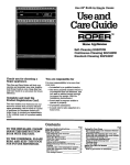
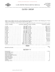
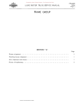
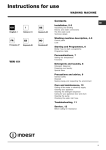
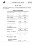
Donated by John & Susan Hansen - For Personal Use Only L-LlNE MOTOR TRUCK SERVICE MANUAL INSTRUMENTS Index Page 1 INSTRUMENT GROUP SECTION "A" Page Eq uipment for checking gauges • • • • • • • • . • • • . • . • . • . • • • • • • • • • . • . • • • • • . • • 3 Flexible shaft (tachometer) • . • • . • • . 4 Fuel gauge operation • . • . . . • . • . • . 1,2 1 General description ••••. 3,4 Method of checldng gauges Oil pressure gauge operation. 2 Service instructions • . . • . . • 1 Speedometer (and odometer) • • . • . • . • . 4 Tachometer (repairing and lubricating) • 4 Water temperature gauge operation ••• 2,3 SECTION orB" Speedometer adapter calculations .•.•••••••.•.•.•.•••••..••••••••.•••• PRINTEO IN UNITEO STATES OF AMERICA 1 Donated by John & Susan Hansen - For Personal Use Only Donated by John & Susan Hansen - For Personal Use Only R-LINE MOTOR TRUCK SERVICE INSTRUMENTS Section A Page 1 INSTRUMENTS COMBINATION STARTING AND IGNITION SWITCH R-ll0 to RF-210 (Delo-Remy No. 111650l) When the switch key is turned to the left. all accessories and gauges are "ON" except the ignition which is "OFF".. When the switch key is turned half way to the right, the accessories and ignition are both" ON". Turning the ignition switch key to the extreme right will engage the starting switch and complete the electrical circuit between the battery and the starting motor so that the pinion engages the flywheel ring gear and cranks the engine. ers 12-MARCH 1953 (Supplemental page. for erS-ll). PRfNTED IN UNITED STATES OF AMERICA, Donated by John & Susan Hansen - For Personal Use Only Donated by John & Susan Hansen - For Personal Use Only L-UNE MOTOR TRUCK SERVICE MANUAL INSTRUMENTS Section A Page 1 INSTRUMENTS Tachometer Fuel Ammeter Speedometer Air Tachometer Ammeter Speedometer Temperature gauge Oil pressure gauge Air pressure gauge Beam indicator light Temperature gauge A.22497 Fig. General Description Fig. 1 illustrates location of instruments on dash panel. Fig. 2. illustrates the rear view of the same instruments and panel assembly as in Fig. 1. The fuel gauge, oil pressure gauge, and water temperature gauge are electricallyoper ated and consist of a sender and receiver (dash) unit. Diagrams (Figs. 3 to 9 inclusive) illustrate the major parts of each unit and the principle of operation. An optional source of supply of instruments is established at the factory and the new truck may be equipped with instruments that corne to rest in the upper range when the switch is turned to "OFF" position. In these in stances. the details of operation of the unit are similar. The illustrations will apply in either case except for direction of travel after switch is turned to "OFF" position. Service Instructions. The following units require no adjustment or maintenance other than keeping the elec trical connections tight. Due to the intricate construction no attempt should be made to re pair or calibrate these units. IF UNIT FAIL URE OCCURS, REPLACE WITH A NEW UNIT. However. no unit should be removed until a thorough check has been made of wiring, sender units, condenser, etc. for a short, otherwise, a new unit will also burn out. Coil Ammeter Starter switch Ignition switch Circuit breaker Stop light switch PFUNTEC IN UNITt:O 'TATES 0,.. AMEI'HCA Oil pressure gauge A.22498 Fig. 2 Electrical tachometer Magnetic starting switch Headlight sealed beam unit Headlight dimmer switch Fuel gauge and fuel tank sender unit Oil pressure gauge and engine sender unit Water temperature gauge and engine send er unit CAUTION: Always have ignition switch in "OFF" position when changing or working on instruments to avoid the possibility of a short circuit, which will damage instruments. Both sender and receiver units must be of same type. Do not use a sender unit of one manu facturer with a receiver unit of another, or vice versa. Fuel Gauge Operation (King-Seeley) When fuel tank is empty (Fig. 3) the two contacts infuel tank sender unit are just touch ing. With the ignition switch on, current flows through the circuit, warming up the heater wires which causes the bi-metals to bend, and Operation with tank empty Tank sender A-22943 Fig. 3 - Gas Gauge - Tank Empty. Donated by John & Susan Hansen - For Personal Use Only INSTRU MENTS Section A Page 2 L-LINE MOTOR TRUCK SERVICE MANUAL bending of bi-:metal in tank sender unit opens the contacts and circuit is broken--the heater wire then cools and the bi-:metal returns to its for:mer position. Contact is then again :made and the procedure is repeated at the rate of approxi:mately once per second. Operation with low oil pressure Bimetal I~~~~~~" U ~ Grounded c o n t i d Since both heater wires are in the sa:me circuit, a si:milar slight bending of the bi-:metal in the dash receiver unit occurs, which is just sufficient to :make the needle register zero. It When tank is filled with gasoline (Fig. 4) the action of the float and Canl pushes the grounded contact against the insulated bi-:metal contact, bending the bi-:metal in the tank sender unit. Pressure Operation with tank full Insulated contad t'------' Flexible diaphragm 0 Oil pressure S plug Ignition switch Dash receiver I III ~ A-23ITS Fig. 5 - Oi I Pressure Gauge - No Pressure. Operation with high oil pressure II:~~~~~~Insulated contact Grounded contact Cam Float Flexible diaphragm Oil pressure plug Tank sender IIII~ A·22945 A-2294T Fig. q - Gas Gauge - Tank Full. Fig. 6 - Oi I Pressure Gauge - With Pressure. Now if the ignition switch is on, the action de scribed in the preceding paragraphs occurs but because the bi-:metal is already under strain a :much greater a:mount of current is required to bend the bi-:metal sufficiently to break contact in this position. A si:milar greater bending of the bi-:metal in the dash receiver unit occurs and this action pulls the needle over to the full point. The :move:ment of the needle in any posi tion caused by the :make-and-break of the cir cuit is so :minute that it can not be detected. Oil Pressure Gauge Operation (King-Seeley) The operation of the oil pres sure gauge sender unit is si:milar to the fuel gauge sender unit except that instead of a ca:m, a diaphrag:m is used as a :means of :moving the grounded contact. The dash receiver units operate ex actly the sa:me. NOTE: Should the oil pressure gauge indicate pressul"e lower than nor:mal, the engine sender unit and dash unit should be checked prior to looking further for the trouble (Fig. 5). In so:me instance low oil pressure reading on the gauge can be corrected by changing the position of the engine unit. This unit is nor:mally asse:mbled with the small depression in the cover at the Note in Fig. 6 that the deflection of the diaphrag:m pushed the grounded contact agains t the insulated bi-:metal contact, bending the bi :metal in the sender unit. Water Temperature Gauge Operation (King-Seeley) The engine sender unit consists of a fixed grounded contact, so positioned that the bi :metal against which it presses is bent :mechan ically. At low te:mperatures (Fig. 7) consider able heat is required to :make this bi-:metal bend away fro:m the grounded contact. With the te:mperature of the engine-cooling water • Operation with low temperature Insulated contact Bimetal Bimetal-temperature operated .~ Heater wire Heater wire ~~ ~'; :G=ro~u=nd=e=d"\:t:=on~ a~c; -t -7\. Water temperature-heat plug A.22944 Fig. 7 - Water Temperature Gauge - Cold. Donated by John & Susan Hansen - For Personal Use Only L-UNE MOTOR TRUCK SERVICE MANUAL INSTRUMENTS Section A Page 3 Operation with high temperature Instrument being tested. 1/11f-:l.. Ignition switch V A-22946 Fig. 8 - Water Temperagure Gauge - Hot. low, all this heat must be generated electri cally, and this same current flowing through the heater wire of the dash r~ceiver creates an equal amount of heat there and a resultant bending of the dash receiver bi-metal, causing the pointer to show a low temperature reading. As the water temperature rises, its heat aids in bending the sender bi-metal--less heat is generated electrically, the resultant bending of the bi-metal in the receiver is less, result ing in higher temperature readings (Fig. 8). The following service instructions apply to fuel level, oil pressure or water tempera ture gauges. IMPORTANT: Do not disconnect instru ments with ignition switch" ON" as there is dan ger of causing a short circuit which will dam age instruments. Always turn ignition switch "OFF" before changing or working on instru ments. NOTE: If it is necessary to replace the receiver unit, because it has been burned out, then check wiring, sender unit, and condenser, if any, for a short, and correct this condition, otherwise, newreceiver unit will also burn out. A short in the gauge circuit is easily rec ognizable because it will cause receiver unit to over-read and in most cases beyond full scale. Equipment Necessary for Checking Gauges 1. One new fuel tank unit. If there is any ques tion about the new tank unit being correct, then hook it up in s'eries with a receiver unit known to be satisfactory, and apply 6 volts of current. Operate tank unit by hand and see if receiver unit reads zero with tank unit float in bottom position and full with tank unit float in top position. 2. Two ten-foot lengths of insulated wire equipped with clip terminals at each end. PRINTEO IN UNI't£P STATES OF AMnHCA A·22931 Fig. 9 - Method of checking gauges. These long lengths will in practically all instances permit individual making check to sit in seat of truck and observe gauge being checked. Method of CheCking Gauges (IMPORTANT: No units should be re moved from truck until check has been com pleted which shows such units to be damaged or defective.) 1. Disconnect sender unit being checked and hook in tank unit as shown in Fig. 9. Turn on ignition switch and operate float rod of tank unit by hand. With float of tank unit at bottom position, receiver unit being checked should register at bottom mark on dial. Next, move float rod up to top po.si tion, then receiver unit being checked should move to top mark on dial (allow one minute for receiver to corne to rest). NOTE: Exceptions to this are the oil pres sure and water temperature gauges. The oil pressure gauge should register at the RUN mark with the float rod at top posi tion. This is the mark just below the top mark on this gauge. The water tempera ture gauge should register at the HOT mark. 2. If receiver unit operates correctly, then check sender unit on truck to see if it is properly grounded. Also (a) if truck is radio-equipped check condenser on sender unit. If condenser is shorted, it will cause receiver unit to overread. When replacing condenser, it is preferable to use .one of .10 or .20 micro-farad capacity, but up to .50 can be used if necessary to cut out radio interference. (b) If ground and con denser are satisfactory. then replace sender unit and check to see if this has corrected the difficulty. 3. If receiver does not operate or fails to operate correctly then check wire lead to receiver unit. Do this by attaching one end Donated by John & Susan Hansen - For Personal Use Only INSTRUMENTS Section A Page 4 L-LINE MOTOR TRUCK SERVICE MANUAL of a ten-foot length of wire to the terminal of the receiver unit to which sender unit wire was attached. Ground the other end of the ten-foot lead and turn on the ignition switch. If the gauge operates now and did not operate with the regular wire COnnec tion, the wiring is at fault and must be re placed. If wiring is satisfactory then replace re ceiver unit and check again with tank unit. Do not attempt the repair or calibration of any receiver or s ending unit in the field as this is not practical. Replacement with a new unit is the only practical means of servicing these gauges. Speedometer The speedometers used on L-Line trucks are of the magnetic-type. A speedometer is used on a vehicle to in dicate speed in miles per hour as shown by the pointer on face dial, and to record distance traveled by means of an odometer. The speed ometer is driven through a flexible shaft con nected to a set of gears in the vehicle trans mission. These gears are designed for the particular vehicle model and take into con sideration the tire size and rear axle ratio. The flexible shaft, which connects the trans mission driven gear to the speedometer, con sists of an outer casing and inner core. The odometer usually records up to 99,999 miles before it automatically returns to zero. The extra wheel on the right side of the odom eter is known as the tenth dial, replacing the old type trip odometer, and records every tenth of a mile. There are occasions when, due to change in axle ratios or tire sizes, it is necessary to make compensating corrections in the speed ometer drive gear. For method of speedometer adapter calculations, see following Section "B", Instruments. Tachometer A tachometer is installed on a vehicle to record engine r.p.m. speeds and enables the driver to keep engine within efficient operating range. The magnetic type tachometer is installed at the factory on all Super Red Diamond En gines. It is driven by a flexible shaft connected to the vehicle distributor shaft by means of a drive joint or adapter and records the r.p.m. from the dis tributor shaft onto the face. dial through a magnetic field within the unit. There are two additional types of tachom eters available, namely, centrifugi:d, with a maximum r.p.m. hand, and electrical. The centrifugal tachometer works on the weight-type governor principle and is driven from the distributor s,haft in the same manner as the magnetic type. The centrifugal type als 0 has a maximum r.p.m. hand on the tachometer head to record maximum speed of engine. The electric tachometer is a two-unit combination consisting of transmitter and tachometer head. The head is mounted on the instrument panel and the transmitter on engine side of dash. The transmitter name plate pro vides a cover for an easily replaceable standard flash-light battery wliich supplies a fixed volt age to guarantee 2% overall accuracy. The current requirement is so small that the bat tery will give a normal service of approximately six months. The electric tachometer receives electrical impulses from the distributor through the transmitter arid records the r.p.m. in this manner. Tachometer Flexible Shaft A complete flexible shaft consists of two major assemblies. A flexible outer casing with nuts and ferrules at both ends and a wire wound flexible inner coil assembly with squared ends or crimped-on tiP'S. The core diameter and end connections vary for different applica tions. One end of the flexible shaft is attached to the instrument (speedometer or tachometer) and the other end is attached to the transmission or power take-off point. The flexible inner core transmits the power from the take-off, while the outer casing is held rigidly in place at each end by the ferrules and nuts. Repairing Tachometer Flexible Shaft Disconnect both ends of the shaft and re move from vehicle. Pull the core out of the casing and check for kinks by rolling on a flat surface. If a flat surface is not available, take an end in each hand and roll core between fin gers. In either case a core kink will show up as a "hop" at the kinked point. Never reuse a kinked core, because it will cause fluctuation of the speedometer or tachometer point. Also check for frayed spots by running it loosely through your finger. Do not reuse a frayed core. Kinked or frayed core usually indicates a casing with very sharp bend. CAUTION: Under no circumstances should a casing have less than a six-inch radius bend. Lubricating Tachometer Flexible Shaft Thoroughly clean the core and cas ing. Ap ply a thin coat of graphite impregnated non hardening grease evenly over the core ONLY. Hold the casing with one hand and feed the core with lubricant into casing. CAUTION: Never fill or pack the casing with grease. Periodical lubrication of the flexible shaft is recommended to avoid premature failure. Donated by John & Susan Hansen - For Personal Use Only INSTRUMENTS Section B Page 1 L·LINE MOTOR TRUCK SERVICE MANUAL METHOD OF SPEEDOMETER ADAPTER CALCULATION There are occasions when. due to changes in axle ratios, or tire size. it is necessary to make compensating corrections in the speedometer drive. . Parts catalogs list available speedometer adapters and the one chosen should most closely coincide with the calculated results. The following formulae are based on new tire radii when correctly inflated and properly loaded, and should prove helpful in selecting speedometer adapter equipment. Problem Formulae Problem Formulae (A) Actual distance (D) Old tire rev. per mile *Present Required Err.or in traveled *Present Required Tire size X adapter adapter speed X adapter = adapter has been ratio ratio. ometer Speedometer ratio ratio. changed. New tire rev. per mile reading indication NOTE: If no adapter in present hook *NOTE: If no.adapter in present hook up - disregard in calculations. up - disregard in calculations. EXAMPLE: Old tire rev. per mile (7.00-20): 573 New tire rev. per mile (9.00-20): 525 EXAMPLE: Actual distance traveled: 5 miles *Present adapter ratio: 1.155 6 miles Speedometer reading: Formula is then: Required *Present adapter ratio: 1.200 573 X *1.155 = 1.260 adapter Formula is then: ratio. Required adapter Ir----(E--)---+*-p--r-e-s-e-n-t--a-d-a-p-t-e-r--r-a-t-io--X----------- X *1.200 = .9996 ratio. Required --------/------------------------------------11 Ti re s iz e old ti re rev. per mile X and axle old axle ratio adapter (B) Old axle ratio *Present Required ratio b o t h . . ratio. -----------. X adapter Axle adapter h d New tlre rev. per mlle X New axle raho ratio new axle ratio c ange . ratio ratio. has been NOTE: If no adapter i n present hook changed. *NOTE: If no adapter in present hook up - disregard in calculations. up - disregard in calculations. EXAMPLE; = i EXAMPLE: Old axle ratio: New axle ratio: *Present adapter ratio: Formula is then: 5.285 X *1.155 = .9909 6.16 5.285-1 6.16-1 1.155 Required adapter ratio. (c) 10084 To find *Tire rev. (F) Loaded tire radius tire -per mile. To check in inches revoluadapter Hons if ti re per mile. *Deduct 1'10 for high pressure tires, diameter, or 1-1/2'10 for balloon tires. axle ratio, and NOTE: See CT-350 for tire radius speedspecifications. ometer drive and EXAMPLE: driven Constant figure: 10084 gears are Loaded tire radius of 7.50-20 tire: known. Formula is then: 10084 - - - = 582 17.3 Tire rev. 582 - 1-112'10 = 573 per mile. PRINTED IN UNITED STATES OF AMERICA *Present adapter ratio: 1.155 Old tire rev. per mile (7.00-20): 573 Old axle ratio: 5.285 New tire rev. pe r mile (9.00-20): 525 New axle ratio; 6.16-1 Formula is then; 1.081 1.155 X 573 X 5, 285 = Required adapter 525 X 6.16 ratio. * Loaded tire radius X 0.1 X numberteethindrivengear _ Adapter Axle ratio X number teeth ratio. in drive gear NOTE: See CT-350 specifications. EXAMPLE: Loaded tire radius Constant figure: Number of teeth in driven gear: Axle ratio: Number of teeth in drive gear: Formula is then: 18.9 X 0.1 X 14 6.16 x 4 for tire radius (9.00-20): 18.9 0.1 speed 14 6.16-1 speed 4 1.073 Adapter ratio. Donated by John & Susan Hansen - For Personal Use Only