1
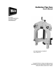
151 Lawrence Drive, Livermore, CA 94551
Phone: (925) 454-9500 Fax: (925) 454-9501
www.fabcoautomotive.com
TABLE OF CONTENTS
VI. CLEANING AND INSPECTION
I. DESCRIPTION AND OPERATION
A.
B.
C.
D.
A. Choice of Cleaning Methods
B. Drying and Corrosion Inhibition
C. Inspection
General Description
Operation
Operating Instructions
Specifications
VII.
II. LUBRICATION
General Precautions for Reassembly
Inner Drive Yoke Seal Installation
Lower Kingpin Bearing Installation
Upper Kingpin Bearing Installation
Upper Kingpin Bracket and
Kingpin Assembly
F .Steering Arm Assembly
G.. Inner Axle Shaft and
Cardan Joint Assembly
H. Spindle and Torque Plate Assembly
I . Hub Seal Installation
J. Hub, Disc Brake Rotor and
Wheel Bearing Assembly
K. Lower Kingpin Bracket and
Kingpin Assembly
L. Outer Yoke Shaft Seal Installation
M. Outer Yoke Shaft Assembly
N. Installation of Outboard Section
of Steerable Drive End
O. Disc Brake Caliper Installation
P. Final Assembly
A.
B.
C.
D.
E.
A. Wheel Bearings
B. Cardan Joints
C. Kingpin Bearings
D. Differential Carrier
E. Steering and Tie Rod Ball Joints
Ill. AXLE ADJUSTMENT
A.
B.
C.
D.
E.
F.
G.
Wheel Bearing Adjustment
Kingpin Adjustment
Steering Stop Adjustment
Camber Adjustment
Caster Adjustment
Toe-In Adjustment
Cardan Joint Adjustment
IV. WHEEL BEARING SERVICE
A. Hub and Wheel Bearing Disassembly
B. Wheel Bearing and Hub Assembly
V.
STEERABLE DRIVE END DISASSEMBLY
A.
B.
C.
D.
STEERABLE DRIVE END ASSEMBLY
General Precautions for Disassembly
Preparation for Disassembly
Disc Brake Caliper Removal
Removal of Outboard Section
of Steerable Drive End
E. Outer Yoke Shaft Disassembly
F. Outer Yoke Shaft Seal Removal
G. Lower Kingpin Bracket and
Kingpin Disassembly
H. Hub, Disc Brake Rotor and
Wheel Bearing Disassembly
I . Hub Seal Removal
J. Spindle and Torque Plate
Disassembly
K. Inner Axle Shaft and
Cardan Joint Disassembly
L. Steering Arm Disassembly
M. Upper Kingpin Bracket and
Kingpin Disassembly
N. Upper Kingpin Bearing Removal
O. Lower Kingpin Bearing Removal
P. Inner Drive Yoke Seal Removal
VIII.
DIFFERENTIAL CARRIER REMOVAL AND
INSTALLATION
A. Removal of Differential
Carrier from Axle Housing
B. Installation of Differential
Carrier into Axle Housing
IX. DISC BRAKE SERVICE
A. Brake Shoe Replacement
B. Caliper Overhaul
X. TORQUE SPECIFICATIONS
Xl. TOOL REFERENCE
PARTS MANUAL
Page 27 through 31
ADDITIONAL SERVICE MANUALS
Single Reduction Differential Service Manual
Double Reduction Differential Service Manual
Drive Thru Style Differential Service Manual
625 330B
Copyright © 1987 by Fabco, Inc.
I. DESCRIPTION & OPERATION
Model SDA 23
Steerable Drive Axle
A. General Description
The SDA 23 front drive axle is nominally rated at a static load capacity of 23,000 pounds. The axle consists of four
major assemblies. These assemblies are the axle housing, two steerable drive ends, and the differential carrier.
B. Operation
Driving forces are put into the axle at the pinion yoke on the differential carrier; they pass through the differential to
the inner axle shafts and the inner drive yoke of the cardan joint; they then pass into the outer yoke shaft which
connects to the wheel hub and rotates the wheel.
When steered, the outer section of each steerable drive end turns about the kingpin centerline. The cardan joint,
centered on the kingpin centerline, allows driving forces to turn with the steered wheel ends.
The axle is equipped with single free-floating caliper disc brakes, which are hydraulically actuated.
C. Operating Instructions
In conditions where the vehicle rear wheels might spin, such as sand, loose dirt, mud, snow, ice or ascending
grades, the front drive axle can be shifted into operation for improved traction. Engagement can be made at any
vehicle speed, unless the rear wheels are spinning. Engagement is best accomplished while the engine is pulling
lightly.
—2—
D. Specifications
• Maximum capacity
• Brakes—
Type
Size
Certified
23,000 pounds load capacity
Disc, single free-floating
caliper, hydraulically actuated
15% in. diameter rotor
FMVSS 121
• Housing
Fabricated, cast steel banjo and tubes
• Spring Centers
Minimum 32 inches
• Spring Width
To 4 inches
• Caster
To customer specifications
• Camber
Adjustable
• Wheels—
Mounting
Minimum Wheel Size
10 studs on 13
133/ls in. circle
22.5 inches
• Differential Carrier
Ring Gear
Spiral bevel, 18 in. diameter
• Single Reduction Ratios
3.70, 3.90, 4.11, 4.33, 4.56, 4.88, 5.43, 6.17, 6.67
• Double Reduction Ratios
5.04, 5.60, 5.90, 6.21, 6.64, 7,39, 8.40, 9.08
• Hi-Entry Ratios
6.05, 6.74, 7.08, 7.45, 7.97, 8.87, 10.08
• Steering arm
To Customer specifications
• Cardan Joint
10c
• Kingpins—
Type
Inclination
• Track
Spherical, in Nylatron races, patented Fabco design
8°
-i n. over wheel mounting faces
Std. 91
91%in.
• Axle Shafts—
Spline
Body
-i n.diameter, 24 splines
2%in.
2%in.
-i n. diameter
• Turn angle
35°
• Weight
1990 Ibs. (dry)
• Lubrication —
Axle Housing
Capacity
17 qts.
• Options
Dual Steering arms
—3—
Wider Track
II. LUBRICATION
Recommended Lubricants
LUBRICANT
ABOVE 32°
BELOW 32°
Gear Oil
MIL-L-2105 B
SAE 140
MIL-L-2105 B
SAE 90
Chassis Grease
MIL-G-10294
MIL-G-10294
Wheel Bearing
Grease
NLGI Grade #2
NLGI Grade #2
A. Wheel Bearings
Wheel bearings require cleaning, inspection, and oil
change at every brake shoe and lining replacement.
Wheel bearings should be lubricated in accordance
with the vehicle manufacturer’s recommendations.
The wheel bearings may either be oil lubricated or
packed with grease. Grease packed lubrication combined with oil lubrication may also be used.
1. Greased Packed Wheel Bearings
a. Refer to Section IV, “Wheel Bearing Service”
and follow part A.
b. Pack the wheel bearings with wheel bearing
grease and refer back to Section IV, and follow
part B.
2. Oil Lubricated Bearings
a. Cleaning:
If bearings are to be cleaned, refer to Section
IV, “Wheel Bearing Service” and follow part A.
After cleaning, lightly oil bearings and assemble
bearings by referring back to Section IV and following part B.
b. Draining:
Draining oil filled wheel hubs is best accomplished after the vehicle has been operated
briefly, allowing the oil to become warm and
flow freely. Remove the aluminum hub cap.
Fig. 3 Grease Fitting Points of Axle End
—5—
Drain the hub by removing one bolt from the
hub cap (located on the drive flange) and rotating the hub until the open threaded hole is at its
lowest position.
c. Filling:
Rotate the wheel hub until the open threaded
hole is on the horizontal centerline of the axle.
Fill the hub with lubricant, level with the
threaded hole (see fig. 4), and assemble the
bolt to the hub cap. Reinstall the aluminum hub
cap. The lubricant should be the same as the
lubricant used in the differential carrier. See the
recommended lubricant chart for choice of
proper lubricant.
B. Cardan Joint
The cardan joints should be lubricated at each
chassis lubrication (approximately 1000 mile intervals). Vehicles operating with the cardan joints submerged should have the joints lubricated at more
frequent intervals. A low pressure grease gun containing chassis lubricant or gear oil should be connected
to the lube fitting on the cardan joint and pressure ap-
plied until seepage is detected around each of the
rubber cap seals. If all seals do not release lubricant,
move the bearing cross laterally in all four directions,
then pull down on the bearing cap opposite the side
that did not release. Apply lubricant pressure until a
flow of lubricant appears.
C. Kingpin Bearings
The kingpin bearings require lubrication at each
chassis lubrication (approximately 1000 mile intervals). To ensure thorough lubrication, the front axle
should be raised slightly to relieve weight. A low pressure grease gun containing chassis lubricant should
be connected to the lube fittings on the suspension
yoke and the upper kingpin bracket and pressure applied. To ensure that old, contaminated grease is
completely forced out, pressure should be maintained
until new grease appears.
D. Differential Carrier
Differential carrier lubricant should be changed at
the same interval as the rear axle, or after each
10,000 miles of operation. Draining is best accomplished after the vehicle has been operated briefly,
allowing the oil to become warm and flow freely. Remove both drain and level plugs and allow housing to
empty completely. Clean the magnetic drain plug and
install drain plug to housing. Fill housing with gear oil
level with level plug hole. Replace level plug and
examine housing for leaks around plugs and gasket
area. See recommended lubricant chart for choice of
proper lubricant, or refer to the Differential Carrier
Service Manual supplement for detailed lubrication
specifications.
E. Steering and Tie Rod Ball Joints
Ball joints at tie rod ends and steering arms should
be lubricated every 1,000 miles with chassis lubricant.
Apply lubricant through lube fittings with a low pressure grease gun until new grease appears around the
—6—
ball stud shaft. At each lubrication the steering system
should be thoroughly inspected for loose, cracked, or
worn components. Careful attention to such details is
a vital safety factor.
Ill. AXLE ADJUSTMENT
Note: Brake service is covered in the Disc Brake
Service, Section IX.
A. Wheel Bearing Adjustment
Note: A special wrench is available for adjustment of
wheel bearing nuts. See Tool Reference, Section Xl.
1. The front of the vehicle should be raised and
properly supported. Remove the front wheels off
the axle.
2. Remove the aluminum hub cap. Remove the nut
from the end of the yoke shaft. Remove nuts
holding outer drive flange to hub.
3. Install two l/2- bolts in drive flange extractor bolt
holes and tighten bolts to remove flange from
yoke shaft spline (See fig. 9). Note: If the wheel
bearings are oil lubricated there will be a loss of
oil from inside the hub when the drive flange
is removed. Be sure to take the necessary
precautions.
2. The lower kingpin jam nut should be loose or
loosened and the lower kingpin ball stud backed
down all the way.
3. Raise the wheel hub, spindle yoke and kingpin
bracket assemblies with a hydraulic jack located
under the torque plate. On units with an upper
kingpin adjusting screw projecting through the upper kingpin cap or steering arm, adjust the screw
to raise the aforementioned parts. Raise unit until
the upward movement is resisted by the bottom
of the upper kingpin bearing coming into contact
with the lower spherical surface of the upper kingpin ball stud.
4. Put a stack of feeler gauges between the lower
kingpin bracket and the suspension yoke. The
feeler gauges should fill the gap snugly.
4. Remove wheel bearing lock nut and lock-washer
from spindle. Loosen wheel bearing adjusting nut.
5. Turn the lower kingpin ball stud upward until the
stack of feeler gauges loosen (See fig. 5).
5. Tighten wheel bearing adjusting nut while rotating
hub assembly to ensure bearings are properly
seated. Back nut off Y2 turn.
6. Back off the lower kingpin ball stud one quarter
turn (90°).
6. Tighten wheel bearing adjusting nut to 50 ft. Ibs.
torque, then back off l/4 turn.
7. Install wheel bearing lockwasher over adjusting
nut dowel with tang in keyway, moving adjusting
nut slightly if necessary. Install wheel bearing
locknut, tightening nut to 250-400 ft. Ibs. torque.
Spin hub and rotor assembly to check for tight or
loose wheel bearings.
8. Check end play using a dial indicator. End play
should be between .001” and .010”.
7. Tighten the jam nut to the correct torque while restraining the lower kingpin ball stud from turning.
On units with an upper kingpin adjusting screw,
back off the screw 11’4 turn. Restrain screw while
tightening locknut.
8. Remove the jack or hoist. Using a pry bar under the
upper kingpin bracket, l/32 to 3/32 play may be
observed on a new assembly. After loading, up to
l/8 play is acceptable. More than this requires
inspection for wear or distortion.
9. Install drive flange and gasket to hub with stud
nuts. Tighten nuts to correct torque.
10. Install the self locking nut on the end of the yoke
shaft. Tighten to correct torque.
11. Check cardan joint adjustment per Section III,
part G.
12. If the wheel bearings are oil lubricated, refill the
hub cavity with the appropriate lubricant (See
Lubrication Section II).
13. Refer to Section VII, and follow part P, “Final
Assembly.”
B. Kingpin Adjustment
1. The front of the vehicle should be raised and
properly supported. Front wheels should be off
the axle.
—7—
Fig. 5
C. Steering Stop Adjustment
1. Adjust the tie rod to give zero to one eighth inch
toe-in (See Section III, part F).
2. Steering stop adjustment is made at the factory
and normally needs no further action — unless
major parts such as the suspension yoke, spindle
yoke or kingpin brackets have been replaced.
3. The purpose of the stop is to protect the cardan
joint or any other part from hitting another part in a
full turn of the steering.
4. Turn the steering to put the axle first in the full left
turn position. The head of the stop bolt should stop
the turn before any of the rotating parts in the left
hand steerable drive end interferes with another
part. Turn the steering to the right and check the
corresponding conditions.
Note: Power steering stops in the vehicle steering
gear should not allow the application of power to the
steering when the steerable drive end is in the full
turn condition.
5. To adjust the steering stop, loosen the lock nut and
adjust the stop bolt. After adjustment, tighten lock
nut.
D. Camber Adjustment
1. Refer to section V and follow part B.
2. Adjustment is made by the addition or subtraction
of shims. Each shim will change the camber W.
3. Remove two bolts from upper kingpin bracket and
loosen two stud nuts, separating bracket from
torque plate.
4. Remove or install shims as necessary to achieve
the desired camber (See fig. 6).
5. Typical setting is l/2’ positive, accomplished by
factory installation of a shim between the upper
kingpin bracket and torque plate. Consult a tire
specialist for specific recommendations.
6. Re-install bolts. Tighten bolts and stud nuts to correct torque.
Fig. 6
E. Caster Adjustment
1. Caster is set by vehicle manufacturer and can be
adjusted only by shims between the axle spring
seat and the spring. Note: Caster change will also
change drive line angles.
F. Toe-In Adjustment
1. Jack up the front of vehicle.
2. Rotate tires and scribe a line completely around
the tires with a crayon held to the center of tire.
3. Lower jack.
4. Loosen tie rod clamp bolts.
5. Measure distance between scribed lines on front
and back of tires.
6. Turn tie rod tube with a pipe wrench to adjust
toe-in. Set tie rod length until front measurement
is 0 to l/8” less than rear measurement. If the
vehicle has a full-time front drive system (proportioning differential), alignment should be O-1/8
more in front than in rear, for toe-out. Consult tire
specialist for a specific recommendation if specialized tires are used.
7. Tighten tie rod clamp bolts to correct torque. Roll
vehicle forward at least a distance equal to four
turns of wheels and recheck toe-in. Repeat procedure if necessary to achieve final toe-in
dimension.
—8—
G. Cardan Joint Adjustment
Note: Adjustment of the cardan joint is made at
factory assembly. Cardan joint adjustment should only
be needed if three or more major components have
been replaced. Replacement of only one or two components should not alter the shim requirement. Therefore, adjustment is generally not necessary.
1 . Measure the horizontal distance between the inner
face of the outer drive yoke and the inner face of
the torque plate at the lower kingpin bracket (See
fig. 7). Distance should be 3.41” (87 mm).
4. Remove or install shims under the cap as necessary to achieve dimension noted above (See fig.
8).
Fig. 8
Fig. 7
2. With one camber adjustment shim in place (See
section III, part D), measurement in step one
should be as indicated. If additional camber adjustment shims are used, add one-half of added thickness to the normal desired dimension to arrive at
proper value for step one.
3. Adjust as follows: After removing the locknut from
the end of the yoke shaft and after removing the
bolts from the yoke shaft retaining cap. Note: If the
wheel bearings are oil lubricated, there will be a
loss of oil when the cap is removed. Be sure to
take the necessary precautions.
5. Replace the yoke shaft retaining cap with five of
the six hub cap bolts and tighten. Check the dimension to ensure proper distance. Repeat procedure if dimension is incorrect.
6. Turn hub so that remaining hole is on the horizontal center line of the axle.
7. Using a suitable low-pressure system, fill the hub
cavity with appropriate lubricant level with hole if oil
lubrication is being used (See Lubrication, Section
II and fig. 4, and page 5.)
8. Install remaining bolt and the yoke shaft retaining
locknut. Tighten to the correct torque values.
—9—
IV. WHEEL BEARING SERVICE
A. Hub and Wheel Bearing
Disassembly
1. Refer to Section V and follow part B, “Preparation
for Disassembly.”
2. Refer to Section V and follow part C, “Disc Brake
Caliper Removal” (steps 3 through 6, only).
3. Remove the aluminum hub cap.
4. Remove the yoke shaft retaining locknut from the
center of the yoke shaft retaining cap. Early
axles were equipped with a capscrew that retained the yoke shaft. (The photographs in this
manual are of an early axle.) Remove nuts holding outer drive flange to the wheel hub (see
fig. 9).
8. Install transmission jack adapter on a suitable
transmission jack (See fig. 11 and Tool Reference, Section XII). Supporting hub and rotor assembly with the transmission jack, back the hub
off the spindle, using care to avoid damage to
bearing surfaces and threads (See fig. 12).
9. Remove inner wheel bearing cone from spindle.
10. Remove hub and rotor assembly from the jack
and remove wheel bearing cups from hub if replacement is necessary.
11. Check hub seal (located in torque plate) for wear
or damage and replace if necessary.
5. Install two l/2-1 3 bolts in drive flange extractor bolt
holes and tighten bolts to remove flange from
yoke shaft spline (see fig. 9). Note: If the wheel
bearings are oil lubricated there will be a loss
of oil from inside the hub when the drive flange
is removed. Be sure to take the necessary precautions.
Fig. 10
Fig. 9
6. Remove wheel bearing nuts and lockwasher from
spindle with a Fabco wrench (See Tool Reference, Section XII and fig. 10).
7. Rock hub lightly to loosen outer wheel bearing
cone. Remove bearing cone and protect from dirt.
Fig. 11
—10—
FIG. 12
B. WHEEL BEARING AND
HUB ASSEMBLY
1. If hub seal is being replaced, apply gasket compound to outer edge of hub seal and install seal
into torque plate with a suitable tool. Lubricate inside of seal.
6. Install wheel bearing adjusting nut to spindle with
dowel facing outward.
7. Refer to Section III, part A and adjust the wheel
bearings.
2. Lubricate inner wheel bearing cone with oil or
pack with wheel bearing grease. Install wheel
bearing cone on the spindle.
8. Install drive flange and gasket to hub with stud
nuts. Tighten nuts to correct torque.
3. Install wheel bearing cups into hub in an arbor
press.
9. Check cardan joint adjustment per Section III,
part G.
4. Attach hub and rotor assembly to transmission
jack adapter (See fig. 11 and Tool Reference,
Section Xl). Raise hub to the level of the spindle
and place hub over the spindle. Use care to avoid
damage to bearing surfaces, threads, and hub
seal. Remove transmission jack from hub and
rotor assembly.
10. If the wheel bearings are oil lubricated, refill the
hub cavity with the appropriate lubricant (See
Lubrication Section II).
11. Refer to Section VII, and follow part O, "Disc
Brake Caliper Installation" and part P, "Final
Assembly."
5. Lubricate outer wheel bearing cone with oil or
pack with wheel bearing grease. Place wheel
bearing cone over spindle and into the hub.
—11—
V. STEERABLE DRIVE END DISASSEMBLY
A. General Precautions for
Disassembly
Important: Read this section before starting the disassembly procedure.
1. Follow each procedure closely in each section,
making use of both the text and pictures.
2. The outside of the unit should be carefully cleaned
before starting the disassembly. If steam cleaning,
insure that the breather and air fittings are covered
to prevent water from entering assembly.
3. Cleanliness — Provide a clean place to work. It is
important that no dirt or foreign material enters the
unit during repairs.
C. Disc Brake Caliper Removal
Brake service and steerable end disassembly requires
removal of the brake caliper assembly.
1. Follow part B, this section.
2. Refer to Section IX, “Disc Brake Service” for detailed caliper service procedures.
3. Remove about 213 of the total brake fluid from the
brake cylinder reservoir which serves the disc
brakes. Do not drain the reservoir completely. Most
service will not require removal of the hydraulic
line if care is taken to avoid letting the caliper
assembly hang by the hydraulic line.
4. Refer to the exploded views located on page 29 as
a guide to disassembly.
4. Remove the two bolts from the lower caliper holddown assembly. Remove the two bolts from the
upper caliper hold-down assembly while keeping a
firm hold on the caliper assembly.
5. Assemblies—When disassembling the various assemblies, lay all parts on a clean bench in the
same sequence as removed. This procedure will
simplify reassembly and reduce the possibility of
losing parts.
5. Lift the caliper off the torque plate and support suitably, do not hang caliper from hydraulic line. Lay
the caliper on the suspension.
6. Bearings — Carefully wash and relubricate all
bearings as removed and protectively wrap until
ready for use. Remove bearings with pullers designed for this purpose, or in manner which will not
damage those bearings that will be reused.
7. When necessary to apply a force to remove a part,
use of a puller or press would be preferred. However, sometimes it may be necessary to use a soft
hammer or bar.
B. Preparation for Disassembly
1. Raise the front of the vehicle with a jack and secure with jack stands of suitable capacity.
6. Remove the inner shoe and lining assembly from
the torque plate.
D. Removal of Outboard Section
of Steerable Drive End
1. Follow parts B and C, this section.
2. Remove the cotter pin and castle nut from each tie
rod end. Pry between the tie rod end and the tie
rod arm and at the same time, strike the side of the
tie rod end tapered stud. Remove the tie rod end
and repeat the same procedure for the remaining
end. Remove the tie rod from the axle.
2. Remove the front wheels.
3. Turn yoke section of the yoke shaft parallel to
ground. (Outer shaft yoke must be parallel to
ground for disassembly.)
3. If the wheel bearings are oil lubricated, drain the
hub cavity by following part A-2b in Section II.
Draining is only required if the hub and related
parts are to be disassembled.
4. Remove four twelve point capscrews which bolt
the cardan joint to the outer yoke shaft and disconnect the cross and bearing assembly from the yoke
shaft.
4. If the inner axle shafts are to be removed, drain the
axle housing lubricant.
5. Firmly support the outboard side of the steerable
drive end with a transmission jack equipped with
an adapter (See fig. 13 and Tool Reference, Section Xl).
6. Loosen lower kingpin ball stud jam nut and back
down the ball stud all the way.
7. Remove bolts and nuts holding upper kingpin
bracket to torque plate.
—12—
Fig. 13
Fig. 15
8. Withdraw and lower simultaneously, entire assembly from suspension yoke. Use care to avoid damage to the lower kingpin bracket as It drops free of
race (See fig. 14). Use a chain hoist and remove
outer section from transmission jack.
9. Place end section on floor or workbench for further
disassembly.
F. Outer Yoke Shaft Seal Removal
1. Refer to thus section and follow part E.
2. Use standard puller to remove the seal.
G. Lower Kingpin Bracket
and Kingpin Disassembly
1. The lower kingpin ball stud and the lower kingpin
bearing are exposed for inspection after part D,
page 12.
2. Remove two bolts and nuts retaining the lower
kingpin bracket to the torque plate. Remove
bracket from torque plate.
3. Back off the lower kingpin ball stud jam nut. The
lower kingpin ball stud can be removed by using a
1’2” allen wrench to unscrew ball stud from bracket.
H. Hub, Disc Brake Rotor and
Wheel Bearing Disassembly
Fig. 14
Note: After following part E and G, follow this part
while servicing the steerable drive end on the bench.
For wheel bearing service only, see Section IV.
E. Outer Yoke Shaft Disassembly
1. Place outer section of end on the back side of the
torque plate (hub and rotor facing up).
1. Refer to page 12 and follow part D.
2. Remove nuts holding drive flange to hub.
2. Remove the yoke shaft retaining nut and lockwasher from the drive flange hub cap and withdraw
shaft. Use care to avoid damage to sleeve bearing
inside spindle (See fig. 15).
3. Install two l/2-13 bolts in drive flange extractor bolt
holes and tighten bolts to remove flange. (See fig.
9, page 10.)
—13—
4. Remove wheel bearing nuts and lockwasher from
spindle with a Fabco wrench (See Tool Reference, Section XI and fig. 10, page 10).
5. Rock hub lightly to loosen outer wheel bearing
cone.
6. Lift the hub off spindle, using care to avoid damage to bearing surfaces and threads. Remove
outer wheel bearing cone from inside the hub and
protect from dirt.
7. Remove inner wheel bearing cone from spindle
and protect from dirt.
8. Cover spindle with clean shop rag to protect from
damage.
9. If necessary, hub and disc brake rotor may be
separated by removing nuts from inboard ends of
wheel studs. The wheel studs may be pressed
from the hub if replacement is necessary.
Fig. 16
3. If service of individual components is required, disassemble further by removing four capscrews holding cross and bearing assembly to drive yoke, and
bolt and lockwasher holding drive yoke to axle shaft.
10. Remove wheel bearing cups from hub if replacement is necessary.
I. Hub Seal Removal
L. Steering Arm Disassembly
1. Refer to page 13 and follow part H, steps 1
through 7.
1. Refer to page 12 and follow part B, Paragraph 1
& 2.
2. Disconnect brake line connection that may be attached to the steering arm.
2. Remove hub seal with a suitable puller.
J. Spindle and Torque
Plate Disassembly
3. Disconnect the steering drag link if so desired —by
applying a force between the drag link end and the
steering arm and then striking the steering arm
radially to the tapered ball connection. Avoid driving
on the end of the tapered ball or nut as this will damage the end of the tapered ball before the parts
separate.
1. Refer to page 13 and follow part H, steps 1
through 7.
2. Remove nuts attaching spindle to torque plate and
remove the spindle.
4. Remove the four locknuts from the steering arm
studs and remove the arm.
3. If it is necessary to replace the sleeve bearing inside the spindle, tap the bearing out of the drive
yoke end of the spindle.
M. Upper Kingpin Bracket and
Kingpin Ball Stud Disassembly
K. Inner Axle Shaft and
Cardan Joint Disassembly
1. Refer to page 12 and follow part D. Follow part L
(above), if applicable.
1. Refer to page 12 and follow parts B, C, and D.
2. Withdraw cross and bearing assembly, inner drive
yoke and inner axle shaft as an assembly. Use
care not to damage the inner axle seal assembly
(See fig. 16).
2. Remove bolts and cover plate from upper kingpin
bracket.
3. Remove four capscrews which bolt the cardan joint
to drive yoke and disconnect journal cross, leaving
drive yoke and axle shaft in position to avoid damage to oil seal.
—14—
4. Remove locknut from the bottom of the upper kingpin ball stud. Use a small jack to apply pressure to
shank of ball stud and release the ball stud from the
suspension yoke. If necessary, tap side of upper
kingpin bracket with a rawhide mallet, using care
not to damage bearing surface (See fig. 17).
5. Remove upper kingpin bracket and upper kingpin
ball stud from suspension yoke.
6. Remove O-ring from upper kingpin bracket and
discard.
N. Upper Kingpin Bearing Removal
1. Remove bearing only if replacing with a new part.
2. Refer to page 14 and follow part M.
3. After taking the necessary precautions, burn the
bearing out of the bracket. Use extreme care not to
overheat the bracket.
Fig. 17
O. Lower Kingpin Bearing Removal
1. After performing part D, page 12 and only if the
bearing is to be replaced, drive the bearing out of
the suspension yoke by pushing on the lower kingpin disc.
P. Inner Drive Yoke Seal Removal
1. The seal should be removed only if being replaced
by a new seal assembly. Replacement of only the
standard seal portion is not advisable.
2. Refer to page 14 and follow part K.
3. The suspension yoke must be off the axle housing
before the seal assembly can be removed. Remove
suspension yoke from the axle housing by removing
the 12 point capscrews and hardened washers retaining the suspension yoke to the axle housing
(See fig. 18).
4. Drive the seal from the suspension yoke with a suitable drift.
—15—
Fig. 18
VI. CLEANING & INSPECTION
A. Choice of Cleaning Methods
1. Steam may be used for external cleaning of completely assembled units. Care must be taken to ensure that water is kept out of the assembly by tightly
closing breather caps and other openings.
2. Rough parts such as housings, which are too large
to conveniently clean with solvents, may be immersed in a hot solution tank containing a mild alka-
line solution. Parts cleaned in hot solution tanks
must be rinsed thoroughly to prevent damage by
traces of alkaline material.
3. Parts with ground or polished surfaces, such as
bearings and shafts, should be cleaned with emulsion cleaners or petroleum solvents. Alkaline hot
solution tanks may damage the machined surfaces
and such cleaning methods should be avoided.
B. Drying and Corrosion Inhibition
Soft, clean shop towels should be used to dry parts
after cleaning. Compressed air may be used to clean
inaccessible areas of large parts such as housing.
Bearings should not be spun dry with compressed air,
as the lack of lubrication may cause damage to the
mating surfaces.
Dried parts should be immediately coated with a light
oil or corrosion inhibitor to prevent corrosion damage.
Parts which are to be stored should also be wrapped in
heavy waxed paper.
C. Inspection
Prior to reassembly, parts which are to be reused
must be carefully inspected for signs of wear or damage. Replacement of such parts can prevent costly
downtime at a future date.
All bearing surfaces, including ball bearing assem-
blies and roller bearing cups and cones, should be
examined for pitting, wear, or overheating. Shafts may
be nicked and marred, or may have damaged threads.
Parts which show any sign of damage should be repaired or replaced.
—16—
VII. STEERABLE DRIVE END ASSEMBLY
A. General Precautions for
Reassembly
Important: Read this section before starting the reassembly procedures.
1. Gaskets — Use new gaskets throughout the axle
as it is being rebuilt. Make sure all gaskets are installed, as an omission of a gasket can result in oil
leakage.
2. Bolts—to prevent oil leakage, use Permatex forma-gasket #2 pliable setting sealant or equal on all
threads. See torque rating chart for recommended
torque, Section X.
3. Assembly — Refer to the exploded views located in
Parts Manual Section as a guide to reassembly.
4. Initial Lubrication —Coat all splines and seals with
Lubriplate during installation to provide initial lubrication, preventing scoring and galling.
2. Press lower kingpin bearing into suspension yoke
using a push plate and C-clamp. Use care not to
damage bearing. Do not use kingpin ball stud to
press in bearing. Lightly lubricate the bearing and
install O-ring into bearing.
D. Upper Kingpin Bearing
Installation
1. Press upper kingpin bearing into upper kingpin
bracket in an arbor press, using care not to damage race.
2. Lubricate O-ring and install into upper kingpin
bracket.
E. Upper Kingpin Bracket and
Kingpin Assembly
1. Lubricate socket of upper kingpin bearing and ball
section of upper kingpin ball stud.
5. Bearings — Use of flanged-end bearing drivers is
recommended for the installation of bearings. These
drivers apply equal force to both races of bearing,
preventing damage to balls and races and maintaining correct bearing alignment with shaft and
bore. If tubular or sleeve type driver is used, apply
force to either outer or inner race, or both if
needed, depending on which will put the bearing in
place without pushing through the balls.
2. Insert ball stud through bearing and bracket and
into the tapered hole in suspension yoke.
B. Inner Drive Yoke Seal
Installation
F. Steering Arm Assembly
1. Apply sealer (LOCTITE 601 or equal) to the outer
edge of the inner axle seal assembly. Press the
seal assembly into the suspension yoke, using
suitable drive tool.
2. Apply gasket compound to one side of axle flange
gasket and install on suspension yoke. Assemble
suspension yoke to axle housing with the hardened washers and 12 point capscrews (See fig
18). Tighten capscrews to correct torque.
3. Assemble plain washer and locknut to ball stud.
Tighten nut to correct torque.
4. Install cover plate and gasket to upper kingpin
bracket with six bolts, tightening bolts to correct
torque; or see part F if applicable.
1. Assemble steering arm to upper kingpin bracket
with four locknuts. Tighten locknuts to correct
torque.
2. Install drag link to steering arm
G. Inner Axle Shaft and Cardan
Joint Assembly
1 If the journal cross, inner drive yoke, and axle shaft
have been disassembled. assemble inner drive
yoke to inner axle shaft. Apply gasket compound to
inside of flat washer and assemble the bolt and
washer to the inner drive yoke. Inspect axle shaft
to ensure yoke is firmly against the retaining ring
and that the ring is properly seated in the groove in
the shaft.
Note: For ease of assembly and if the suspension
yoke has been removed from the axle housing. the
lower kingpin bearing (part C) can be installed before
the suspension yoke is assembled to the axle housing. Follow part C, but install bearing and disc in an
arbor press.
C. Lower Kingpin Bearing
Installation
1. Insert lower kingpin disc into suspension yoke with
the lube fitting facing the upper kingpin and pointing fore or aft (not lengthwise with the axle).
2. Insert axle shaft through inner seal until splines engage differential side gear (See fig. 16, page 14).
Care must be taken to avoid damaging the seal
with sharp spline edges or the hub of the inner
drive yoke. When axle shaft and yoke is engaged
and firmly held, tighten the bolt connecting the inner drive yoke to the axle shaft to correct torque.
—17—
3. Assemble cardan joint cross and bearing assembly
to inner drive yoke with four capscrews. Tighten
capscrews to correct torque.
K. Lower Kingpin Bracket and
Kingpin Assembly
H. Spindle and Torque Plate
Assembly
1. The lower kingpin brackets with integral tie rod
arms are right and left handed. The left arm goes
on the left steerable drive end and will position the
tie rod to the rear when installed on the axle.
1. If the sleeve bearing has been removed, press replacement sleeve bearing into spindle. The small
oil groove in the bearing should be on the bottom
(that is: on the side opposite the vent fitting, opposite the wheel bearing lockwasher keyway. Press
the bearing in until it hits the shoulder in the spindle bore. Do not force up onto the shoulder.
2. Assemble lower kingpin bracket to torque plate. Install two hardened washers and locknuts to the
studs. Install remaining two bolts with washers and
locknuts to the kingpin bracket. Leave bolts and
nuts loose to allow assembly of outboard section of
steerable drive end to the suspension yoke.
2. Assemble spindle and gasket to torque plate with
ten nuts. Tighten nuts to correct torque.
3. Screw the lower kingpin ball stud into the lower
kingpin bracket and install the lower kingpin ball
stud jam nut onto the ball stud. Do not tighten the
jam nut.
I. Hub Seal Installation
4. Lubricate spherical surface of ball stud.
1. Apply gasket compound to outer edge of seal and
install seal into torque plate with a suitable tool.
Lubricate inside of seal.
J. Hub, Disc Brake Rotor and Wheel
Bearing Assembly
1. Press inner and outer wheel cups into the hub in
an arbor press.
2. Press all replacement wheel studs into the rotor.
Note: Left hand threaded wheel studs go into the
left side rotor and right hand threaded wheel studs
go into the right side rotor.
L. Outer Yoke Shaft Seal
Installation
1. Apply gasket compound to outer edge of seal and
install seal into the spindle with a suitable tool.
2. Lubricate the inside of seal.
M. Outer Yoke Shaft Assembly
3. Assemble disc rotor to hub using new stud nuts
and tightening to correct torque.
1. Coat the shaft, including the splined sections, with
wheel bearing grease and insert outer axle shaft
through seal until splines engage with drive flange.
Care must be taken to avoid damaging the seal or
the sleeve bearing.
NOTE: Refer to the Disc Brake Service (Section IX)
and inspect the disc rotor for wear and damage.
2. Install yoke shaft locknut on threads and tighten to
correct torque.
4. Lubricate inner wheel bearing cone with oil or pack
with wheel bearing grease. Install wheel bearing
cone on the spindle.
N. Installation of Outboard Section
of Steerable Drive End
5. Place hub over spindle, using care to avoid damage to bearing surfaces, threads, and hub seal.
Proper support of hub and rotor is essential.
1. Using a chain hoist, return outboard section of end
to jack and attach assembly to jack adapter (See
fig. 13, page 13 and Tool Reference, Section Xl).
6. Lubricate outer wheel bearing cone with oil or pack
with wheel bearing grease. Install outer wheel
bearing cone over the spindle and into the hub.
2. Raise jack and outboard end assembly until the
lower kingpin ball stud enters its bearing, then tilt
assembly to align holes in upper kingpin bracket
with the studs on the torque plate (See fig. 14,
page 13).
7. Install wheel bearing adjusting nut to spindle with
dowel facing outward.
8. Refer to Section III, part A and adjust the wheel
bearings.
9. Install drive flange and gasket to hub with stud
nuts. Tighten nuts to correct torque.
— 18—
3. Install camber adjustment shim in place and install
two bolts with washers and two stud nuts on upper
kingpin bracket, finger tight.
4. Tighten and torque the lower kingpin bracket’s
bolts and nuts.
6. Add brake fluid to bring level to ¼” from top of
reservoir.
5. Install the steering connecting tie rod. Tighten the
castle nuts to correct torque and install new cotter
pins.
7. If any hydraulic lines have been disconnected,
bleed the hydraulic brake system. Allow the caliper
to fill with brake fluid. After all air bubbles have
escaped and fluid runs clear from bleeder, close
the bleed screw. Replenish the brake fluid in the
hydraulic fluid reservoir.
6. Refer to Section III and follow part D to adjust for
camber. After making adjustments, tighten the upper kingpin capscrews and stud nuts to correct
torque.
7. Refer to Section III and follow part B for kingpin
adjustment.
8. “Pump” the brake pedal several times to actuate
the piston seals and position the shoe and lining
assemblies.
8. Refer to Section III and follow part G for cardan
joint adjustment.
9. Check for fluid leakage at all connections under
maximum pressure. Refill fluid reservoir as
necessary.
O. Disc Brake Caliper Installation
P. Final Assembly
1. Refer to Section IX, “Disc Brake Service” for
detailed caliper service procedures.
1. Install drag link to steering arm.
2. Install inner shoe and lining assembly into torque
plate.
3. Install caliper assembly over the hub and rotor and
position into grooves in torque plate.
2. Lubricate and add lubricants as described in Section II.
3. Install wheels to axle ends and secure with wheel
nuts.
4. Install caliper hold-down assemblies and tighten
bolts to correct torque.
Note: Right hand threaded wheel nuts go on the
right side and left hand threaded wheel nuts go on
the left side. Torque wheel nuts to correct torque.
5. Connect the brake line connection that may be attached to the steering arm.
4. Lower vehicle to ground and make all final adjustments covered in Section III. Road test vehicle.
— 19 —
VIII. DIFFERENTIAL CARRIER
Note: For detailed differential carrier service procedures or overhaul, refer to the Differential Carrier
Service Manual supplement.
Fig. 19
A. Removal of Differential Carrier
from Axle Housing
B. Installation of Differential
Carrier into Axle Housing
1. Remove drain plug and drain lubricant from axle
housing.
1. Apply a new gasket to the axle housing with gasket
compound. Or use a, suitable, properly applied.
form-in-place gasket compound.
2. Disconnect propeller shaft at pinion yoke
3. Refer to Section V and follow part K to remove
each inner axle shaft.
2. Install differential carrier in axle housing with a
transmission jack equipped with a suitable tool
(See fig. 19).
4. Remove bolts and stud nuts holding differential
carrier to axle housing.
3. Install differential carrier bolts and stud nuts and
tighten to correct torque.
5. Remove differential carrier from axle housing with
a transmission jack equipped with a suitable tool
(See fig. 19).
4. Connect propeller shaft. Refer to Section VII and
follow parts G. N. O. and P to reassemble steerable drive ends.
— 20 —
IX. DISC BRAKE SERVICE
Fig. 20—Kelsey-Hayes Sliding Caliper Dual Piston DISC Brake.
A. BRAKE SHOE REPLACEMENT
However, do not let the caliper hang on the hydraulic line. Lay the caliper on the suspension.
1-REMOVE CALIPER ASSEMBLY
(1) Remove about 93 of the total brake fluid from
the brake cylinder reservoir which serves the disc
brakes. Do not drain the reservoir completely.
(2) With vehicle raised evenly on a jack, or jack
stand, remove front wheels.
NOTE
If more than one brake requires service, work on
only one brake at a time, however, shoe and lining
assemblies must always be replaced in both
brakes.
(3) Remove the four (4) screws and remove caliper
hold-down assembly. (Fig. 21)
Fig. 22—Removing caliper.
2—REMOVING THE SHOE AND LINING ASSEMBLY
(1) Remove the inner shoe and lining assembly
from the torque plate. (Fig. 23)
Fig.
21—Removing screws
assembly.
and
caliper
hold-down
(4) Lift the caliper off the hub and rotor. (Fig. 22)
NOTE
It is not necessary to remove the hydraulic line
when replacing shoe and lining assemblies.
— 21 —
Fig. 23—Removing shoe and lining assembly.
(2) Remove outer shoe and lining hold-down spring,
pin and cup. (Fig. 24)
Fig. 24—Removing spring, pin and cup.
“C” clamp. push the pistons to the bottom of the
piston bores.
Fig. 26—Inspecting boot for cracks and cuts.
(3) Remove outer shoe and lining assembly. (Fig.
25)
Fig. 25—Remove outer shoe and lining assembly.
This will provide clearance for the caliper to fit over
the hub and rotor when new shoe and linings are
installed. (Fig. 27)
Fig. 27—Pushing pistons back into caliper.
(3) Install outer shoe and lining into caliper and install shoe hold-down spring and pin. (Fig. 28)
3-INSPECTING AND CLEANING CALIPER.
(1) Check the inside of the caliper for hydraulic fluid
leak. If evidence of fluid leak is noted, the caliper
should be overhauled.
(2) Wipe the inside of the caliper, clean and check
the dust boots for cuts, cracks or other damage. If
damage is noted the caliper should be overhauled.
(Fig. 26)
4-INSTALLING SHOE AND LINING ASSEMBLIES
(1) Install new shoe and lining assembly into torque
plate. (Fig. 23)
(2) Push the pistons to the bottom of the piston
bore. This is done by taking a small block of wood
and placing it over the pistons and boots. With a
— 22 —
Fig. 28—Installing outer shoe and lining assembly.
(4) Install caliper assembly over the hub and rotor
and position into grooves in torque plate.
(5) Install the caliper hold-down assemblies and
tighten bolts to 40-ft-lbs. torque. (Fig. 21)
(6) Add brake fluid to bring level to ¼” from top of
reservoir.
(7) If any hydraulic fluid lines have been disconnected, bleed the hydraulic brake system. Pump
the brake pedal several times to make sure brake
shoes are adjusted.
(8) Install the front wheels and lower vehicle
CAUTION
Use just enough air pressure to ease the pistons
out of bore. If the pistons are blown out, even with
padding provided, it may be damaged.
Warning: Do not place your fingers in front of the
piston in an attempt to catch or protect it when
applying compressed air. This could result in serious injury
(7) Remove and discard the piston boots.
(8) Use a pointed piece of wood or plastic to remove
the piston seals from the groove in the caliper bore
and discard. (Fig. 30)
B. CALIPER OVERHAUL
Always use denatured alcohol, or brake fluid to
clean caliper parts.
CAUTION
Do not use mineral base cleaning solvents such
as gasoline, kerosene, carbon tetrachloride, acetone or paint thinner to clean the caliper. It will
cause rubber parts to become soft and swollen in
an extremely short time.
(1) Remove caliper assembly as explained on Page
21.
(2) Disconnect the hydraulic hose and cap or tape the
fitting to prevent dirt from entering the hydraulic line.
(3) Check the brake hose for worn spots, cracks or
other signs of deterioration. Discard the hose if
damaged.
(4) Drain brake fluid from caliper.
Fig. 30—Removing piston seal.
CAUTION
Do not use a metal tool of any type for this operation as it may damage the caliper bore.
1-CLEANING AND INSPECTION
(5) Thoroughly clean the exterior of caliper.
(6) Place a small block of wood under caliper pistons.
(Approximately 2” thick) Pad the exterior of the caliper
with a clean shop towel. Remove the pistons by
directing compressed air into the caliper fluid inlet.
(Fig. 29)
(1) Clean all other parts in clean denatured alcohol.
Use dry, filtered compressed air to dry parts and
blow out all passages in the caliper and bleeding
valve.
(2) Carefully examine the piston O.D. for scoring,
nicks, corrosion and worn or damaged chrome plating. If any surface defects are detected, replace the
piston. The piston O.D. is the primary sealing
surface in the caliper assembly. It is manufactured
and plated to close tolerances. Refinishing by any
means or use of abrasive is not acceptable.
(3) Check the bore in the caliper for the same defects
as the piston. The piston bore is not plated and stains
or minor corrosion can be polished with crocus cloth.
Do not use emery cloth or other forms of abrasive.
Fig. 29 — Removing pistons from caliper bore.
— 23 —
(4) Thoroughly clean the caliper after the use of
crocus cloth. If the bore cannot be cleaned in this
manner, replace the caliper.
2-ASSEMBLING THE CALIPER
(6) Press piston straight into caliper piston bore until
it bottoms. The boot should slide up the piston as the
piston is pushed into the caliper bore and comes to
rest in the boot groove in the piston (Fig 33)
(1) Place caliper assembly on a clean bench area
with the open end of cylinder facing up.
(2) Dip new piston seal in clean brake fluid and install in cylinder groove. Gently work the seal around
cylinder bore with a finger until it iS properly seated
into the seal groove. Be sure the seal is not twisted
or rolled in the groove. (Fig. 31)
Fig. 33 — Press piston straight into caliper bore.
3-INSTALLING THE CALIPER ASSEMBLY
(1) Install new shoe and lining assemblies as described on Page 22 and 23.
(2) Install the caliper over the hub and rotor as
described on Page 22 and 23.
(3) Connect the brake hose to the caliper.
Fig. 31 — Installing piston seal in caliper groove.
(3) Install dust boot in its cylinder groove similar to
installation of the piston seal.
(4) Coat the outside diameter of the piston with
brake fluid.
(5) Use a small flat plastic tool to gradually work dust
boot around the piston. (Fig. 32)
(4) Bleed the system. Allow the caliper to fill with
brake fluid. After all air bubbles have escaped and
fluid runs clear from bleeder, close the bleeder
screw. Replenish the brake fluid in the hydraulic fluid
reservoir.
(5) “Pump” the brake pedal several times to actuate
the piston seals and position the shoe and lining
assemblies.
(6) Check for fluid leakage at all connections under
maximum pressure. Refill fluid reservoir as necessary.
(7) Install front wheels and lower vehicle.
4-HUB AND ROTOR ASSEMBLY
(1) Always check the hub and rotor braking surface
for deep scores, cracks. and heat checks.
(2) Always check hub and rotor lateral runout (“wobble”). Lateral runout must not exceed .008¨ runout.
(3) Disc rotors which are scored or warped may not
be machined to less than 1.63 inches thickness because of the reductions in strength and heat absorbing mass.
Fig. 32—Working boot around closed end of piston.
— 24 —
X. TORQUE SPECIFICATIONS
SIZE
LOCATION
GRADE
TORQUE
(FT. LBS.)
Differential carrier to axle housing bolts
Differential carrier to axle housing stud nuts
Axle housing to suspension yoke capscrews
Tie rod clamp bolts
Tie rod end castle nuts
Steering arm nuts
Upper kingpin cap bolts
Steering stop lock nut
Upper kingpin nut
Inner axle shaft drive yoke bolt
Cardan joint capscrews
Upper kingpin bracket bolts
Upper kingpin bracket nuts
Spindle to torque plate nuts
Lower kingpin bracket nuts
Lower kingpin jam nut
Disc rotor to hub nuts
Outer drive flange nuts
Hub cap bolts
Outer axle shaft nut
Input yoke nut
Disc brake caliper hold-down bolts
Xl. TOOL REFERENCE
NAME
WHERE USED
ILLUSTRATION
FABCO PART NUMBER
Wheel Bearing
Nut Wrench
Removal and Installation
of Wheel Bearing Nuts
Fig. 10, page 10
866 330
Steerable Drive End
Disassembly/Assembly
Jack Adapter
Steerable
Drive End
Service
Fig. 13, page 12
350 204
Note: Prints are available from Fabco to make these tools—contact Fabco engineering and request prints by part
number
— 25 —
— 26 —