1
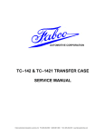
Telephone (925) 454-9500 Fax (925) 454-9501
151 Lawrence, Livermore, CA 94551
www.fabcoautomotive.com
Fabco Automotive Corporation
Service and Parts Manual
Models TC-65, TC-80, TC-110 and PTO-110
TABLE OF CONTENTS
I. Operating Instructions
A. Front Drive
B. Underdrive (TC-65 Only)
C. Power Take-Off
3
3
3
II. Lubrication
A.
B.
C.
D.
E.
F.
Transfer Case Oil Change
Draining Oil
Refilling Oil
Inspection
Operating Temperature
Shift Cylinder Inspection
5
5
5
5
5
5
VII. Torque Specifications
24
VIII. Parts Manual
25
PARTS MANUAL
STARTS ON PAGE 25
Ill. Transfer Case Removal and Installation
A. Removal from Vehicle
B. Installation into Vehicle
6
6
IV. Transfer Case Disassembly
A.
B.
C.
D.
E.
F.
G.
H.
I.
General Precautions for Disassembly
Preparation for Disassembly
Shift Cylinder Disassembly
PTO and Declutch Disassembly
Splitting the Main Housing
Input Shaft Disassembly
Intermediate Shaft Disassembly
Output Shaft Disassembly
Oil Pump Disassembly
7
7
7
8
9
9
10
10
11
V. Cleaning and Inspection
A. Choice of Cleaning Methods
B. Drying and Corrosion Inhibition
C. Inspection
12
12
12
VI. Transfer Case Assembly
A.
B.
C.
D.
E.
F.
G.
General Precautions for Reassembly
Input Shaft Assembly
Intermediate Shaft Assembly
Output Shaft Assembly
Main Housing Assembly
Declutch and PTO Assembly
Shift Cylinder Assembly
and Adjustment
H. Oil Pump Assembly
I. Final Assembly
13
14
15
16
17
20
22
23
23
625 403A Copyright © 1984 by Fabco Automotive, Livermore, California 94551
TC-65, TC-80, TC-110, TRANSFER CASE
PTO-110, SPLIT-SHAFT PTO
TC-65
TC-80
TC-110
TC-OPTIONS
PTO-110
I. OPERATING INSTRUCTIONS
Front Drive
Power Take-Off
When traveling through sand, loose dirt, mud, snow
or ice, or when ascending grades where the rear
wheels might spin, shift to front wheel drive for
better traction. Shift before the truck is in trouble.
Engagement and disengagement of the front axle
can best be made while the engine is pulling lightly.
It can be shifted at any speed provided the rear
wheels are not spinning. An indicator switch is
actuated when the shifter shaft is in the engaged
position.
If the transfer case is equipped with a power take-off
or a PTO mounted hydraulic pump, it can be
operated while the vehicle is moving or stationary.
To engage vehicles fitted with an automatic
transmission, put transmission and transfer case in
gear, apply the brakes and shift the PTO or hydraulic
pump into the engaged position, while the engine is
idling. After the PTO has been engaged, shift the
transmission and transfer case to the desired gear.
An indicator switch is actuated when the shifter
shaft is in the engaged position.
Underdrive (TC-65 only)
To disengage the PTO or hydraulic pump, shift the
transmission to neutral (manual or automatic),
allow the machinery to come to rest, then shift the
control to disengage.
When slow, positive pulling power is desired, shift to
underdrive. Underdrive may be used to obtain a
convenient combination with third or direct for
climbing some grades. The transfer case should be
shifted between high and low range only when the
truck is stopped.
—3—
II. LUBRICATION
Recommended Lubricants
On Highway Vehicles
Type
Grade
Temperature
MIL-L-2104
Heavy-Duty Engine Oil
SAE 50
SAE 30
Above + 10°F.
Below + 10°F.
Mineral
Gear Oil
SAE 90
SAE 80
Above + 10°F.
Below + 10°F.
MIL-L-2105 E.P.
Oil, except Sulfur-chlorine-lead type.
SAE 90
SAE 80
Above + 10°F.
Below + 10°F.
Heavy-duty engine oil. Make sure to specify heavy-duty type meeting MIL-L-2104 specifications.
Mineral gear oil inhibited against corrosion, oxidation and foam.
Off Highway & Mining Equipment
Type
Grade
Temperature
MIL-L-2104
Heavy-Duty Engine Oil
SAE 50
SAE 30
Above + 10°F.
Below + 10°F.
Special Recommendation—For extreme cold weather where temperature is consistently below 0°F:
MIL-L-2104
Heavy-Duty Engine Oil
SAE 20W
—4—
Below 0°F.
II. LUBRICATION
NOTE: Oil Change and Inspection Recommendations:
The oil change and inspection periods described below are based on the average use and operating conditions
the transfer case may encounter. It is recommended that the individual owner make a periodic lab analysis of
the lubricant to determine contamination based on the individual’s own operating conditions. With this data
the individual owner can better determine their own oil change and inspection periods.
A. Transfer Case Oil Change
D. Inspection
Transfer case lubricant should be changed on all
new transfer cases after the first 3,000 to 5,000 miles
(on-highway), or first 40 hours (off-highway); thereafter, oil changes should be done at the following
intervals:
Gear oil level is to be maintained at the level of the fill
plug at all times. Check at the following intervals:
On-Off Highway Service......... 10,000 - 15,000 miles
E. Operating Temperature
Highway Service
Off-Highway Service
Off-Highway Service
(Logging, dirt moving, mining
and associated operations).............. 500-750 hours,
as indicated by operation and contamination of
lubricant.
B. Draining Oil
Draining is best accomplished after the vehicle has
been operated briefly, allowing the oil to become
warm and flow freely. Remove both drain and fill
plugs and allow housing to empty completely. After
transfer case has been drained and before it is
refilled, the case should be thoroughly flushed with
clean flushing oil or kerosene.
1,000 miles
40 hours
The operating temperature of the transfer case
should never exceed 250°F (120°C). Extensive
operation at temperatures exceeding 250°F will
result in rapid breakdown of the oil and shorten
the transfer case life.
F. Shift Cylinder Inspection
With every oil change the air shift cylinder lines and
valves should be inspected for leaks and possible
malfunctioning. Low pressure conditions can cause
partial clutch tooth engagement which may result in
“gear jumping” and premature wear.
C. Refilling Oil
If the transfer case has been removed from the
vehicle for service, it is best to refill the oil after the
transfer case has been reinstalled into the vehicle.
Clean and replace drain plug and fill the transfer
case with appropriate gear oil with the vehicle on
level ground (see recommended lubricant chart).
Fill transfer case to the level of the fill plug, metering
approximately 10½ quarts of gear oil into the
transfer case. The exact amount may differ
depending upon the inclination of the transfer case.
Always fill to the level of the fill plug. Replace fill plug
and examine transfer case for leaks around plugs
and gasket sealed areas.
Do not overfill the transfer case.
—5—
Ill. TRANSFER CASE REMOVAL AND
INSTALLATION
B. Installation into Vehicle
A. Removal from Vehicle
2. Disconnect indicator light wires.
1. Place transfer case on transmission jack and
position jack and transfer case under the
vehicle.
3. Disconnect the air shift lines. Be sure to tag the
lines for future identification.
2. Raise transmission jack and position transfer
case.
4. Disconnect the speedometer cable if it is so
equipped.
3. Connect transfer case mountings. Since mountings vary, consult the vehicle service manual.
5. Disconnect drivelines at flanges.
4. Connect drivelines.
6. If the transfer case is equipped with a PTO
mounted hydraulic pump, remove the four
mounting bolts, slide the pump out of the transfer case and secure pump to the frame and out of
the way.
5. Connect shift cylinder air lines to air cylinders.
1. Remove fill and drain plugs and drain lubricant.
6. Install hydraulic pump to transfer case if it is not
already.
7. Connect indicator light lead wires to terminals.
NOTE: If it is desired, the hydraulic lines can be
disconnected and the pump can be detached
after the transfer case has been removed from
the vehicle.
8. Fill transfer case housing with appropriate lubricant to the correct level and install fill plug.
(Refer to lubrication, Section Il.)
9. Road test the vehicle by driving slowly with no
load for the first few moments, then test at a
higher speed listening for any problems.
7. Position a transmission jack of suitable capacity
beneath the transfer case (800 lb. transfer case).
Be sure that the transfer case is seated safely on
the jack.
10. Check transfer case for leaks around gaskets
and seals.
8. Disconnect transfer case mountings at rubber
insulators. Since mountings vary, consult the
vehicle service manual.
9. Check to ensure that all mountings and connections to the transfer case have been disconnected. Lower the transfer case to the floor and
remove from under the vehicle. It may be
necessary to jack the vehicle up to allow room to
remove the transfer case.
—6—
IV. TRANSFER CASE DISASSEMBLY
A. General Precautions for
Disassembly
The PTO-110 is installed reversed, so TC-110
front is the same as PTO-110 back, and shaft
rotations are reversed. The PTO-110 oil pump is
assembled to pump in reverse rotation, so transfer case and Power Take Off oil pumps are
NOT interchangeable.
IMPORTANT: Read this section before starting the
disassembly procedures.
It is assumed in the disassembly instructions that the
lubricant has been drained from the transfer case
and the transfer case has been removed from the
chassis.
Follow each procedure closely in each section, making use of both tests and pictures. Refer to the exploded views located in Section VIII as an aid in disassembly.
1. The outside of the unit should be cleaned before
starting the disassembly. If steam cleaning,
ensure that breather and air fittings are covered
to prevent water from entering assembly.
B. Preparation for Disassembly
1. After removing the transfer case from the vehicle, remove any mounting brackets still attached
to the transfer case.
2. Remove oil lines if so equipped.
C. Shift Cylinder Disassembly
(High-Neutral-Underdrive)
1. Remove four bolts from the shift cylinder cap
and remove cap from shift cylinder. Discard Oring from cylinder cap, if replacement is necessary.
2. Cleanliness—Provide a clean place to work. It is
important that no dirt or foreign material enters
the unit during repairs.
2. Remove shift cylinder tube from the shift cylinder adapter tube located in the housing, exposing piston.
3. Position the transfer case in a stand suitable to
support the transfer case. A specially fabricated
stand that can rotate the case is extremely useful.
3. Disassemble shift piston from the shift shaft and
discard O-ring and felt wiper, if replacement is
necessary.
4. Assemblies—When disassembling the various
assemblies, lay all parts on a clean bench in the
same sequence as removed. This procedure will
simplify reassembly and reduce the possibility
of lost parts.
4. Remove shift shaft spring and plastic stop ring
from the shift shaft or from the shift cylinder
adapter tube located in the housing.
5. Remove shift cylinder adapter tube from housing. Discard O-rings from the adapter, if replacement is necessary.
5. Bearings—Carefully wash and relubricate all
bearings as removed and protectively wrap until
ready for use. Remove bearings with pullers designed for this purpose, or in a manner which
will not damage those bearings that will be reused.
6. Snap Rings—Remove snap rings with pliers or
special tools designed for this purpose. Rings
removed in this manner can be reused.
7. When necessary to apply a force to remove a
part, use of a puller or press would be preferred.
However, sometimes it may be necessary to use
a soft hammer or mallet.
8. The PTO-110, a variant configuration of the TC110, is used for a Split-Shaft Power Take Off.
Refer to the TC-110 instructions for assembly
and disassembly. Minor differences are noted in
the TC-110 text.
—7—
IV. TRANSFER CASE DISASSEMBLY
D. PTO and Declutch Disassembly
The declutch assembly and PTO are essentially
identical. Hereafter, reference will be made to
the declutch only. For cases equipped with PTO,
use the instructions for declutch disassembly,
inspection and reassembly exactly as given.
1. Remove eight capscrews holding declutch carrier to declutch housing.
2. Tap carrier to loosen and withdraw carrier and
output shaft assembly (see fig. 1).
3. Unscrew indicator light switch from declutch
housing and remove spacer washers. Remove
switch actuator pin from inside declutch housing using a magnet or turn upside down and
dump it out.
Fig. 1
4. Remove four capscrews from declutch cover
plate and remove cover plate.
5. Cut the lockwires and remove the shift fork
clamping screws (see fig. 2).
6. Remove four long capscrews from shift cylinder
and lift off cylinder cap.
7. Withdraw shift piston and shift shaft as a unit.
8. Remove shift cylinder adapter tube and stop
ring, discarding O-rings.
9. Remove nut from shift shaft and lift off the piston
and ‘spring, discarding O-rings and felt wiper.
NOTE: There are two plastic stop rings and no
spring in the PTO-110 cylinders.
Fig. 2
10. Withdraw shift fork and clutch collar (see fig. 3).
11. Remove six capscrews holding declutch housing to main case. Remove the declutch housing
by tapping it with a soft hammer loosening it
from the main case. Remove shims and retain
with housing for later use at assembly.
12. Remove companion flange lock nut and washer
from carrier and output shaft assembly, discarding nut. Use a new nut for reassembly. Slide
companion flange off output shaft.
13. To press output shaft from declutch carrier and
clutch gear, press against threaded end of shaft
while supporting by the clutch gear.
14. Remove output seal, bearings, and end play
spacer from declutch carrier, discarding seal.
Remove bearing cups from the declutch carrier,
only if they are to be replaced.
Fig. 3
—8—
IV. TRANSFER CASE DISASSEMBLY
E. Splitting the Main Housing
1. Remove the declutch and PTO assembly (if so
equipped) from the transfer case (see part D,
this section).
2. Remove the top input flange locknut and washer
and remove flange from shaft. Discard locknut
and replace with a new locknut at assembly. Remove bolts from seal carrier and remove seal
carrier from case. Remove seal from carrier if replacement is necessary.
3. If the transfer case is a two-speed (TC-659,
remove the speedometer driven gear and adapter from the speedometer gear and seal carrier.
The lower rear output flange may now be removed after the locknut and washer have been
removed. Discard locknut and replace with a
new locknut at assembly. Remove bolts from
speedometer gear and seal carrier (TC-65) or
seal carrier (TC-80 and TC-110) and remove carrier. Remove seal from carrier if replacement is
necessary.
Fig. 4
3. Remove locknut and washer from rear of shaft
and slide blanking sleeve from the shaft. Discard
locknut and replace with a new locknut at
assembly. The direct drive gear and remaining
parts can now be disassembled.
4. Remove bolts from the intermediate shaft rear
cap and remove cap. Remove shims and retain
with cap for later use at assembly. Remove oil
pump from cap for further disassembly (see part
I, this section).
5. If the transfer case is not equipped with a PTO,
remove the bolts from the input shaft rear cap
and remove the cap. Remove shims and retain
with cap for later use at assembly.
6. The case should now be supported by the front
half and be positioned so that the rear half of the
case is facing upwards. Mark the housing halves
as a set as these must be reassembled together.
Remove all the bolts that hold the housing
halves together and lift off the rear housing half
(see fig. 4). The three shafts can now be lifted out
of the front half of the case.
NOTE: The stationary shifter shafts, or neutral
gear range shifter shafts will have to be removed
with the input and output shafts.
F. Input Shaft Disassembly
TC-65:
1. Slide underdrive gear, needle bearings and
needle bearing race from front of shaft. If necessary, lift underdrive gear from needle bearing
race. Collect the needle bearings and spacer
ring and place into a container.
2. Side clutch collar and clutch gear from shaft.
—9—
NOTE: The standard case has a splined sleeve
on the rear of the input shaft called a blanking
sleeve. On cases with PTO or direct pump drive
this sleeve is replaced by a gear (identical to the
front output shaft declutch gear) to furnish a
drive for the PTO. Other than having external
teeth to drive the PTO, the declutch gear is
identical to and has the same function as the
blanking sleeve, that of carrying the rear bearing
cone. Hereafter, to simplify technology, the part
will be referred to as the blanking sleeve, even if
it is actually a declutch gear. The front output
part will be referred to as a declutch gear, since a
blanking sleeve is never used in this position.
4. If necessary, remove the roller bearing cone
from the blanking sleeve.
TC-80:
1. Slide the spacing sleeve, clutch gear and clutch
collar from the shaft.
2. Remove locknut and washer from rear of shaft
and slide blanking sleeve from the shaft. Discard locknut and replace with a new locknut at
assembly. The direct drive gear and remaining
parts can now be disassembled.
3. If necessary, remove the roller bearing cone
from the blanking sleeve.
IV. TRANSFER CASE DISASSEMBLY
F. Input Shaft Disassembly (cont.)
TC-110:
TC-110:
HEATING IS NOT REQUIRED FOR REMOVAL OF
THE INTERMEDIATE SHAFT GEAR.
1. Slide the spacer rings and clutch collar from the
front of the shaft.
2. Remove the locknut and washer from the rear of
shaft and, using a puller in the groove provided,
remove the blanking sleeve from shaft. Discard
locknut and replace with a new locknut at
assembly. The direct drive gear and remaining
parts can now be disassembled.
1. Press shaft from the gear and rear roller bearing
cone.
2. Press front bearing from shaft if necessary.
H. Output Shaft Disassembly
TC-65 & TC-80:
3. If inner race and inner thrust washer are not
worn or damaged, do not remove. If replacement
of either is required, the inner race must be
ground, hacksawed or torched off, taking care
not to damage the shaft itself. The inner race
cannot be removed without destroying it.
1. Press shaft from the direct drive gear by placing
the front of the gear on a metal tube and apply
pressure to the rear of the output shaft. Remove
the roller bearing, bearing adapter tube, direct
gear and related parts from the shaft.
4. If necessary, remove the roller bearing cone
from the blanking sleeve.
2. Press the roller bearing cone from the bearing
adapter tube if necessary.
3. Remove locknut and washer from the declutch
gear and remove declutch gear. Discard locknut
and replace with a new locknut at assembly.
Slide spacer sleeve from shaft. If necessary,
press roller bearing cone from the hub of the
declutch gear.
G. Intermediate Shaft Disassembly
NOTE: Intermediate shaft gears are a tight press fit
on the shaft. Disassembly is not advised unless there
is damage to shaft or gears and replacement is
necessary.
TC-65:
TC-110
1. Heat the gears evenly and carefully to 200°F
(93° C) using temperature marker to determine.
2. Press the underdrive gear off the shaft first and
remove the key. This will allow the direct drive
gear and spacer to be pressed off.
IMPORTANT: Do not attempt to press both gears off
at one time. Damage to the shaft, gears and the press
may result.
TC-80:
1. Heat the direct drive gear (as for the TC-65,
above) and press off the shaft.
—10—
1. Slide direct drive gear, spacers and remaining
parts from shaft.
2. Remove the locknut and washer from the
declutch gear and remove declutch gear. Discard the locknut and replace with a new locknut
at assembly. Slide spacer ring from rear of shaft.
If necessary, press roller bearing cone from the
hub of the declutch gear.
3. If inner race and inner thrust washer are not
worn or damaged, do not remove. If replacement
of either is required, the inner race must be
ground, hacksawed or torched off, taking care
not to damage the shaft itself. The inner race
cannot be removed without destroying it.
IV. TRANSFER CASE DISASSEMBLY
I. Oil Pump Disassembly
1. Place pump in a vise, shaft facing up, so that one
jaw grips across two ports. Use care to avoid distorting pump housing by excessive tightening
of vise.
2. Remove any burrs on shaft drive tang.
3. Remove housing plug with a suitable spanner
wrench.
4. Remove from vise and punch match marks (or
paint dab) on cover and body for reassembly.
5. Remove capscrews, cover, idler, and rotor from
housing.
6. Check pump housing, rotor, idler gear, idler
pin and crescent for wear, chipped or broken
teeth.
7. Housing bore and rotor O.D. may be checked for
wear by positioning rotor in the housing and
check for clearance in the bearing. The shaft
must turn freely without any detectable side
play. Any side play will require replacement of
housing, rotor or both. If both housing and rotor
require replacing, it is economically advisable
to replace the pump.
NOTE: The PTO-110 pump has the cover reversed to allow flow in the opposite rotation
direction. Note the position of the notch in the
cover prior to disassembly.
—11—
V. CLEANING AND INSPECTION
A. Choice of Cleaning Methods
C. Inspection
1. Steam may be used for external cleaning of
completely assembled units. Care must be taken
to ensure that water is kept out of the assembly
by tightly closing breather caps and other
openings.
2. Rough parts such as the housing, which are too
large to conveniently clean with solvents, may
be immersed in a hot solution tank containing a
mild alkaline solution. Parts cleaned in hot
solution tanks must be rinsed thoroughly to
prevent damage by traces of alkaline material.
3. Parts with ground or polished surfaces, such as
bearings, gears, and shafts, should be cleaned
with emulsion cleaners or petroleum solvents.
Alkaline hot solution tanks may damage the
machined surfaces and such cleaning methods
should be avoided.
Prior to reassembly, parts which are to be reused
must be carefully inspected for signs of wear or
damage. Replacement of such parts can prevent
costly downtime at a future date.
All bearing surfaces, including roller bearing cups
and cones, should be examined for pitting, wear, or
overheating. Gears also may show pits, as well as
scoring and broken teeth. Shafts may be nicked or
marred, or may have damaged threads. Parts which
show any signs of damage should be repaired or
replaced.
Check all shift forks and slots in sliding clutches for
extreme wear or discoloration from heat. Check
engaging teeth of sliding clutches for partial
engagement pattern.
B. Drying and Corrosion Inhibition
Soft clean shop towels should be used to dry parts
after cleaning. Compressed air may be used to clean
inaccessible areas of large parts such as the housing. Bearings should not be spun dry with
compressed air, as the lack of lubrication may cause
damage to the mating surfaces.
Dried parts should be immediately coated with a
light oil or corrosion inhibitor to prevent corrosion
damage. Parts which are to be stored should also be
wrapped in heavy waxed paper.
—12—
VI. TRANSFER CASE ASSEMBLY
B. Input Shaft Assembly
TC-65 & TC-80:
A. General Precautions for
Reassembly
IMPORTANT: Read this section before starting
reassembly procedure.
Make sure that the interior of the transfer case is
clean. It is important that dirt be kept out of transfer
case during reassembly. Use certain precautions, as
listed below, during reassembly.
1. Gaskets — Clean all gasket surfaces of past
gasket material. Use new gaskets throughout
the transfer case as it is being rebuilt.
2. Bolts — To prevent oil leakage, use Permatex
Form-A-Gasket #2 pliable setting sealant or
equal on all threads. See torque specifications
for recommended torque, Section VII.
3. Assembly — Refer to the exploded views in the
parts manual (Section VIII) as a guide to reassembly.
Fig. 5—TC-65 Input Shaft Assembly with Blanking
Sleeve
4. Initial Lubrication — Coat all thrust washers,
splines and seals with lubriplate during installation to provide initial lubrication, preventing
scoring and galling.
5. Bearings — Press or drive bearing races by
applying force to inner race or outer race,
whichever is being installed.
6. Universal Joint Companion Flanges — Pull the
companion flanges tightly into place with the
locknuts (old locknuts may be used for pulling,
then replaced with new); tighten to proper
torque. Failure to pull the flange tightly into
place will not seat the bearings properly, causing erroneous end play readings and possible
damage to bearings, shafts, and gears.
Fig. 6—TC-65 Input Shaft Assembly with PTO Gear
7. Inspect all spacer washers and rings for wear.
The width or thickness of each spacer washer or
ring has been noted in the assembly procedures
and each spacer should be measured with a
micrometer for proper size. Worn spacers
should be replaced.
8. The clutch collar shift fork slot is offset, which is
indicated in Fig. 5. The long side can be determined by examining the collar for the external
short extended hub. This short hub, referred to
in the assembly instructions, must always face
the mating gear clutch teeth, whether in the declutch housing, PTO housing or main case.
Fig. 7—TC-80 Input Shaft Assembly with PTO Gear
—13—
VI. TRANSFER CASE ASSEMBLY
rear of the shaft. Slide the clutch collar onto the
teeth of the clutch gear. The side of the collar
with the short hub is to face the rear of the shaft
(see fig. 5)
B. Input Shaft Assembly (continued)
TC-65 & TC-80: (See Fig. 5, 6 and 7)
1. Place input shaft thrust washer (.148 thick) on
bench. Liberally grease inside diameter of
direct drive and outside diameter of needle
bearing race. Place front of direct drive gear
(side of gear with clutch teeth) on thrust washer.
Place needle bearing race inside the gear with
the bearing race lock pin facing the rear of the
gear (or up). Grease needle bearings and install
a row of needle bearings between gear and race.
NOTE: Install 62 needle bearings only in each
row. One extra needle can be packed into each
row, but this makes the rollers too tight, invariably causing rubbing, heating and eventual
failure of the bearing pack, gear and shaft.
6. Place direct drive gear assembly (including gear
spacer ring and thrust washer) over the shaft
aligning inner race lock pin with elongated
groove in shaft and against the clutch gear. The
clutch teeth of the gear must face the front of the
shaft.
7. Press the bearing cone over the blanking sleeve
hub and slide the sleeve over the shaft splines
and secure with the washer and locknut. Tighten
nut to correct torque. Check thrust washer
clearance as above, .015-.020.
8. Set the shaft aside for installation into the front
half of the main case. Refer to Part E, page 16, for
this assembly. Remove the flange from the shaft
that was used to support the shaft during assembly, making sure to retain underdrive gear,
needles and inner race in position.
Install a spacer ring, tap the needle bearings and
spacer ring against the shoulder of the race with
a punch and install next row of bearings.
2. Place gear spacer ring (3/8" thick) on top of gear
assembly with chamfered inside diameter facing
inside of gear.
3. Two-speed case only (TC-65): Grease inside
diameter of underdrive gear and outside
diameter of needle bearing race. Place needle
bearing race on the bench with the flange facing
down. Place underdrive gear onto the race with
the clutch teeth facing up. Grease needle bearings and install a row of needle bearings between gear and race.
NOTE: Install 62 needle bearings only in each
row. One extra needle can be packed into each
row, but this makes the rollers too tight, invariably causing rubbing, heating and eventual
failure of the bearing pack, gear and shaft.
Install a spacer ring, tap the needle bearings and
spacer ring against the shoulder of the race with
a punch and install next row of bearings.
Fig. 8
4. Two-speed case only (TC-65): Install the front
side of the input shaft (short journal) through the
underdrive gear assembly. (The flange of the
underdrive gear inner bearing race is to face the
front of the shaft and the clutch teeth of the gear
are to face the center of the shaft). Align the
inner race lock pin with the elongated groove in
the journal and slide gear on all the way. With
inner race pressed tightly against inner thrust
washer, check with a feeler gauge for .015-.020
clearance between gear hub and thrust washer.
5. For ease in assembly, use a companion flange
from the transfer case as a stand for the shaft.
Slide the flange onto the front of the shaft and
stand the shaft upright. Slide the clutch gear
onto the raised teeth of the shaft. The jump lock
portion of the teeth (see fig. 8) are to face the
Fig. 9—TC-110 Input Shaft Assembly
—14—
VI. TRANSFER CASE ASSEMBLY
B. Input Shaft Assembly (continued)
TC-110: (see fig. 9)
1. If the inner thrust washer and needle bearing
race have been removed from the rear of the
input shaft, place the thrust washer (.148" thick)
over the shaft and against the raised teeth of the
gear. Oil groove side of washer to face outwards
and toward where the direct drive gear will be
placed. Heat the inner race in an oven to about
200-250°, drop over shaft and tap down to the
inner thrust washer with a suitable driver (the
roller bearing inner race must be snug against
the inner thrust washer).
2. Slide two roller bearing assemblies and spacer
ring over the roller bearing inner race located at
the rear of the shaft. Grease the roller bearing
assemblies and the inner diameter of the direct
drive gear. Slide the gear over the rear of the
shaft. Place the gear spacer ring (5&” thick) over
the rear of the shaft and against the gear. Oil
groove side of washer must face gear.
Tap underdrive gear woodruff key into the slot.
Heat underdrive gear in oil (or in an oven) to
200°F (93°C) and press the shaft into the gear
by placing front of the gear (flat side) on a metal
tube and applying pressure to the rear of the
shaft. Be sure the woodruff key is mating properly with the slot in the gear.
TC-80 only: Slide gear spacer (315/32” long) over
front of shaft and against direct drive gear.
3. Place spacer ring (V8” thick) over front of shaft
and against gear spacer. (Fits on smallest hub.)
Inner diameter chamfer of ring to face gear.
4. Press roller bearing cone onto the front of the
shaft. Press roller bearing cone onto the rear of
the shaft.
5. Set the shaft assembly aside for installation into
the front half of the main housing. Refer to part
E, page 15 for this assembly.
3. Press the roller bearing cone over the blanking
sleeve. Slide the blanking sleeve onto the splines
located at the rear of the shaft. Secure blanking
sleeve to shaft with the washer and locknut.
Tighten locknut to correct torque. Check thrust
clearance as before, .015-.020.
4. Slide clutch collar over the front of the shaft and
over the raised teeth of the input shaft (short hub
to face direct drive gear, see fig. 5). Slide spacer
ring (21/32” thick) over front of shaft and onto the
raised teeth of shaft. Slide spacer ring (13’/32”
thick) over front of shaft and onto the raised hub
portion of the shaft past the splines. The inner
diameter chamfer of the spacer is to face the
direct drive gear.
5. Set the input shaft aside for installation into the
front half of the main case. Refer to part E, page
16 for this assembly. (Be sure to hold the front
spacer ring as the shaft is dropped into the front
of the case so the parts do not slide from the
shaft.)
Fig. 10—TC-65 intermediate Shaft Assembly
C. Intermediate Shaft Assembly
TC-65 & TC-80: (See fig. 10 and fig. 11)
1. Tap direct drive gear woodruff key into the slot
located in the center of the shaft. Heat direct
drive gear in oil (or in an oven) to 200°F (93” C).
Press the shaft into the gear by placing the front
of the gear (coned side) on a metal tube and
applying pressure to the rear of the shaft. Be
sure the woodruff key is mating properly with
the slot in the gear.
2. TC-65 only: Slide the spacer ring (.333 thick)
over front of shaft and against direct drive gear.
Fig. 11—TC-80 intermediate Shaft Assembly
—15—
VI. TRANSFER CASE ASSEMBLY
D. Output Shaft Assembly
C. Intermediate Shaft Assembly
(continued)
TC-65 & TC-80:
TC-110
(See fig. 13)
1. Press tapered roller bearing cone onto the declutch gear hub. Slide spacer sleeve over the
shaft (short journal) and against the raised teeth
of the shaft. Slide declutch gear onto splines of
the lower shaft next to spacer sleeve. Secure declutch gear to shaft with the washer and locknut.
Tighten to correct torque.
2. Stand the shaft upright on the declutch gear.
Slide the clutch collar over the shaft and allow to
set on the roller bearing. Slide the clutch gear
onto the raised teeth of the shaft. Be sure the
jump lock is facing up or toward the end of the
shaft where the direct drive gear will be located
(see fig. 8).
3. Liberally grease the inside diameter of the direct
drive gear and outside diameter of the needle
bearing race. Place the direct drive gear thrust
washer (.148" thick) on a bench and place the
direct drive gear on top of the washer (side of
gear with clutch teeth to be against washer).
Place needle bearing race inside the gear with
the bearing race lock pin nearest the top of the
gear. Grease needle bearings and install one
row of needle bearings (see input shaft assembly note) at a time between gear and race. Install
a spacer ring after each row. Slide this assembly
onto the shaft with the clutch teeth of the gear
facing down. Align the pin in the groove and
push the gear as far as possible onto the shaft.
Fig. 12—TC-110 intermediate Shaft Assembly
1. Slide spacer ring over the rear of the shaft and
against the shoulder of the shaft, with the inside
chamfer facing toward the center of the shaft.
2. Slide gear over the splines on the shaft.
3. Press rear roller bearing cone over the rear of the
shaft. Press front roller bearing cone over the
front of the shaft.
4. Press the roller bearing cone assembly onto the
bearing adapter tube. Install this assembly onto
the rear of the output shaft by tapping with a soft
hammer. Check thrust clearance as on input
shaft, .015-.020.
4. Set the shaft assembly aside for installation into
the front half of the main housing. Refer to Part
E, page 16 for this assembly.
5. Set shaft aside for assembly into the front half of
the main housing. Refer to Part E, page 16 for
this assembly.
TC-110:
(See fig.14)
1. If the inner thrust washer and needle bearing
inner race have been removed from the rear of
the output shaft, place the thrust washer (.148
thick) over the shaft and against the raised teeth
of the shaft. Oil groove side of washer must face
outwards and toward where the direct drive gear
will be placed. Heat the inner race in an oven to
about 200-250°, drop over shaft and tap down to
inner thrust washer with a suitable driver (the
roller bearing inner race must be snug against
the inner thrust washer).
Fig. 13—TC-65 and TC-80 Output Shaft
Assembly
—16—
VI. TRANSFER CASE ASSEMBLY
2. Slide spacer ring (131/32” thick) over front of
shaft and onto the raised hub portion of the shaft
past the splines. The inner diameter chamfer of
the spacer is to face the center of the shaft.
2. Press a new seal into the input shaft seal carrier.
Assemble seal carrier to front half of housing
with six bolts. Be sure to align oil passage and
grooves. Tighten bolts to correct torque.
3. Press the roller bearing cone over the hub of the
declutch gear. Slide the declutch gear onto the
splines located at the front of the shaft. Secure
declutch gear to shaft with the washer and locknut. Tighten locknut to correct torque.
3. Assemble intermediate shaft front cap to front
half of housing with nine bolts. Tighten bolts to
correct torque. (Six bolts for 110 only.)
4. Slide spacer ring (2’/32” thick) over rear of shaft
and onto the raised teeth of the shaft (not used
on PTO-110). Slide clutch collar over the rear of
the shaft and over the raised teeth of the shaft.
Short hub side of collar (see fig. 5) to face toward
where the direct drive gear will be placed.
5. Slide two roller bearing assemblies and spacer
ring over the roller bearing inner race located at
the rear of the shaft. Grease the roller bearing
assemblies and the inner diameter of the direct
drive gear. Slide the gear over the rear of the
shaft. Place the gear spacer ring (5/8” thick) over
the rear of the shaft and against the gear. Oil
groove side of washer must face gear. Install
flange, washer, and nut, and torque to specification. Check clearance as in input shaft assembly
.015-.020 clearance. Remove nut, washer and
flange.
4. Place an O-ring into the groove of each shift
adjustment cap. Smear lubriplate or grease all
around the O-ring and install into the housing,
securing with 4 bolts for each cap.
NOTE: The PTO-110 does not use shift adjustment caps.
Install a jam nut onto each adjusting bolt and
start the adjusting bolt into each cap.
5. Position front half of housing with the inside
facing up.
6. Set the shaft assembly aside for installation into
the front half of the case.
Fig. 15
Fig 14—TC-110 Output Shaft Assembly
E. Main Housing Assembly
NOTE: Housing halves are matched at the factory
and should be replaced as pairs only.
1. Install bearing cups into each half of the main
housing. Install bearing cup into the bearing cup
adapter and tap assembly into housing bore for
Fig. 16
the intermediate shaft located in the front half of
the main housing (TC-65 & 80 only).
—17—
VI. TRANSFER CASE ASSEMBLY
6. Reassemble the shift fork and shift shaft assembly if it has been disassembled. Place the proper
shift fork onto the clutch collar on the input and
output shafts.
11. TC-65 only: Press seal into output shaft rear seal
speedometer gear carrier. Assemble gasket and
carrier to housing with six bolts. Be sure to align
7. Place input shaft front bearing cone into bearing
race. Place the input shaft, intermediate shaft
and output shaft assemblies into the front half of
housing in that order (see fig. 16).
TC-110 only: Place roller bearing on rear of output shaft.
8. Install main housing gasket with sealer and
place rear half of main housing over shaft
assemblies and onto the front half guiding shift
rails through bores (see fig. 17). Secure two
halves together with the shoulder bolts and 12
point capscrews. Tighten bolts to correct
torque.
9. Tap input shaft down to seat the shaft into the
bearings. Place the PTO housing or rear cap into
the input shaft rear housing bore. Measure with
feeler gauges the amount of clearance between
the cap and the housing (see fig. 18 and 19). Add
.005” to this dimension and add the necessary
shims to match that calculated dimension.
Assemble PTO housing or rear cap to housing
and secure with the proper bolts. Tighten bolts
to correct torque. See Part F, this section for
PTO assembly.
10. Tap intermediate shaft down to seat the shaft
into the bearings and related parts. Place intermediate shaft rear cap into the rear housing
bore. Measure with feeler gauges the amount of
clearance (see fig. 20). Add .005” to this dimension and add the necessary shims to match that
calculated dimension. Assemble rear cap to
housing and secure with six bolts. Be sure to
align the oil passages. Tighten bolts to correct
torque.
Fig. 17
Fig. 18
Fig. 19
Fig. 20
—18—
VI. TRANSFER CASE ASSEMBLY
panion flange with a washer and locknut (see fig.
21). Tighten locknut to correct torque. Assemble
speedometer driven gear and adapter to carrier
(see fig. 22).
the oil passages. Assemble speedometer gear
spacer and speedometer drive gear to the companion flange. Assemble the rear output com-
12. TC-80 & 110 only: Press seal into output shaft
rear seal carrier. Assemble seal carrier and
gasket to housing with six bolts. Be sure to align
oil passages. Tighten bolts to correct torque.
Slide rear output companion flange onto the
splines (TC 110 must be started into the rear
bearing cone and driven in). Secure flange with
washer and locknut. Tighten locknut to correct
torque.
13. Turn housing assembly over to position front of
case facing up.
Fig. 21
14. Slide front input companion flange onto the
splines, start flange into the front bearing cone
inner race and secure flange with washer and
locknut. Tighten locknut to correct torque (see
fig. 23).
15. Tap output shaft down to seat the shaft into the
bearings and related parts. Place the declutch
housing into the output shaft front housing bore.
Measure with feeler gauges the amount of clearance between declutch housing and main
housing. Add .005” to this dimension and add
the necessary shims to match the calculated
dimension. Assemble declutch housing to main
housing and secure with the proper bolts. Tighten bolts to correct torque. See Part F, this section for declutch assembly.
16. Turn housing over to position rear of housing
face up. Place an O-ring into the shift adjustment cap(s) and insert into rear half of housing.
Secure with four bolts for each cap. Assemble a
jam nut loosely on each adjusting bolt and screw
the bolt into the adjustment cap(s). Adjust nonmovable shift shafts by running the bolt at the
back of the case outward until it protrudes at
least 1½ inches. Turn the front bolt inward until
the shaft meets resistance, then back it out ½
turn and lock it. Turn the back bolt inward until it
meets the shift shaft, then back it out ½ turn and
lock it. Check for binding by turning the shafts.
See section VI, G, for shift shaft adjustment.
Fig. 22
17. Install oil pump (if so equipped) and gasket to
rear intermediate shaft cap if oil pump has been
removed.
Fig. 23
—19—
VI. TRANSFER CASE ASSEMBLY
F. PTO and Declutch Assembly
8. Place piston over threads of shift shaft (depressing spring) with shallower of two grooves
facing towards shaft (Fig. 29).
NOTE:The PTO and declutch assemblies are similar
except for the manner in which the housings are
bolted to the transfer case. See fig. 24 and 25 for
mounting of appropriate housing.
1. Bolt PTO/declutch housing and gasket to main
case with six capscrews. Be sure to align oil passages (see fig. 24). Tighten capscrews to correct
torque.
2. Slide clutch collar into the shift fork ears and
assemble the two parts together into the declutch housing (see fig. 26). The short hub on
the collar must face the housing and the flat side
of the fork must face away from the housing. The
shift fork is not symmetrical and it is possible to
install it backward. Even if the shaft and adapter
will assemble, the fork will interfere with the
inside of the declutch housing and cause incomplete or erratic shifting.
3. Install shift shaft through shift fork and into declutch housing. Align two grooves in shaft with
clamping screw holes.
Fig. 25—Housing to Transfer Case Location
4. Install two shift fork clamping screws and tighten to correct torque. Secure clamp screws with
lockwire (see fig. 27).
NOTE: If the clamping screws are not easily
accessible through the side cover as shown in
fig. 27, the fork is installed backward.
5. Install O-rings in adapter tube and insert adapter
tube into declutch housing (see fig. 28).
6. Place small O-ring over threads of shifter shaft.
7. Place stop ring over shift shaft and place spring
over end of shift shaft.
NOTE: The PTO-110 does not have a spring. But
has two plastic stop rings, one on each side of
the piston.
Fig. 26
Fig 24—Declutch Housing to Transfer Case Location
Fig. 27
—20—
VI. TRANSFER CASE ASSEMBLY
9. Install shift shaft nut and washer. Tighten nut to
correct torque.
20. Press roller bearing onto output shaft and insert
declutch carrier onto output (see fig. 31).
10. Place an oil soaked felt wiper in shallow groove
on piston and an O-ring into deep groove (see
fig. 29).
NOTE: Since it takes some time to soak the felt
wiper long enough to expand and soften enough
to fill the groove it is a good idea to do this ahead
of time. Also, the felt wiper will not necessarily
fill the groove the entire circumference of the
piston.
11. Coat the shift cylinder tube lightly with gear lubricant. Place cylinder tube over piston and over
adapter tube. (Use care not to cut or displace Orings.)
12. Install O-ring in shift cylinder cap.
13. Install cylinder cap on cylinder tube with four
long capscrews, tightening to correct torque.
Tighten capscrews evenly to prevent cocking
the cylinder cap.
Fig. 29
14. Apply cover plate gasket to declutch housing.
15. Install cover plate with four capscrews, tightening to correct torque.
16. Insert plunger into indicator switch hole with
rounded side of plunger against the shift shaft.
17. Install indicator switch, shimming with copper
washers as necessary for proper operation.
Check with continuity indicator.
18. Press bearing cups into declutch carrier.
19. Install snap ring on output shaft and slide clutch
gear onto output shaft. Flat side of gear to face
up (see fig. 30).
Fig. 30
Fig. 28
Fig. 31
—21—
VI. TRANSFER CASE ASSEMBLY
21. Place end play spacer through front of declutch
carrier and on top of inner roller bearing.
22. Press outer roller bearing onto output shaft and
into declutch carrier.
NOTE: The declutch and PTO output shaft bearings
need no adjustment as the bearing spacer is factory
selected for proper end play. If the bearings have
been replaced assemble the output shaft in its
carrier with output flange installed, torque the
output flange nut to specification, and check the end
play. Use a .323 thick spacer for the first check.
Experience has shown that this gives the proper end
play in 75% of assemblies the first time. If it is more
than .005 inch or less than .003 inch, substitute a
spacer with another thickness and recheck. Spacers
of .313, .318, .323 and .328 inch thickness are available. (The PTO-110 has different bearings, and uses
spacers of .360 to .385 thickness in .005 increments.)
23. Install drive flange seal with an appropriate
driver.
Fig. 32
24. Coat the flange hub with gear lubricant. Install
drive flange onto output shaft with nut and lockwasher. Tighten nut to correct torque.
25. Apply gasket to housing assembly and install
declutch carrier with eight capscrews, tightening to correct torque. Declutch carrier must be
installed so oil seal drain passage is to the
bottom of the case (see fig. 32).
G. Shift Cylinder Assembly and
Adjustment
1. Screw adjusting bolt on adjustment cap located
at input (front) side of case in until the bolt stops.
2. Install two O-rings onto shift cylinder adapter
tube, coat adapter tube with gear lubricant, and
install tube into rear of housing (see fig. 33).
Fig. 33
3. Place small O-ring over threaded end of shift
shaft and against shift shaft shoulder.
4. Place spring over end of shift shaft and into
adapter. Place plastic stop ring over spring.
NOTE: PTO-110 does not have springs, but has
two plastic stop rings, one on each side of piston.
5. Place piston over shift shaft with the shallower of
the two grooves toward the shaft. Make sure
small O-ring on shaft is seating in chamfer in
piston bore. Depress the spring with the piston
and secure piston with the washer and locknut.
Tighten locknut to correct torque. Place an oil
soaked felt wiper in shallow groove on piston
and an O-ring in the deep groove (see fig. 34).
Fig. 34
—22—
VI. TRANSFER CASE ASSEMBLY
I. Final Assembly
6. Coat the shift cylinder tube lightly with lubricant, install cylinder tube over-piston and seat
cylinder tube over O-ring in the adapter tube.
Install O-ring in shift cylinder cap and install
cylinder cap into the cylinder tube. Secure
assembly with bolts and tighten bolts evenly to
prevent misalignment of cylinder cap. Tighten
bolts to correct torque.
1. Attach all mounting brackets that must be
secured to the transfer case before the case can
be installed in the truck.
2. Install temperature sensor if vehicle is so
equipped.
7. Unscrew adjusting bolt at input (front) side of
case until approximately 1½ inches protrude
from housing. Be sure that bolt end is not touching the end of the shaft at full stroke with air
applied to the cylinder.
3 . Prior to plumbing, prime oil pump and fill filter
cup with oil can.
4 . Connect oil pump lines.
5. Refer to Section III, Part B and install transfer
case into vehicle.
8. Apply air pressure to the cylinder. Run the adjusting bolt in until the end of the bolt makes
contact with the shift shaft in the case. Turn the
bolt inward ½ turn from this point and tighten
the jam nut.
H. Oil Pump Assembly
1. Install rotor in pump body.
2. Apply gasket(s) to cover.
3. Place idler gear on pin in cover assembly.
4. Place cover assembly with idler gear on pump
housing. Use care to align matching marks for
proper location. Insure the cover notch is in
same position as when removed.
5. Install cover plate capscrews securely. Pull
down gradually and alternate from a screw on
one side to one on the opposite side.
6. Install and tighten housing plug with appropriate spanner wrench.
7. Check pump for free rotation by turning shaft
(shaft should turn freely by hand without binding). Rotor end play of .003-.010” can be obtained by adding or removing cover plate
gaskets.
8. Secure oil pump and gasket to rear intermediate
shaft cap.
—23—
VII. TORQUE SPECIFICATIONS
Location
Bolt Size
Air shift cylinder attach bolts
(varies)
Hexagon Head
*Torque
(lb.-ft.)
12
Declutch housing inspection plate bolts
10
Declutch to case bolts
60
Front drive/PTO/pump carrier unit and
all end cap bolts
60
point
Transfer case housing bolts
95
Flange retaining nuts and declutch
gear retaining nuts (TC-65 and TC-80)
Hex
325
Flange retaining nuts (TC-110 & TC-80)
Hex
400
265
Transfer case mounting angle attach bolts
*Torques given apply to parts coated with machine oil. For dry parts increase torque 10%.
—24—