1
Telephone (925) 454-9500 Fax (925) 454-9501
151 Lawrence Drive, Livermore, California 94551
www.fabcoautomotive.com
Fabco Automotive Corporation
Service and Parts Manual
Models TC-160 and PTO-160
TABLE OF CONTENTS
I.
A.
B.
C.
II.
VII. Torque Specifications . . . . . . . . . . . . . . . . . . . . . . . 30
Operating Instructions
Front Drive . . . . . . . . . . . . . . . . . . . . . . . . . . . . . . . . . 5
Transfer Case PTO . . . . . . . . . . . . . . . . . . . . . . . . 5
PTO-160 Split Shaft . . . . . . . . . . . . . . . . . . . . . . 5
PARTS M A N U A L
Lubrication
A.
B.
C.
D.
E.
F.
G.
Recommended Lubricants . . . . . . . . . . . . . .
Transfer Case Oil Change . . . . . . . . . . . . . .
Draining Oil . . . . . . . . . . . . . . . . . . . . . . . . . . . . . . . . .
Refilling Oil . . . . . . . . . . . . . . . . . . . . . . . . . . . . . . . . .
Inspection . . . . . . . . . . . . . . . . . . . . . . . . . . . . . . . . . .
Operating Temperature . . . . . . . . . . . . . . . . . .
Shift Cylinder Inspection . . . . . . . . . . . . . . . . .
STARTS ON PAGE 31
6
7
7
7
7
7
7
III. Transfer Case Removal and Installation
A.
B.
Removal from Vehicle . . . . . . . . . . . . . . . . . . .
Installation into Vehicle . . . . . . . . . . . . . . . . . .
8
8
IV. Transfer Case Disassembly
A.
B.
C.
D.
E.
F.
G.
H.
General Precautions for Disassembly
Preliminary Disassembly . . . . . . . . . . . . . . . .
Shift Cylinder Disassembly . . . . . . . . . . . . . .
PTO and Declutch Disassembly . . . . . . .
Main Housing Disassembly . . . . . . . . . . . .
Main Shaft Removal . . . . . . . . . . . . . . . . . . . . . .
Shaft Disassembly . . . . . . . . . . . . . . . . . . . . . . .
Lubrication Pump Disassembly . . . . . . . . .
9
9
10
10
11
12
13
14
V. Cleaning and Inspection
A.
B.
C.
VI.
Choice of Cleaning Methods . . . . . . . . . . . 15
Drying and Corrosion Inhibition . . . . . . . . 15
Inspection . . . . . . . . . . . . . . . . . . . . . . . . . . . . . . . . . 15
Transfer Case Assembly
A.
B.
C.
D.
E.
F.
G.
General Precautions for Reassembly . . . .
Shaft Assembly . . . . . . . . . . . . . . . . . . . . . . . . . . .
Installation into Housing . . . . . . . . . . . . . . . . . .
Shimming Shafts . . . . . . . . . . . . . . . . . . . . . . . . . .
Shift Cylinder Assembly & Adjustment.
PTO & Declutch Assembly . . . . . . . . . . . . .
Oil Pump Assembly and Installation.....
16
16
17
25
26
27
29
— 1—
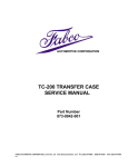
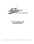
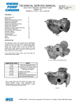
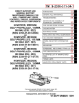
DIRECT PUMP DRIVE OPTIONAL
FRONT VIEW
OPTIONS:
FLANGES 1710 OR 1810 SERIES.
NEUTRAL CAPABILITY
LUBRICATION SYSTEM ( PRESSURE )
POWER TAKE-OFF
DIRECT DRIVE PUMP
PTO OPTIONAL
PTO OPTIONAL
SIDE VIEW ( L H )
BASIC
REAR VIEW
DUAL- DIRECT PUMP DRIVE OPTIONAL
REAR VIEW
DUAL PTO OPTIONAL
SIDE VIEW (RH)
PTO WITH DIRECT DRIVE PUMP OPT IONAL
FRONT VIEW
FRONT DECLUTCH
SHIFT DETAILS
OPTIONAL LUBRICATION PUMP
I. O P E R A T I N G I N S T R U C T I O N S
B. Transfer Case PTO
If the transfer case has a PTO or Direct Pump Drive,
the PTO may be operated with the vehicle stationary
or moving, depending on how the air shift controls are
arranged. If there is only one valve lever labeled PTO/NEUTRAL, the PTO and Neutral actuating cylinders
are operated together by one valve; PTO operation is
only possible when the transfer case is in Neutral. If
two valves are present, labeled PTO and NEUTRAL
separately then the operator has a choice of PTO
while moving or in stationary operation. Moving PTO
operation is limited by the fact that engine speed for
ground movement may not be the best speed for the
PTO operation.
To engage the PTO (single valve operation) stop the
vehicle, set the brakes, shift to PTO/NEUTRAL and
shift the transmission to the desired gear. If the vehicle
has an automatic transmission, it may be necessary
to shift the gear selector to Neutral momentarily to
allow the PTO and Neutral to shift. An indicator switch
is actuated when the PTO shift shaft is in the engaged
position.
To disengage the PTO (one valve), stop the drive train
by shifting the transmission to Neutral. Allow the shafts
to come to rest, and shift the PTO/NEUTRAL valve to
disengage. This automatically re-engages the rear
axle.
If separate PTO and Neutral valves are used, operation is the same as with one valve, except the Neutral
valve can be selected independently of the PTO.
A. Front Drive
C. PTO-160 Split-Shaft PTO
When traveling through sand, loose dirt, mud, snow or
ice, or when ascending grades where the rear wheels
might spin, shift to front wheel drive for better traction.
Shift before the truck is in trouble. Engagement and
disengagement of the front axle can best be made
while the engine is pulling lightly. It can be shifted at
any speed provided the rear wheels are not spinning.
An indicator switch is actuated when the shifter shaft
is in the engaged position.
The PTO-160 is equipped with double-acting cylinders requiring four-way valves for control. Operation of
the PTO-160 is the same as the operation of the
transfer case PTO or Direct Pump Drive. The rear
axle disconnect is in the declutch housing on the rear
of the PTO-160.
If separate PTO outputs require separate operation,
there will be a control for each. Operation is still the
same.
—5—
II. L U B R I C A T I O N
On Highway Vehicles
Type
Grade
Temperature
MIL-L-2104
Heavy-Duty Engine Oil
SAE 50
SAE 30
Above + 10°F.
Below + 10°F.
Mineral
Gear Oil
SAE 90
SAE 80
Above + 10°F.
Below + 10°F.
MIL-L-2105 E.P.
Oil, except Sulfur-chlorine-lead type.
SAE 90
SAE 80
Above + 10°F.
Below + 20°F.
Heavy-duty engine oil. Make sure to specify heavy-duty type meeting MIL-L-2104 specifications.
Mineral gear oil inhibited against corrosion, oxidation and foam.
Off Highway & Mining Equipment
Type
Grade
Temperature
MIL-L-2104
Heavy-Duty Engine Oil
SAE 50
SAE 30
Above + 10°F.
Below + 10°F.
Special Recommendation--For extreme cold weather where temperature is consistently below 0°F.
MIL-L-2104
Heavy-Duty Engine Oil
SAE 20W
Below 0°F.
MIL-L-2105 C
SAE 75W-90
Below 0°F.
—6—
II. L U B R I C A T I O N
NOTE: Oil Change and Inspection Recommendations:
The oil change and inspection periods described below are based on the average use and operating
conditions the transfer case may encounter. It is recommended that the individual owner make a periodic lab
analysis of the lubricant to determine contamination based on the individual's own operating conditions.
With this data the individual owner can better determine their own oil change and inspection periods.
B. Transfer Case Oil Change
E. Inspection
Transfer case lubricant should be changed on all new
transfer cases after the first 3,000 to 5,000 miles (onhighway), or first 40 hours (off-highway); thereafter, oil
changes should be done at the following intervals:
Gear oil level is to be maintained at the level of the fill
plug at all times. Check at the following intervals:
On-Off Highway Service . . . . 10,000 - 15,000 miles
Off-Highway Service
(Logging, dirt moving, mining
and associated operations) . . . . . . . 500-750 hours,
as indicated by operation and contamination of
lubricant.
C. Draining Oil
Draining is best accomplished after the vehicle has
been operated briefly, allowing the oil to become
warm and flow freely. Remove both drain and fill plugs
and allow housing to empty completely. After transfer
case has been drained and before it is refilled, the
case should be thoroughly flushed with clean flushing
oil or kerosene.
If case is equipped with an oil pump, the lube oil filter
should be replaced whenever the oil is changed. The
filter element is a spin-on type. A film of clean oil
should be applied to the rubber gasket seat of the new
element before installing.
Highway Service . . . . . . . . . . . . . . . . . . . .
Off-Highway Service . . . . . . . . . . . . . . . . . . .
1,000 miles
40 hours
F. Operating Temperature
The operating temperature of the transfer case (or
PTO) should never exceed 250°F (120°C). Operation
at temperatures exceeding 250°F will result in rapid
breakdown of the oil and shorten the transfer case life.
If the case is equipped with a lubricating pump, an oil
cooler may be plumbed into the circuit, on the output
side of the pump. The PTO-160 is standard with a lube
pump, and should always have an oil cooler, if operating temperature runs over 250°F.
G. Shift Cylinder Inspection
With every oil change the air shift cylinder lines and
valves should be inspected for leaks and possible
malfunctioning. Low pressure conditions can cause
partial clutch tooth engagement which may result in
"gear jumping" and premature wear.
D. Refilling Oil
If the transfer case has been removed from the vehicle
for service, it is best to refill the oil after the transfer
case has been reinstalled into the vehicle.
Clean and replace drain plug and fill the transfer case
with appropriate gear oil with the vehicle on level
ground (see recommended lubricant chart). Fill
transfer case to the level of the fill plug, metering
approximately 10 quarts of gear oil into the transfer
case. The exact amount may differ depending upon
the inclination of the transfer case. Always fill to the
level of the fill plug. Replace fill plug and examine
transfer case for leaks around plugs and gasket
sealed areas.
Do not overfill the transfer case.
—7—
III. TRANSFER CASE REMOVAL A N D
INSTALLATION
B. Installation into Vehicle
A. Removal from Vehicle
1. Place transfer case on transmission jack and
position jack and transfer case under the vehicle.
1. Remove fill and drain plugs and drain lubricant.
2. Disconnect indicator light wires.
2. Raise transmission jack and position transfer
case.
3. Disconnect the air shift lines. Be sure to tag the
lines for future identification. Disconnect oil
cooler lines if present.
3. Connect transfer case mountings. Since mountings vary, consult the vehicle service manual.
4. Disconnect drivelines at flanges.
4. Connect drivelines.
5. If the transfer case is equipped with a PTO
mounted hydraulic pump, remove the mounting
bolts, slide the pump out of the transfer case and
secure pump to the frame and out of the way.
5. Connect shift cylinder air lines to air cylinders.
6. Install hydraulic pump to transfer case if it is not
already.
NOTE: If it is desired, the hydraulic lines can
be disconnected and the pump can be
detached after the transfer case has been
removed from the vehicle,
7. Connect indicator light lead wires to terminals.
6. Position a transmission jack of suitable capacity
beneath the transfer case (800 lb. transfer case).
Be sure that the transfer case is seated safely on
the jack.
7. Disconnect transfer case mountings at rubber
insulators. Since mountings vary, consult the
vehicle service manual.
8. Check to ensure that all mountings and connections to the transfer case have been disconnected. Lower the transfer case to the floor and
remove from under the vehicle. It may be necessary to jack the vehicle up to allow room to
remove the transfer case.
—8—
8. Fill transfer case housing with appropriate lubricant to the correct level and install fill plug. (Refer
to lubrication, Section II.)
9. Road test the vehicle by driving slowly with no
load for the first few moments, then test at a
higher speed listening for any problems.
10. Check transfer case for leaks around gaskets
and seals.
IV. TRANSFER CASE DISASSEMBLY
A. General Precautions for
Disassembly
6. Snap Rings—Remove snap rings with pliers or
special tools designed for this purpose. Rings
removed in this manner can be reused.
IMPORTANT: Read this section before starting
the disassembly procedures.
7. When necessary to apply a force to remove a
part, use of a puller or press would be preferred.
However, sometimes it may be necessary to use
a soft hammer or mallet.
It is assumed in the disassembly instructions that the
lubricant has been drained from the transfer case and
the transfer case has been removed from the chassis.
8. The PTO-160, the Split-Shaft Power Take-Off
version of the TC-160, is different only in use of
double-acting cylinders instead of single-acting,
a larger capacity lubrication pump (otherwise
identical to that of the TC-160), and that it is
installed in reversed position from the transfer
case. Disassembly and assembly procedures
are identical, except that all references to front or
back of the transfer case will be reversed when
working on a PTO-160. Especially, the front axle
declutch on the transfer case is the rear axle
declutch on the SSPTO.
Follow each procedure closely in each section,
making use of both text and pictures. Refer to the
views located in the Parts Manual as an aid in
disassembly.
1. The outside of the unit should be cleaned before
starting the disassembly. If steam cleaning,
ensure that breather and air fittings are covered
to prevent water from entering assembly.
2. Cleanliness—Provide a clean place to work. It is
important that no dirt or foreign material enters
the unit during repairs.
3. Position the transfer case in a stand suitable to
support the transfer case.
B. Preliminary Disassembly
4. Assemblies—When disassembling the various
assemblies, lay all parts on a clean bench in the
same sequence as removed. This procedure will
simplify reassembly and reduce the possibility of
lost parts.
1. Remove any mounting brackets.
2. Remove lubrication hoses and filter bracket from
case.
5. Bearings—Carefully wash and relubricate all
bearings as removed and protectively wrap until
ready for use. Remove bearings with pullers
designed for this purpose, or in a manner which
will not damage those bearings that will be
reused.
CAUTION: SOME BEARINGS CANNOT BE REMOVED WITHOUT BEING DAMAGED, AS NOTED
IN THE TEXT. IF THE BEARING OR MATING PART
IS NOT WORN, OR BROKEN, LEAVE THEM ASSEMBLED AND REUSE THEM. IF THE BEARING IS
WORN OR DAMAGED, REMOVE AND REPLACE. IF
THE SLEEVE ON WHICH THE BEARING IS
MOUNTED IS DAMAGED OR WORN, DISCARD
BOTH PARTS AND REPLACE BOTH SLEEVE AND
BEARING.
3. Remove lube pump housing and rotor assembly.
Pull spring from hole in shaft.
4. Remove axle declutch carrier assembly and
PTO declutch carrier assembly (if present). (SEE
SECTION D.) Leave the empty housings bolted
on until the input and output flanges are removed.
—9—
IV. TRANSFER CASE DISASSEMBLY
C. Shift Cylinder Disassembly
D. PTO and Declutch Disassembly
If the case is not equipped with neutral, shift shaft
bores will be capped off. PTO-160 will always have a
shift shaft in the main case, but its function is to
engage and disengage the PTO output(s).
The declutch assembly and PTO are essentially identical. Hereafter, reference will be made to the declutch
only. For cases equipped with PTO, use the instructions for declutch disassembly, inspection and reassembly exactly as given.
1. Remove four bolts from the shift cylinder cap and
remove cap from shift cylinder. Discard O-ring
from cylinder cap, if replacement is necessary.
1. Remove eight capscrews holding declutch carrier
to declutch housing.
2. Remove shift cylinder tube from the shift cylinder
adapter tube located in the housing, exposing
piston.
2. Tap carrier to loosen and withdraw carrier and
output shaft assembly.
3. Unscrew indicator light switch from declutch housing and remove copper washers. Remove switch
actuator pin from inside declutch housing using a
magnet.
4. Remove four capscrews from declutch cover plate
and remove cover plate.
3. Disassemble shift piston from the shift shaft and
discard O-ring and felt wiper, if replacement is
necessary.
4. Remove shift shaft spring and plastic stop ring
from the shift shaft or from the shift cylinder adapter
tube located in the housing.
5. Remove shift cylinder adapter tube from housing.
Discard O-rings from the adapter, if replacement
is necessary.
5. Cut the Iockwires and remove the shift fork clamping screws.
—10—
IV. TRANSFER CASE DISASSEMBLY
D. PTO and Declutch Disassembly
E. Main Housing Disassembly
(Cont.)
1. With case mounted on suitable stand, position
with side cover up. (All references to front or back
herein, are descriptive of the transfer case. For
the Split-Shaft PTO-160, reverse all directions).
6. Remove four long capscrews from shift cylinder
and lift off cylinder cap.
7. Withdraw shift piston and shift shaft as a unit.
8. Remove shift cylinder adapter tube and stop ring,
discarding O-rings.
9. Remove nut from shift shaft and lift off the piston
and spring, discarding O-rings and felt wiper.
NOTE: THERE IS NO SPRING IN THE SSPTO-160
CYLINDER.
2. Remove side cover bolts and side cover.
10. Withdraw shift fork and clutch collar.
11. There is no need to remove the declutch housing
unless the part is to be replaced. If the mare
housing is to be disassembled, leave the declutch housing in place until instructed to remove
by main case disassembly procedure.
12. Remove companion flange lock nut and washer
from carrier and output shaft assembly, discarding nut. Use a new nut for reassembly. Slide
companion flange off output shaft.
13. To press output shaft from declutch carrier and
clutch gear, press against threaded end of shaft
while supporting the clutch gear.
14. Remove output seal, bearings, and end play
spacer from declutch carrier, discarding seal
Remove bearing cups from the declutch carrier,
only if they are to be replaced.
3. NEUTRAL ONLY: Remove safety wire on shift
fork clamp bolts and remove bolts. Pull shift shaft
out of rear of case and remove shift fork from
collar.
NOTE: SHIFT FORK AND COLLAR ARE NOT
REVERSIBLE. NOTE ORIENTATION BEFORE REMOVING.
—11—
IV. TRANSFER CASE DISASSEMBLY
E. Main Housing Disassembly (Cont.)
4. Remove rear shift shaft adapter and front shift
shaft cap and adapter.
IMPORTANT: DO NOT ATTEMPT TO REMOVE
THE BEARING CONE FROM THE SLEEVE (GEAR)
UNLESS THE BEARING IS WORN OR DAMAGED
AND THE SLEEVE (GEAR) IS REUSEABLE. SEE
CAUTION NOTE ON PAGE 9, PAR. IV. A.5.
F. Main Shaft Removal
1. Remove input and output flange retainer nuts.
Using a bar-type puller remove the flanges from
the shaft and bearing.
WARNING: USE ONLY A BAR-TYPE PULLER AND
DRAW UP BOLTS OR STUDS TIGHTLY TO
FLANGE FACE. USE OF A JAW-TYPE PULLER
WILL CAUSE THE FLANGE TO BEND OR OTHERWISE DAMAGE IT.
3. Pull bottom shaft out through the front opening of
the case. Gear, spacer, shift collar and rear
bearing will remain in case. The gear cannot be
removed until the intermediate shaft gear is
removed. The other parts can be retrieved later.
4. Remove the front input carrier. Pull the top shaft
out of the top front opening in the same manner
as the bottom shaft, except that the rear carrier (or
PTO declutch housing), if present must be removed and the blanking sleeve (declutch gear)
must be removed using a suitable puller. The
bearing cone will come out with the blanking
sleeve (or gear).
IMPORTANT: DO NOT ATTEMPT TO
REMOVE THE BEARING CONE FROM
THE SLEEVE (GEAR) UNLESS THE
BEARING IS WORN OR DAMAGED
AND THE SLEEVE (GEAR) IS REUSEABLE. SEE CAUTION NOTE ON
PAGE 9, PAR. IV. A.5.
Remove the shaft out the front of the case, using a
soft mallet to drive out the front bearing cup.
Again, the parts will remain in the case to be
retrieved later.
2.
Remove the declutch housing (housings, if transfer case is equipped with a PTO). Remove the
retaining nut on the blanking sleeve, (or declutch
gear), and pull the sleeve (or gear) from the shaft.
The bearing cone will come off with the sleeve.
—12—
IV. TRANSFER CASE DISASSEMBLY
F. Main Shaft Removal (cont.)
7. Remove intermediate gear. Remove upper and
lower gears and additional parts from case.
Remove remaining cap and bearing assembly.
5. Remove the front intermediate cap. Using a soft
mallet and drive bar through the pump opening,
drive the shaft forward until the bearing cup
comes out.
G. Shaft Disasssembly
1. BOTTOM SHAFT. Remove declutch gear and
bearing by tapping the shaft end thru with a soft
hammer. Press thrust washer and bearing inner
race off shaft.
6. Continue to drive the shaft forward, taking precaution to support the shaft as it comes out.
2. TOP SHAFT. Remove clutch gear and front
spacer washer from shaft and press the thrust
washer and bearing sleeve off the shaft.
3. INTERMEDIATE. After driving the shaft out of
the gear and rear bearing, the front bearing cone
may be removed with a bearing separator.
—13—
IV. TRANSFER CASE DISASSEMBLY
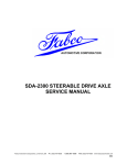
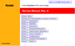
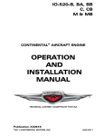
H. Lubrication Pump Disassembly
1. The lubrication pump requires no further work for
disassembly. When removed, the pump parts are
free to separate for inspection and cleaning.
2. Wear cannot be detected by feel or play. Inspect
the rotor, housing and idler for scoring. Inspect,
particularly, the drive tab of the rotor assembly. If
scoring is present, or the drive tab is notched,
replace the pump cartridge assembly.
NOTE: THE PTO-160 HAS A LARGER CAPACITY PUMP, HAVING A THICKER ROTOR
A S S E M B L Y , THICKER SPACER, AND
LONGER BOLTS. THE LARGE PUMP MAY
REPLACE THE SMALLER BY CHANGING TO
THE PTO-160 PUMP CARTRIDGE AND
SPACER, USING LONGER BOLTS. THE PTO160 PUMP SHOULD NEVER BE REPLACED
BY THE SMALL TRANSFER CASE PUMP. THE
TRANSFER CASE PUMP CARTRIDGE IS
APPROXIMATELY 1-5/8" LONG ("A" DIMENSION); THE PTO PUMP CARTRIDGE IS
APPROXIMATELY 2" LONG.
( a ) s p r i n g (c) floating plate
(d) rotor assembly (e) idler (f) i d l e r carrier (g) cover
—14—
V. CLEANING A N D INSPECTION
C. Inspection
A. Choice of Cleaning Methods
1. Steam may be used for external cleaning of
completely assembled units. Care must be taken
to ensure that water is kept out of the assembly by
tightly closing breather caps and other openings.
Prior to reassembly, parts which are to be reused
must be carefully inspected for signs of wear or
damage. Replacement of such parts can prevent
costly downtime at a future date.
2. Rough parts such as the housing, which are too
large to conveniently clean with solvents, may be
immersed in a hot solution tank containing a mild
alkaline solution. Parts cleaned in hot solution
tanks must be rinsed thoroughly to prevent
damage by traces of alkaline material.
All bearing surfaces, including roller bearing cups and
cones, should be examined for pitting, wear, or
overheating. Gears also may show pits, as well as
scoring and broken teeth. Shafts may be nicked or
marred, or may have damaged threads. Parts which
show any signs of damage should be repaired or
replaced.
3. Parts with ground or polished surfaces, such as
bearings, gears, and shafts, should be cleaned
with emulsion cleaners or petroleum solvents.
Alkaline hot solution tanks may damage the
machined surfaces and such cleaning methods
should be avoided.
Check all shift forks and slots in sliding clutches for
extreme wear or discoloration from heat. Check
engaging teeth of sliding clutches for partial engagement pattern.
B. Drying and Corrosion Inhibition
Soft clean shop towels should be used to dry parts
after cleaning. Compressed air may be used to clean
inaccessible areas of large parts such as the housing.
Bearings should not be spun dry with compressed air,
as the lack of lubrication may cause damage to the
mating surfaces.
Dried parts should be immediately coated with a light
oil or corrosion inhibitor to prevent corrosion damage.
Parts which are to be stored should also be wrapped
in heavy waxed paper.
—15—
VI. TRANSFER CASE A S S E M B L Y
B. Shaft Assembly
A. General Precautions for
Reassembly
IMPORTANT: Read this section before starting
reassembly procedure.
Make sure that the interior of the transfer case is
clean. It is important that dirt be kept out of transfer
case during reassembly. Use certain precautions, as
listed below, during reassembly.
1. Gaskets — Clean all gasket surfaces of past
gasket material. Use new gaskets throughout the
transfer case as it is being rebuilt.
2. Bolts — To prevent oil leakage, use Permatex
Form-A-Gasket #2 pliable setting sealant or
equivalent on all threaded holes drilled through
the housing. See torque specifications for recommended torque, Section VII.
3. Assembly — Refer to the views in the parts
manual as a guide to reassembly.
1. Intermediate Shaft. Heat the front bearing
cone in 350 degree oven and drop over shaft
(short journal), insuring that the bearing race bottoms against the shoulder.
4. Initial Lubrication — Coat all thrust washers,
splines and seals with lubriplate during installation to provide initial lubrication, preventing scoring and galling.
5. Bearings — Press or drive bearing races by
applying force to inner race or outer race,
whichever is being installed.
6. Universal Joint Companion Flanges - - Pull the
companion flanges tightly into place with the
Iocknuts (old Iocknuts may be used for pulling,
then replaced with new); tighten to proper torque.
If the flange is not pulled tightly into place, the
bearings will not seat properly, causing erroneous end play readings and possible damage to
bearings, shafts, and gears.
7. Inspect all spacer washers and rings for wear.
The width or thickness of each spacer washer or
ring has been noted in the assembly procedures
and each spacer should be measured with a
micrometer for proper size. Worn spacers should
be replaced.
IMPORTANT
8. Early TC & PTO-160 had a splined intermediate
shaft and gear. (See Parts Manual, Page 35, Note
@.) An intermediate design had pilot rings shrunk
onto the shaft and in the gear. Current production
has a keyed shaft and gear. Disassembly and
assembly descriptions are still the same as for
the splined shafts.
THICKWALLEDSPACER-TOP SHAFT (& BOTTOM
SHAFT W/O NEUTRAL)
—16—
THIN BEARING RACEBOTTOM SHAFT W/
NEUTRAL
2. Top and Bottom Shafts: Shafts, thrust
washers, and the thick-walled (3-3/8 in. O.D.)
spacer are identical, when the case has no
neutral shift. With the neutral shift option, the
bottom shaft will have a thin-walled (3 in. O.D.)
spacer pressed on instead of the thick-walled
one.
VI. TRANSFER CASE ASSEMBLY
B. Shaft Assembly (cont.)
C. Installation into Housing
1. Upper and lower gears are identical.
3. Install the thin (5/32 or .150 thk.) thrust washer
against the shoulder of the shaft (long journal),
with oil groove facing away from the shoulder.
Heat race (sleeve) in 350 ° oven and drop over
the shaft.
2. Place both gears in the case, lying on the bottom
of the housing side by side. Orient clutch gear
teeth toward front of case.
4. The shaft with the thick-walled sleeve will then be
the top one, while the one with the thin-walled
race will be the bottom shaft (with neutral).
3. Place intermediate gear in case, between the
upper and lower gears. Supporting the intermediate gear on the upper and lower gears, align the
gear bore with the case bore approximately,
keyway to top.
—17—
VI. TRANSFER CASE A S S E M B L Y
C. Installation into Housing (cont.)
4. Tap the key down into the keyway of the shaft.
The shaft has a small undersized starting journal
to allow starting the shaft into the gear bore, and
then align the key into the gear keyway.
5. Using a soft hammer, from the front of the case,
drive the shaft into the gear.
7. Insert front bearing cup into housing and install
gasket and front intermediate cap.
6. It is extremely helpful (and beneficial to fingers) to
insert a round bar into the pump spring hole to
assist in supporting and guiding the shaft into the
gear bore and keyway.
—18—
8. Heat the rear bearing cone to 350 ° in an oven.
Install the cone onto the rear shaft, insuring that it
is seated against the gear shoulder. Insert the
rear bearing cup and install the cap with two bolts
torqued lightly (about 15-20 lb. ft.). This holds the
rear bearing cone in place until it cools and the
shrink fit has set, insuring that the bearing race
does not move from its seat position, giving correct end play readings. The end play will be set
later.
VI. TRANSFER CASE ASSEMBLY
C. Installation into Housing (cont.)
9. Top Shaft. Install wire ring inside the clutch
collar.
11. Tilt the gear in the case so that the opening points
upward approximately in line with the housing
bearing bore.
10. Install the collar over the clutch teeth on the upper
gear with the short hub of the collar facing the
gear.
12. Insert the shaft (with the heavy wall sleeve) into
the gear bore.
—19—
VI. TRANSFER CASE A S S E M B L Y
C. Installation into Housing (cont.)
15. Install the 5/8 (.625) thick thrust washer (with oil
groove) on the rear of the shaft, oil groove facing
the gear, and support the washer in the housing
bearing bore. This will provide clearance for
bearing installation.
13. Lift the rear of the shaft, straightening the gear
and shaft assembly in relation to the case, and
support the rear of the shaft in the rear housing
bearing bore.
16. If the rear bearing and blanking sleeve (declutch
gear if PTO equipped) have been separated, a
new bearing must be installed. Heat bearing
cone to 350 ° in an oven and drop over blanking
sleeve
14. Install a clutch gear on the front shaft spline,
making sure that the end with the thick teeth goes
inside the clutch collar.
17. Install cone and sleeve assembly over rear
splines and start to drive on with a soft hammer.
—20—
VI. TRANSFER CASE ASSEMBLY
C. Installation into Housing (cont.)
20. Install rear carrier temporarily with bolts and flat
washers, torqued lightly. Install front bearing
cone loosely on shaft and insert cup, driving into
place with a soft hammer.
18. After splines are started, lift bearing up into housing bore, place a bar between the clutch gear and
the inside front of the housing to prevent the shaft
from being driven out the front, and drive the
sleeve and thrust washer into place against the
shoulder of the gear.
19. Install a thick (3/8 in.) plain washer on the front of
the shaft and support the shaft in the front bearing
bore. Install the rear bearing cup in the bore and
drive in flush with the surface of the housing.
21. Install gasket and front carrier (with seal installed), making sure that oil holes in housing and oil
grooves in carrier line up. Install bolts and flat
washers and torque to specification.
—21—-
VI. TRANSFER CASE A S S E M B L Y
C. Installation into Housing (cont.)
24. Pre-lube the needle bearings with grease.
22. Grease seal lips and start front flange onto
splines. Flange must be lifted up to start hub into
bearing bore. Drive flange on with a soft hammer
until seated. Install nut and washer and torque to
specification.
23. Bottom Shaft, With Neutral: Install needle
bearing assemblies on remaining shaft (with thinwalled bearing race). Place a bearing spacer
(approx. 3 in. O.D. x 1-1/8 Ig.) between the cages.
25. Without Neutral: Install a wire ring inside the
clutch collar, as on the top shaft (See VI. C.9,
p.19).
With Neutral: No wire ring is used. (The SSPTO
always has neutral.)
26. Install the shift collar (oriented as on the top shaft,
see VI. C.10, p.19) onto the gear clutch teeth.
27. Tilt the gear and collar in case as on the top shaft
assembly. Insert shaft and bearings through gear
bore. Lift rear end and straighten gear and shaft,
supporting shaft ends in housing bores. Install
clutch gear over splines on shaft, with thick teeth
inside the collar as on lop shaft. (See VI,
C. 14, p. 20).
—22—
VI. TRANSFER CASE ASSEMBLY
C. Installation into Housing (cont.)
28. Install the 5/8 (.625) thick thrust washer (with oil
grooves) on the rear on the shaft with oil grooves
facing the gear. Install the 3/8 (.375) thick plain
thrust washer on the front of the shaft.
30. Install bearing and gear assembly onto front of
shaft, starting the splines.
31. Lifting the shaft to allow bearing to go into bore,
push the gear against the inside of the housing at
the rear and drive the declutch gear until seated
against the washer and shaft shoulder.
29. If the bearing and declutch gear have been
separated on disassembly, a new bearing must
be installed.
—23—
VI. TRANSFER CASE A S S E M B L Y
C. Installation into Housing (cont.)
32. Insert the front bearing cup into the housing bore
and drive in flush. Install declutch housing and
bolt in place with two bolts to hold the cup while
installing output flange.
As on the top shaft, install nut and washer on the
declutch gear and torque to specification.
33. Install rear bearing cone loosely on shaft and
install cup into housing, driving in flush.
34. Install rear carrier (with seal) and gasket, aligning
oil holes and grooves, install bolts and torque to
specifications.
35. Following the same procedure as in installing the
front input flange (VI. C.22), install the rear output
flange.
36. N E U T R A L ONLY: Check the clearance
between the bottomshaft gear face and the thrust
washer. The clearance should be between .015
and .020 inch. If it is more than .020, the gear and
thrust washer should be inspected for wear and
replaced if necessary.
—24—
VI. TRANSFER CASE ASSEMBLY
D. Shimming Shafts
The top and intermediate shafts are shimmed at the
rear of the housing (PTO-160, front); the bottom shaft
is shimmed at the front (under the declutch housing).
(The PTO-160, rear.)
1. Intermediate. Bottom the bearing cup by driving the rear cap against the shaft and bearing
assembly. Measure the gap between the lip of the
cap and the housing surface with a feeler gauge,
add 3 to 8 thousandths (.003 - .008) to the
measurement and select shims to add up to this
thickness.
EXAMPLE: GAP MEASURES .164; ADDING
.003-.008 GIVES .167-.172. USE FIVE .030
SHIMS WHICH MAKE .150, PLUS ONE .015
AND ONE .005 TOTALING (.150 + .015 + .005 =)
.170, WHICH FALLS WITHIN THE RANGE.
2. Remove cap, add shims, replace cap and bolts
and torque to specification. Set a dial indicator on
front cap with contact point through the vent hole
onto the shaft end. Using a pry bar, pry the gear
back and forth, reading the indicator needle
movement. The indication should be .003 - .008
end play. If not obtained, remove cap and remove
or add shims until the proper reading is obtained.
—25—
3. Top and Bottom Shafts. The top and bottom
shafts are shimmed exactly as the intermediate
with the exception that with a PTO option, the top
shaft uses a housing at the rear instead of a
carrier to retain the bearing race, and the bottom
shaft always has a housing at the front of the
case where shimming is done. (Rear, on the
PTO-160.)
VI. TRANSFER CASE A S S E M B L Y
E. Shift Cylinder Assembly
and Adjustment (Neutral Only)
3. Install the shift fork in the shift collar. The flat side
of the fork should be toward the front of the case
(away from the shift cylinder) and the clamp bolts
should install straight into the holes. The clamp
bolt heads should be on the open side of the case
when installed, easily accessible for torqueing
and safety wiring.
4. Insert the shift shaft through the cylinder adapter,
into the fork and the rear carrier, lining the shaft
grooves up with the bolt holes. Install the shift fork
clamping screws, tighten per specification, and
install Iockwire.
5. Place the spring into the cylinder adapter over
the shaft. (The SSPTO-160 does not use the
spring.)
1. Install front adjustment cap assembly and gasket,
if removed. Lubricate the O-ring in the carrier
before insertion. Install four bolts and torque to
specification.
2. Lubricate the O-ring on the shaft cylinder adapter
and install in case.
PTO-160 — LUBRICATE THE INSIDE O-RING
AS WELL AS THE OUTER ONE.
6. Install small O-ring over the threaded stud at the
end of the shaft, install piston as shown with the
shallow groove side toward the shaft shoulder.
7. Install nut and washer, tightening to specification.
8. Place an oil-soaked felt wiper into the shallow
groove of the piston and a large O-ring into the
deep groove.
NOTE: Since it takes some time to soak the felt
wiper long enough to expand and soften enough
to fill the groove it is a good idea to do this ahead
of time. Also, the felt wiper will not necessarily fill
the groove the entire circumference of the
piston.
—26—
VI. TRANSFER CASE ASSEMBLY
E. Shift Cylinder Assembly and
Adjustment (Neutral Only) (cont.)
9. Coat the piston, O-rings and adapter with oil or
lubriplate and push the cylinder over the piston
and over the adapter. SS PTO ONLY: Install a
plastic stop ring in the cylinder between the piston and the cap.
10. Install O-ring in cylinder cap, lubricate and install
into cylinder tube end using four long cap screws.
Torque to specification, tightening evenly to
avoid cocking of the cylinder cap.
2. Slide clutch collar into the shift fork ears and
assemble the two parts together into the declutch
housing. The short hub on the collar must face
the housing and the flat side of the fork m u s t
face away from the housing. The shift fork is
not symmetrical and it is possible to install it
backward. Even if the shaft and adapter will
assemble, the fork will interfere with the inside of
the declutch housing and cause incomplete or
erratic shifting.
11. ADJUSTING THE NEUTRAL.
WITH COVER OFF: Loosen the jam nut. Apply
air to the cylinder to push the fork and collar to the
neutral position. Check for 1/8 inch of clearance
between the collar lip and the teeth on the large
gear. Adjust the bolt in or out, as needed, to obtain
the required clearance. Tighten jam nut.
WITH COVER IN PLACE: Loosen the jam nut, screw
stop bolt in until it bottoms out on the shaft end. Apply
air to the cylinder. Back off stop bolt, until the rear
output shaft turns freely without tooth clatter or noise.
Back the stop bolt off two additional full turns and lock
the jam nut. This procedure gives the 1/8 inch
clearance.
F. PTO and Declutch Assembly
1. Bolt PTO/declutch housing and gasket to main
case with six capscrews. Be sure to align oil
passages. Tighten capscrews to correct torque.
3. Install shift shaft through shift fork and into declutch housing. Align two grooves in shaft with
clamping screw holes.
4. Install two shift fork clamping screws and tighten
to correct torque. Secure clamp screws with
Iockwire.
NOTE: If the clamping screws are not easily
accessible through the side cover as shown,
the fork is installed backward.
—27—
VI. TRANSFER CASE A S S E M B L Y
F. PTO and Declutch Assembly (cont.)
necessarily fill the groove the entire circumference of the piston.
11. Coat the shift cylinder tube lightly with gear lubricant. Place cylinder tube over piston and over
adapter tube. (Use care not to cut or displace
O-rings.)
12. Install O-ring in shift cylinder cap.
13. Install cylinder cap on cylinder tube with four long
capscrews, tightening to correct torque. Tighten
capscrews evenly to prevent cocking the
cylinder cap.
14. Apply cover plate gasket to declutch housing.
15. Install cover plate with four capscrews, tightening
to correct torque.
16. Insert plunger into indicator switch hole with
rounded side of plunger against the shift shaft.
5. Install O-rings in adapter tube and insert adapter
tube into declutch housing.
17. Install indicator switch, shimming with copper
washers as necessary for proper operation.
Check with continuity indicator.
18. Press bearing cups into declutch carrier.
19. Install snap ring on output shaft and slide clutch
gear onto output shaft. Flat side of gear to face up.
6. Place small O-ring over threads of shifter shaft.
7. Place stop ring over shift shaft and place spring
over end of shift shaft.
NOTE: THERE IS NO SPRING IN THE SSPTO-160
CYLINDER.
8. Place piston over threads of shift shaft (depressing spring) with shallower of two grooves facing
towards shaft.
9. Install shift shaft nut and washer. Tighten nut to
correct torque.
10. Place an oil soaked felt wiper in shallow groove
on piston and an O-ring into deep groove.
NOTE: Since it takes some time to soak the
felt wiper long enough to expand and soften
20. Press roller bearing onto output shaft and insert
enough to fill the groove it is a good idea to do
declutch carrier onto output.
this ahead of time. Also, the felt wiper will not
—28—
VI. TRANSFER CASE ASSEMBLY
F. PTO and Declutch Assembly (cont.)
21. Place end play spacer through front of declutch
carrier and on top of inner roller bearing.
22. Press outer roller bearing onto output shaft and
into declutch carrier.
NOTE: The declutch and PTO output shaft bearings need no adjustment as the bearing spacer is
factory selected for proper end play. If the bearings, carrier, shaft or clutch gear have been
replaced, the end play should be reset, the shaft
and carrier should be assembled with the
bearings and output flange and checked with a
dial indicator as in setting the main shaft's end
play. End play should be .003 to .008 inch.
The front and rear axle outputs are identical but
use a different shaft and bearings from the PTO
outputs, whether on the TC or SSPTO, and consequently, the bearing spacers are different.
The front or rear axle output shaft will be set to
correct end play by using a .370 spacer most of
the time. Spacers are available in .005 in. increments from .360 to .385.
The PTO output shaft will use a .323 spacer most
of the time, with other thickness of .313 to .328
available.
When setting new bearings or parts, use the
above listed spacer thickness for the first
attempt, and, nearly every time, disassembly and
re-spacing will not be necessary.
25. Apply gasket to housing assembly and install
declutch carrier with eight capscrews, tightening
to correct torque. Declutch carrier must be installed so oil seal drain passage is to the bottom of
the case.
G. Oil Pump Assembly and
Installation
23. Install drive flange seal with an appropriate
driver.
24. Coat the flange hub with gear lubricant. Install
drive flange onto output shaft with nut and
Iockwasher. Tighten nut to correct torque.
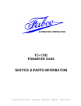
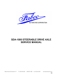
1. Measure the spring free length, A, before installing the spring in the shaft. Use this dimension to
calculate the amount of shim required.
2. Install the spring into the shaft recess, cup first
(see picture). Install pump cartridge assembly
over shaft pilot, with the drive tang in the slot.
Install the gasket, spacer and the cover. Start two
bolts in part way to guide and hold the cover and
spacer. Hold the spacer against the cap solidly,
hold the cover firmly against the spring without
compressing it and measure the unshimmed gap
between the cover and the spacer.
3. The free length of the spring, A, should be 2-1/4
to 2-9/32 inches. For proper pressure relief, the
compressed length of the spring should be 21/8 inches, and the cover-to-spacer gap must be
—29—
VI. TRANSFER CASE ASSEMBLY
G. Oil Pump Assembly and
Installation (cont.)
shimmed to make the spring this length when the
bolts are tightened down. The gap width, after
adding shims, must be the same dimension as
the difference between the free length, A, and
2-1/8 inches. After measuring the free length, A,
subtract 2-1/8. Subtract this difference from the
unshimmed gap measurement; the result is the
total required shim thickness. Divide by .030 (or
1/32) to obtain the number of shims required.
EXAMPLE:
SPRING FREE LENGTH, A = 2-9/32
UNSHIMMED GAP
= 3/16
2-9/32 MINUS 2-1/'8 (4/32) IS 5/32.
THE SPRING MUST BE COMPRESSED 5t32 TO THE PROPER DIMENSION OF 2-1 ,'8 INCHES.
3,'16 (6,.32) MINUS 5;32 = 1 /32 INCH
TOTAL SHIM THICKNESS.
EACH SHIM IS 1/32 (.030) THICK.
1/32 ÷ 1/32 = 1 SHIM
IF ANY TOTAL SHIM THICKNESS
COMES OUT WITH ONE HALF OF A
SHIM OR MORE, ADD A SHIM.
Install bolts and torque to specification.
VII. TORQUE SPECIFICATIONS
Bolt Size
*Torque
(lb.-ft.)
1/4 - 20
12
1 / 4 - 20
7/16 - 14
10
60
7/16 - 14
60
7/16 - 14
60
PTO flange retaining nut
1-1/4 - 18
400
Input, output flange & declutch
gear retaining nuts
1-1/2 - 12
600
5/16 - 18
25
Shift Shaft Piston Nut
3 / 8 - 24
30
Shift Fork Clamp Bolt
7/16 - 20
35
Location
Air shift cylinder attach bolts
Declutch housing inspection plate bolts
Declutch to case bolts
Front drive/PTO/pump carrier unit and
all end cap bolts
Access cover bolts
Pump cover bolts
*Torques given apply to parts coated with machine oil. For dry parts increase torque 10%.
—30—