1
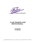
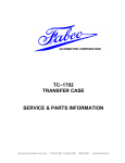
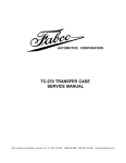
Automotive Corporation
TC–170 & TC–170 PD
TRANSFER CASE
SERVICE MANUAL
Fabco Automotive Corporation, Livermore, CA Ph:(925) 454-9500 Fax:(925) 454-9501 1-(800) 967-8838 www.fabcoautomotive.com
OPERATING INSTRUCTIONS
TC-170 Proportional Differential Transfer Case
DESCRIPTION:
The Fabco TC-170 series transfer case with proportional differential is a single-speed
unit designed for full-time all wheel drive chassis.
AIR ACTUATED TRANSFER CASE DIFFERENTIAL LOCK:
For normal operation, leave the transfer case differential control in the unlocked
position.
In poor traction conditions, the transfer case differential control may be shifted to the
locked position. The transfer case differential lock can be engaged while the chassis is
stationary, or at any speed, provided the axles are not spinning out.
CHASSIS DYNAMOMETER OPERATION:
When testing any chassis equipped with a Proportional Differential Transfer Case it is
necessary to disconnect the front driveline at the transfer case and the transfer case
differential lock must be engaged.
WARNING: The above instructions must be followed because this transfer case is not
designed for continuous operation with the rear wheels turning and the
front wheels stationary. Excessive speeding of the internal differential
parts will occur if these instructions are not observed.
TOWING:
When towing any chassis equipped with a Proportional Differential Transfer Case,
disconnect and remove both front and rear drivelines before moving chassis.
SERVICE & PARTS MANUAL
TABLE OF CONTENTS
I. LUBRICATION.................................................
4-5
Recommended Lubricants......................................
Oil Change..............................................................
Draining the Oil.......................................................
Refilling the Oil .......................................................
Inspection ...............................................................
4
4
4
4
5
II. DISASSEMBLY ............................................... . 5-15
Preliminary Steps ................................................... 5
Transfer Case Component Removal ...................... 5
Upper Shaft Removal – Models without PTO or
Hydraulic Pump Output .......................................... 6
Upper Shaft Removal – Models with PTO
Output..................................................................... 6
Upper Shaft removal – Models with
Hydraulic Pump Output .......................................... 6
Rear Output Shaft Removal ................................... 6
Front Output Shaft Removal................................... 7
Lower Shaft Removal – Models with
Proportional Differential .......................................... 7
Intermediate Shaft Removal ................................... 9
Subassemblies .......................................................10
Upper Shaft Disassembly – Models without
PTO or Hydraulic Pump Output..............................10
Upper Shaft Disassembly – Models with
PTO Output ............................................................10
Upper Shaft Disassembly – Models with
Hydraulic Pump Output ..........................................10
Intermediate Shaft Disassembly.............................10
Front Output Shaft Disassembly.............................11
Rear Output Shaft Disassembly – Models
without Neutral........................................................11
Rear Output Shaft Disassembly – Models
with Neutral.............................................................12
Lower Shaft Disassembly – Models with
33/67 Proportional Differential ................................13
Lower Shaft Disassembly – Models with
50/50 Proportional Differential ................................15
IV. ASSEMBLY ..................................................... 16-22
Assembly Precautions ........................................... 16
Subassemblies ...................................................... 16
Upper Shaft Assembly – Models without
PTO or Hydraulic Pump Output............................. 16
Upper Shaft Assembly – Models with
PTO Output ........................................................... 17
Upper Shaft Assembly – Models with
Hydraulic Pump Output ......................................... 17
Intermediate Shaft Assembly................................. 17
Front Output Shaft Assembly ................................ 17
Rear Output Shaft Assembly – Models
without Neutral....................................................... 18
Rear Output Shaft Assembly – Models
with Neutral............................................................ 19
Lower Shaft Assembly – Models with
33/67 Proportional Differential ............................... 19
Lower Shaft Assembly – Models with
50/50 Proportional Differential ...............................21
V. TRANSFER CASE
COMPONENT INSTALLATION.......................22-27
Intermediate Shaft Installation ............................... 22
Rear Output Shaft Installation ............................... 23
Lower Shaft Installation – Models with
Proportional Differential ......................................... 24
Front Output Shaft Installation............................... 25
Upper Shaft Installation – Models without
PTO or Hydraulic Pump Output............................. 26
Upper Shaft Installation – Models with
PTO Output ........................................................... 26
Upper Shaft Installation – Models with
Hydraulic Pump Output ......................................... 27
VI. TORQUE SPECIFICATIONS ................................ 28
VII. PARTS MANUAL.............................................30-57
III. CLEANING AND INSPECTION....................... 15-16
Cleaning .................................................................15
Drying and Corrosion Inhibition ..............................16
Inspection ...............................................................16
Copyright © 1989 Fabco Automotive Corporation, 1249 67th Street, Oakland, California 94662
OIL CHANGE
I. LUBRICATION
The transfer case lubricant should be changed on all new
transfer cases after the first 3,000 to 5,000 miles (onhighway), or the first 40 hours (off-highway); thereafter
oil changes should be done at the following intervals:
RECOMMENDED LUBRICANTS
On-Highway Vehicles
1. Heavy-duty Engine Oil:
On-Highway Service ................. 10,000 – 15,000 Miles
Temperature
Grade
Above + 10° F
Below + 10° F
SAE 50
SAE 30
Off-Highway Service (Logging, dirt moving, mining, and
associated operations).............. .... 500 – 750 Hours
The recommended oil change and inspection periods are
based on the average use and operating conditions that
the unit may encounter. It is suggested that the individual
owner make a periodic lab analysis of the lubricant to determine contamination based on the unit's specific operating conditions. With this data, the oil change and
inspection periods can be better determined.
Be sure to specify heavy-duty type meeting MIL-L-2104B
specifications.
2. Mineral Gear Oil:
Temperature
Grade
Above + 10° F
Below + 10° F
SAE 90
SAE 80
DRAINING THE OIL
Draining is best accomplished after the vehicle has been
operated briefly, allowing the oil to become warm and
flow more freely. Remove both drain and fill plugs. Allow
the housing to empty completely. Before the unit is refilled, it should be thoroughly flushed with clean flushing
oil or kerosene.
Must be inhibited against corrosion, oxidation, and foam.
3. MIL-L-2105B E.P. Oil, except sulfur-chlorine-lead
type:
Temperature
Grade
Above + 10° F
Below + 10° F
SAE 90
SAE 80
If the unit is equipped with an oil pump, the lube oil filter
should be replaced whenever the oil is changed. The
element is of the spin-on type. A film of clean oil should
be applied to the rubber gasket of the new element before installing. Do not over tighten.
Extreme pressure oils under some conditions might form
carbon deposits on gears, shafts, and bearings, which
will result in transfer case malfunctions and premature
failure. It is suggested that if these conditions exist, and
E.P. oil is being used, a change should be made to mineral gear oil or heavy-duty engine oil as recommended.
REFILLING THE OIL
If the transfer case has been removed from the vehicle
for service, it is best to refill the oil after the unit has been
reinstalled into the vehicle.
Off-Highway & Mining Equipment
1. Heavy-duty Engine Oil:
Temperature
Grade
Above + 10° F
Below + 10° F
SAE 50
SAE 30
Clean and replace the drain plug and fill the transfer case
with the appropriate oil with the vehicle on level ground.
Fill the transfer case to the level of the fill plug. On transfer cases equipped with a proportional differential, it may
take some time for the oil to flow into the main housing;
therefore, it is necessary to fill the unit to the level of the fill
plug, wait a few minutes, and top off the oil level. It may
be necessary to do this several times. The plug should
be installed only after the oil level has stabilized.
Be sure to specify heavy-duty type meeting MIL-L-2104B
specifications.
2. Special Recommendation: For extreme cold
weather where temperature is consistently below
0° F, use SAE 20W heavy-duty engine oil meeting
MIL-L-2104B specifications.
The approximate oil quantity is 6.5 quarts. The exact
amount will vary somewhat, depending on the model and
the inclination of the unit; therefore, always fill to the level
of the fill plug. Do not overfill. Inspect for leaks.
-4-
INSPECTION
TRANSFER CASE COMPONENT
REMOVAL
The oil is to be maintained at the level of the fill plug at all
times. Check at the following intervals:
For purposes of this manual, all basic TC-170 transfer
cases contain four shaft assemblies. Upper, Intermediate, Front Output, and Rear Output. See Figures 2 and 3.
The TC-170 PD (Proportional Differential) models contain three shaft assemblies: Upper, Intermediate, and
Lower. See Figure 4. There are various versions of each
shaft assembly, depending on the particular model transfer case being worked on. Be sure to use the correct procedure for each shaft assembly. In some procedures, a
similar procedure for a different shaft is called out.
Highway Service .................. 1,000 Miles
Off-Highway Service ................. 40 Hours
With every oil change, the shift cylinder air lines and
valves should be inspected for leaks and possible malfunctioning. Low pressure conditions can cause partial
clutch engagement which may result in premature wear
or damage.
II. DISASSEMBLY
PRELIMINARY STEPS
UPPER
SHAFT
1. After removing the transfer case for the vehicle thoroughly clean the exterior.
2. Remove the drain plug and drain the oil.
INTERMEDIATE SHAFT
ASSEMBLY
3. Mount the transfer case in a suitable fixture. The fixture should be such that the transfer case can be rotated so that either the front of the rear of the case is
facing upward. A transfer case mounted in a typical
fixture is shown in Figure 1.
FRONT OUTPUT
SHAFT
REAR OUTPUT SHAFT
ASSEMBLY
Fig 2
UPPER
SHAFT
INTERMEDIATE SHAFT
ASSEMBLY
Fig 1
4. If so equipped, remove the lubrication lines and oil filter. Note the location and routing of the lines so
that they may be correctly reinstalled.
FRONT OUTPUT SHAFT
ASSEMBLY
REAR OUTPUT SHAFT
ASSEMBLY
Fig 3
-5-
3. Remove the upper shaft assembly from the transfer
case by lifting on the shaft yoke. Discard the gasket.
UPPERT SHAFT
4. Rotate the transfer case over so that the rear end is
upward.
ASSEMBLY
INTERMEDIATE
5. Remove the (6) cap screws and washers securing
the rear cap to the transfer case housing. Remove
the cap, shim pack, and rear bearing cup. Keep the
shims together with the cap to facilitate reassembly.
SHAFT
LOWER SHAFT ASSEMBLY
(33/67 P.D.)
UPPER SHAFT REMOVAL – MODELS
WITH PTO OUTPUT
LOWER SHAFT ASSEMBLY
(50/50 P.D.)
Refer to Figures P.6 and P.15 in the parts manual.
1. Follow Steps 1 through 4 under “UPPER SHAFT
REMOVAL – MODELS WITHOUT PTO OR
HYDRAULIC PUMP OUTPUT” above
2. To remove the PTO unit, follow the similar procedure
in Steps 2 through 10 under “FRONT OUTPUT
SHAFT REMOVAL” below.
Fig 4
UPPER SHAFT REMOVAL – MODELS
WITH HYDRAULIC PUMP OUTPUT
UPPER SHAFT REMOVAL – MODELS
WITHOUT PTO OR HYDRAULIC PUMP
OUTPUT
Refer to Figures P.7 and P.15 in the parts manual
1. Follow Steps 1 through 4 under “UPPER SHAFT
REMOVAL – MODELS WITHOUT PTO OR
HYDRAULIC PUMP OUTPUT” above
Refer to Figure P.5 in the parts manual.
1. Position the transfer case with its front end
(nameplate) facing upward.
2. To remove the pump declutch unit, follow the similar
procedure in Steps 2 through 4 under “FRONT OUTPUT SHAFT REMOVAL” below.
2. Remove the (10) cap screws and washers securing
the front carrier to the transfer case housing. See
Figure 5.
3. Remove the (8) cap screws and washers securing
the hydraulic pump mounting plate and lift off the
plate and pump as an assembly.
4. Continue removing the pump declutch unit by following the similar procedure in Steps 6 through 10 under
“FRONT OUTPUT SHAFT REMOVAL” below.
REAR OUTPUT SHAFT REMOVAL
Refer to figure P.12 in the parts manual if the lower shaft
has neutral provision; Figure P.11 if not.
1. Position the transfer case with its rear end facing
upward.
2. Remove the (10) cap screws and washers securing
the rear output carrier to the transfer case housing.
See Figure 6.
Fig 5
-6-
Fig 6
Fig 8
5. Remove the (8) cap screws and washers securing
the carrier to the declutch housing.
3. Remove the carrier and shaft assembly by lifting on
the shaft yoke. Discard the gasket.
6. Lift off the shaft assembly. Discard the carrier
gasket.
FRONT OUTPUT SHAFT REMOVAL
Refer to Figures P.10 and P.15 in the parts manual.
7. Remove the air shift piston nut. Exercise caution as
the piston is spring loaded. Remove the washer,
piston, spring, and the nylon stop ring.
1. Position the transfer case with its front end facing
upward.
8. Cut and remove the safety wire on the shift fork bolts
and remove the bolts. Remove the shift shaft. It may
be necessary to carefully pry open slightly the slot in
the shift fork to free the shaft. Lift out the shift collar
and the shift fork.
2. Remove the indicator light switch and washer.
Remove the switch actuating pin with a magnet.
3. Remove the (4) cap screws securing the air shift cylinder cap. See Figure 7. Lift off the cylinder and cap.
9. Remove the (6) 12-point cap screws securing the
declutch housing to the transfer case housing. Lift
off the declutch housing and the shim pack. Keep
the shims together with the housing to facilitate reassembly. Remove the bearing cup from the transfer
case housing.
10. Do not remove the welch plug from the shift shaft
bore in the declutch housing unless necessary.
LOWER SHAFT REMOVAL – MODELS
WITH PROPORTIONAL DIFFERENTIAL
Refer to Figure P.13 in the parts manual if unit is
equipped with 33/67 proportional differential; Figure P.14
if 50/50. Refer to Figure P.15 for the air shift cylinder details.
Fig 7
1. Position the transfer case with its front end facing
upward.
4. Remove the (4) cap screws securing the declutch
housing cover plate. See Figure 8. Remove the
cover plate and discard the gasket.
2. Remove the front output yoke (or companion flange)
retaining locknut and washer. Slip off the yoke (or
flange).
-7-
3. Remove the (6) cap screws and washers that secure
the oil seal carrier to the front bearing carrier. See
Figure 9. Lift off the seal carrier and discard the
gasket.
Fig 10
13. Lift out the lower shaft assembly. See Figure 11. A
chain may be attached to the assembly by installing
two “L” brackets under two opposing differential
case half bolt heads.
Fig 9
4. Remove the (8) cap screws and washers that secure
the bearing carrier to the differential lockout housing.
Lift off the bearing carrier (including the ball bearing
assembly). Discard the gasket.
5. Remove the indicator light switch and washer.
Remove the switch actuating pin with a magnet.
6. Remove the (4) cap screws securing the air shift
cylinder cap. Lift off the cylinder and cap.
7. Remove the (4) cap screws securing the lockout
housing cover plate. Remove the cover plate and
discard the gasket.
8. Remove the air shift piston nut. Exercise caution as
the piston is spring loaded. Remove the washer,
piston, spring, and nylon stop ring.
Fig 11
9. Cut and remove the bolts. Remove the shift shaft. It
may be necessary to carefully pry open slightly the
slot in the shift fork to free the shaft. Lift out the shift
collar and the shift fork. Slide out the clutch gear.
14. Rotate the transfer case over so that its front end is
facing upward.
15. Remove the (6) 12-point cap screws securing the
differential lockout housing to the transfer case
housing. Lift off the lockout housing and the shim
pack. Keep the shims together with the housing to
facilitate reassembly. Remove the bearing cup from
the transfer case housing.
10. On models with the 50/50 proportional differential
only, lift out the front output shaft. Do not remove the
retaining ring from the shaft unless it or the shaft is to
be replaced.
11. Rotate the transfer case over so that its rear end is
facing upward.
16. Do not remove the welch plug from the shift shaft
bore in the lockout housing unless necessary.
12. Remove the (10) 12-point cap screws securing the
outer differential housing to the transfer case housing. See Figure 10. Lift off the rear output carrier and
shaft assembly and set aside. Discard the gasket.
-8-
INTERMEDIATE SHAFT REMOVAL
STEEL TUBING
6.0" O.D. x 1/4 WALL x 4.0 LONG.
If the unit is equipped with a lubrication pump, refer to
Figure P.9 in the parts manual. If not, refer to Figure P.8.
On Models not equipped with a lubrication pump, begin
the procedure at Step 4.
HEX NUT
AND WASHER.
1. Position the transfer case with its rear end facing
upward.
2. Remove the (6) cap screws and washers securing
the oil pump cap. See Figure 12. Lift off the cap,
shims, oil pump ring, and gasket. Discard the
gasket.
STEEL PLATE
3/4" THICK.
DRILLED HOLE
TO CLEAR ROD.
5/8-11 OR 3/4-16
THREADED ROD
7" LONG.
Fig 13
8. To prevent damage, do not allow the bearing cone
assembly or the gear to drop inside the case as the
shaft is being pulled out. See Figure 14. Remove
the shaft, gear, spacer, and bearing cone assembly.
Fig 12
3. Remove the oil pump cartridge and spring by lifting
from the shaft.
4. Position the transfer case with its front end facing
upward.
5. Remove the (6) cap screws and washers securing
the front intermediate cap. Remove the cap and
discard the gasket.
Fig 14
9. Rotate the transfer case over so that its rear end is
facing upward.
6. Remove the front bearing cup by pulling upwards on
the intermediate shaft assembly.
10. Remove the (6) cap screws and washers securing
the rear cap to the transfer case. Remove the cap,
shim pack, and rear bearing cup. Keep the shims
together with the cap to facilitate reassembly.
7. The gear and the rear bearing cone both have a
press fit to the intermediate shaft. Therefore, a puller
will be necessary to remove the shaft if damage is to
be avoided. A sketch depicting a suitable fabricated
puller is illustrated in Figure 13. Note that there are
two shaft designs in use. The first production version
uses a 5/8-11 threaded puller hole while later shafts
have a 3/4-16 hole. Use the appropriate size
threaded rod.
This concludes the general disassembly of the transfer
case.
-9-
4. To remove the rear bearing cone assembly, support
under the cone with a bearing separator and press
the shaft through the cone. See Figure 16. Remove
the shaft key only if necessary.
SUBASSEMBLIES
During a normal overhaul, it is neither necessary nor
desirable to completely disassemble the shaft assemblies. The bearing cone assemblies and the drive train
gears are installed with a press fit to the shaft and their
unnecessary removal only increases the likelihood of
damage. The same applies to the bearing cups installed
in the carriers.
PRESS
Parts should be cleaned with emulsion cleaners or petroleum solvents. To avoid damage, alkaline solutions
should not be used.
UPPER SHAFT DISASSEMBLY – MODELS
WITHOUT PTO OR HYDRAULIC PUMP
OUTPUT
Refer to Figure P.5 in the parts manual.
1. Remove the yoke (or companion flange) retaining
locknut with an impact wrench. Slide the yoke (or
flange) off the shaft.
Fig 16
2. Lift off the carrier assembly. Remove the oil seal
from the carrier and discard. Remove the bearing
cup from the carrier only if it is to be replaced.
UPPER SHAFT DISASSEMBLY – MODELS
WITH PTO OUTPUT
It is not necessary to disassemble the shaft assembly any further unless one or more of the components remaining are to be replaced.
Refer to Figure P.6 in the parts manual.
1. Follow the similar procedure in Steps 1 through 5
under “REAR OUTPUT SHAFT DISASSEMBLY –
MODELS WITHOUT NEUTRAL” below.
3. Place the shaft assembly in a press so that the rear
of the gear is supported and the press arbor bears
against the threaded end of the shaft. See Figure 15.
Remove the front bearing cone assembly, the
spacer washer, and the gear.
2. To disassemble the PTO output shaft assembly,
follow the similar procedure under “FRONT OUTPUT SHAFT DISASSEMBLY” below.
UPPER SHAFT DISASSEMBLY – MODELS
WITH HYDRAULIC PUMP OUTPUT
PRESS
Refer to Figure P.7 in the parts manual.
Follow the similar procedure in Steps 1 through 5 under
“REAR OUTPUT SHAFT DISASSEMBLY – MODELS
WITHOUT NEUTRAL” below.
INTERMEDIATE SHAFT DISASSEMBLY
Refer to Figure P.9 in the parts manual if unit is equipped
with a lubrication pump; if not see Figure P.8.
It is not necessary to disassemble the intermediate shaft
assembly unless a component is to be replaced.
Fig 15
1. To remove the bearing cone assembly, support
under the cone with a bearing separator and press
the shaft through the cone. See Figure 17.
- 10 -
3. Place the shaft assembly in a press such that the
face of the clutch gear is supported and the press
arbor bears against the threaded end of the shaft.
See Figure 19. Be sure that the outer diameter of the
snap ring will clear the support. Remove the carrier
assembly, the inner bearing cone assembly, the
bearing spacer ring, and the clutch gear.
PRESS
PRESS
Fig 17
2. Remove the shaft key only if necessary.
FRONT OUTPUT SHAFT DISASSEMBLY
Refer to Figure P.10 in the parts manual.
Fig 19
1. To facilitate reassembly, the end float of the shaft
should be checked prior to disassembly. Install a
dial indicator with a magnetic base as pictured in
Figure 18. Lift upward on the carrier and note the
amount of end float.
4. Remove the oil seal from the carrier and discard. Lift
out the remaining bearing cone assembly. Remove
the bearing cups from the carrier only if they are to be
replaced.
5. Remove the snap ring from the shaft only if it or the
shaft is to be replaced.
REAR OUTPUT SHAFT DISASSEMBLY –
MODELS WITHOUT NEUTRAL
Refer to Figure P.11 in the parts manual.
1. Remove the yoke (or companion flange) locknut with
an impact wrench. Slide the yoke (or flange) off the
shaft.
2. Lift off the carrier assembly. Remove the oil seal
from the carrier and discard. Remove the bearing
cup from the carrier only if it is to be replaced.
3. Remove the clutch gear retaining locknut with an
impact wrench. See Figure 20. Slide off the clutch
gear.
Fig 18
2. Remove the yoke (or companion flange) retaining
locknut with an impact wrench. Slide the yoke (or
flange) off the shaft.
- 11 -
REAR OUTPUT SHAFT DISASSEMBLY –
MODELS WITH NEUTRAL
Refer to Figure P.12 in the parts manual.
1. Remove the yoke (or companion flange) retaining
locknut with an impact wrench. Slide the yoke (or
flange) and the spacer ring off the shaft.
2. Remove the (4) cap screws securing the shift cylinder cap to the carrier. Remove the cap and the nylon
piston stop ring. Discard the cap O-ring.
3. Remove the piston retaining locknut and washer. A
wrench on the shift fork unit may be necessary to
prevent the shaft from turning. See Figure 23.
Fig 20
Steps 4 and 5 are necessary only if one or more components remaining are to be replaced.
4. Place the shaft assembly in a press so that the gear
is supported and the press arbor bears against the
yoke-end of the shaft. See Figure 21. Remove the
bearing cone assembly, the spacer washer, and the
gear. Remove the shaft key only if necessary.
PRESS
Fig 23
4. Lift the carrier assembly off the shaft and slide the
shift fork from the clutch gear.
5. Remove the piston and the nylon stop ring from the
carrier. Discard all O-rings. Remove the oil seal
from the carrier and discard.
Fig 21
6. To facilitate reassembly, the gear end float on the
shaft should be checked prior to further disassembly. Install a dial indicator with a magnetic base as
pictured in Figure 24. Lift upward on the gear and
note the amount of end float
5. To remove the remaining bearing cone assembly,
support under the cone with a bearing separator and
press the shaft through the cone. See Figure 22.
PRESS
Fig 22
Fig 24
- 12 -
7. Remove the clutch gear retaining locknut with an
impact wrench. See Figure 25. Slide the clutch gear
off the shaft.
PRESS
Fig 27
10. Do not remove the bearing cups from the gear
unless replacement is necessary since the removal
procedure may damage them or their spacer. To
remove the cups, place the gear on a work surface
with the internal clutch splines downward. With a
hammer and punch, tap at the edges of the holes in
the spacer to drive the lower cup from the gear. Turn
the gear over, remove the snap ring, and press the
remaining bearing cup from the gear.
Fig 25
8. Engage the sliding clutch gear into the larger gear
and position the assembly in a press such that the
exposed face of the clutch gear is supporting and the
press arbor bears against the opposite end of the
shaft. See Figure 26. Remove the (3) bearing cone
assemblies, the gear, the clutch gear, and the various spacers.
LOWER SHAFT DISASSEMBLY –
MODELS WITH 33/67 PROPORTIONAL
DIFFERENTIAL
PRESS
Refer to Figure P.13 in the parts manual.
1. Remove the retaining ring from the front output
shaft. See Figure 28
Fig 26
9. It is not necessary to remove the remaining bearing
cone assembly unless it is to be replaced. If so, proceed as follows. Slip the clutch gear into place on the
shaft against the spacer ring. Place the assembly in
a press such that the face of the clutch gear opposite
the ring is supported and the press arbor bears
against the end of the shaft nearest the bearing. See
Figure 27. Remove the bearing cone assembly and
the ring.
Fig 28
2. Remove the (12) bolts and separate the differential
case halves. Remove the internal gear and thrust
washer.
- 13 -
3. Remove the (6) 12-point cap screws securing the
planet carrier to the front differential case. See
Figure 29. Remove the planet carrier and sun gear
assembly from the differential case assembly. Be
careful not to lose the (2) dowel pins.
Fig 31
Perform Steps 6 and 7 only if necessary.
6. To remove the front bearing cone assembly, remove
the (8) locknuts securing the gear to the front differential case half. Place this assembly in a press such
that the gear is supported. See Figure 32. Press the
bearing cone assembly and the gear from the case.
Fig 29
4. Remove the (4) allen-head screws securing the
planet carrier cover plate to the planet carrier. See
Figure 30. Remove the cover plate and lift out the (4)
planet gears. Guide the sun gear (front output shaft)
out of the planet gear.
PRESS
Fig 32
7. Place the rear differential case half assembly in a
press such that the bearing cone is supported by a
bearing separator plate. See Figure 33. Press the
bearing cone assembly from the case.
Fig 30
PRESS
5. Remove the clutch gear retaining locknut from the
front differential case half with Fabco tool 866-0368
or equivalent. See Figure 31. Slide off the clutch
gear.
Fig 33
- 14 -
The disassembly procedure for the rear output shaft
assembly follows.
PRESS
8. Remove the (10) cap screws and washers fastening
the rear carrier to the outer differential housing. See
figure 34. Separate the carrier from the housing.
Discard the gasket.
FABRICATED TUBE:
4.5" OD x 3.375 ID.
Fig 36
12. Remove the oil seal from the carrier and discard. Lift
out the remaining bearing cone assembly. Remove
the bearing cups from the carrier only if they are to be
replaced.
LOWER SHAFT DISASSEMBLY –
MODELS WITH 50/50 PROPORTIONAL
DIFFERENTIAL
Fig 34
9. To facilitate reassembly, the end float of the rear output shaft should be checked prior to further disassembly. Install a dial indicator with a magnetic base
as pictured in Figure 35. Lift upward on the carrier
and note the amount of end float.
Refer to Figure P.14 in the parts manual.
1. Remove the (12) bolts and separate the differential
case halves. Lift out the differential spider cross
including the (4) pinion gears and their thrust washers. Remove the (2) side gears and thrust washers
from the differential case halves.
Remove the bearing cone assemblies from the differential case halves only if replacing them. Refer to Steps 6
and 7 under “LOWER SHAFT DISASSEMBLY – MODELS WITH 33/67 PROPORTIONAL DIFFERENTIAL”
above.
2. Refer to Steps 8 through 12 under “LOWER SHAFT
DISASSEMBLY – MODELS WITH 33/67 PROPORTIONAL DIFFERENTIAL” above for disassembly of
the rear output shaft assembly.
III. CLEANING AND INSPECTION
Fig 35
10. Remove the yoke (or companion flange) locknut with
an impact wrench and slide the yoke (or flange) off
the shaft.
CLEANING
Steam may be used for external cleaning of completely
assembled units. Care must be taken to ensure that
water is kept out of the assembly by sealing breather
caps and other openings.
11. Place the assembly in a press as depicted in Figure
36. Note that a fabricated spacer tube is required.
Press the shaft through and remove the inner bearing cone assembly, the spacer washer, and the
carrier assembly from the shaft.
- 15 -
2. All parts must be clean. The gasket surfaces must
be free of old gasket material.
The transfer case housing, which is too large to conveniently clean with solvents, may be immersed in a hot solution tank containing a mild alkaline solution. Aluminum
parts such as the carriers, caps, declutch housing, and
air shift cylinder components must never be cleaned in
any type of alkaline solution. Parts cleaned in a hot solution tank must be rinsed thoroughly to prevent damage by
traces of alkaline material.
3. Bearing cup bores, shaft spline, and bearing mounting surfaces. should be coated with Lubriplate or
equivalent. This is necessary to reduce the possibility of galling.
4. The oil seals should be coated with Loctite 601 or
equivalent on their outer diameter prior to being installed in their bores. Their sealing lips should be
coated with Lubriplate or equivalent to provide initial
lubrication.
Parts with ground or polished surfaces, such as bearings,
gears, shafts, and oil pump components should be
cleaned with emulsion cleaners or petroleum solvents.
An alkaline solution may damage the machined surfaces
and such cleaning methods should be avoided
5. Any external cap screw not to be installed in a blind
hole should have its threads coated with Permatex
Form-A-Gasket #2 or equivalent non-hardening
sealer to prevent an oil leak.
DRYING AND CORROSION INHIBITION
Dry compressed air or clean, soft shop towels should be
used to dry parts after cleaning. Bearings should never
be spun dry with compressed air.
6. All threaded fasteners should be tightened to the
torque specified in the torque chart.
Dried parts should be immediately coated with a light oil
or corrosion inhibitor to prevent corrosion damage. Parts
which are to be stored should also be wrapped in heavy
waxed paper and kept dust-free.
7. Universal joint yokes or companion flanges should
be coated with Lubriplate or equivalent on their seal
operating area before installation. They should be
tightened into place with their locknuts tightened to
the proper torque before the shim thickness is determined.
INSPECTION
Prior to reassembly, parts which are to be reused must be
carefully inspected for signs of wear or damage. Replacement of such parts can prevent costly downtime at a
future date.
8. In many of the procedures, when a part is assembled
with a press fit, it is recommended that the part be
heated prior to installation. The part should be
placed in an oven and heated to no more than 300°
F. Excessive heat may change the metallurgical
properties of the part. Heated components should
be allowed to cool to room temperature before
end float measurements are made.
All bearing surfaces, including roller bearing cups and
cones, should be examined for pitting, wear, or overheating. Gears also may show pits, as well as scoring and
broken teeth. Shafts may be nicked or marred, or may
have damaged threads. Parts which show any sign of
damage should be repaired or replaced.
SUBASSEMBLIES
Inspect the rotor, housing, and idler of the oil pump (if
equipped) for scoring. Inspect the drive tab of the rotor
assembly. If any damage is noted, the pump cartridge
assembly should be replaced as a unit.
In the assembly procedures that follow, it is assumed that
the shaft assembly was completely disassembled. Skip
any step that refers to a part that is already assembled.
Check all shift forks and slots in sliding clutches for wear
or discoloration due to heat. Check the engaging teeth
for a partial engagement wear pattern.
UPPER SHAFT ASSEMBLY – MODELS
WITHOUT PTO OR HYDRAULIC
PUMP OUTPUT
Refer to Figure P.5 in the parts manual.
IV. ASSEMBLY
1. Install the shaft key.
ASSEMBLY PRECAUTIONS
2. Heat and install the bearing cone assembly against
the shoulder on the non-threaded end of the shaft.
See Figure 37.
1. Read the instructions completely before starting reassembly. Refer to the appropriate exploded view in
the parts manual.
- 16 -
INTERMEDIATE SHAFT ASSEMBLY
Refer to Figure P.9 in the parts manual if unit is equipped
with a lubrication pump; if not see Figure P.8.
1. Install the shaft key.
2. Heat and install the bearing cone assembly on the
end of the shaft closest the the shoulder. See Figure
38.
Fig 37
3. Heat and install the gear on the other end of the shaft
against the shoulder. slip the spacer washer against
the gear. Heat and install the remaining bearing
cone assembly on the shaft against the washer.
4. Press the front bearing cup into the carrier and install
a new oil seal.
5. Place the carrier into position and slide the yoke (or
companion flange) onto the shaft. Install the yoke
retaining locknut. For convenience, the nut may be
torqued after the shaft assembly has been installed
in the transfer case housing.
Fig 38
The remainder of the intermediate shaft assembly must
be done inside of the transfer case housing during the
shaft installation procedure.
UPPER SHAFT ASSEMBLY – MODELS
WITH PTO OUTPUT
FRONT OUTPUT SHAFT ASSEMBLY
Refer to Figure P.10 in the parts manual.
Refer to Figure P.6 in the parts manual.
1. Install the snap ring on the shaft.
1. Follow the similar procedure in Steps 1 through 5
under “REAR OUTPUT SHAFT ASSEMBLY –
MODELS WITHOUT NEUTRAL” below.
2. Slide the clutch gear over the shaft such that the
counterbore in the gear fits over the snap ring. See
Figure 39.
2. To assemble the PTO output shaft assembly, follow
the similar procedure under “FRONT OUTPUT
SHAFT ASSEMBLY” below.
UPPER SHAFT ASSEMBLY – MODELS
WITH HYDRAULIC PUMP OUTPUT
Refer to Figure P.7 in the parts manual.
Follow the similar procedure in Steps 1 through 5 under
'REAR OUTPUT SHAFT ASSEMBLY – MODELS WITHOUT NEUTRAL" below.
Fig 39
- 17 -
6. After a shaft end float within specification is obtained,
remove the yoke (or companion flange) and install a
new oil seal. Reinstall the yoke (or flange) and its
locknut. Torque to specification.
3. Heat and install the bearing cone assembly against
the clutch gear. Slide the bearing spacer ring
against the bearing cone assembly.
The bearing cone spacer ring is a select-fit part that
is used to adjust the shaft end float. If the end float
checked prior to disassembly was within specification (.003 to .008 in.) and no parts were replaced, the
original bearing spacer ring should provide the correct end float on reassembly.
REAR OUTPUT SHAFT ASSEMBLY –
MODELS WITHOUT NEUTRAL
Refer to Figure P.11 in the parts manual.
1. Install the shaft key.
4. Press the bearing cups into the carrier and place the
carrier assembly into position. Heat and install the
remaining bearing cone assembly. See Figure 40.
Do not install the oil seal at this time. Slide the yoke
(or companion flange) onto the shaft. Install and
torque the locknut.
2. Heat and install the bearing cone assembly on the
end of the shaft closest to the shoulder. See
Figure 42.
Fig 42
3. Heat and install the gear on the other end of the shaft.
See Figure 43. Slip the spacer washer against the
gear. Heat and install the remaining bearing cone assembly on the shaft against the washer. Slide the
clutch gear into place against the other cone and install the clutch gear retaining locknut. For convenience, the nut may be torqued after the shaft
assembly has been installed in the transfer case
housing.
Fig 40
5. Install a dial indicator as depicted in Figure 41. Lift
upward on the carrier assembly and note the shaft
end float on the dial indicator. If the end float is not
within specification (.003 to .008 in.), it will be necessary to disassemble the shaft following Steps 2 and 3
under “FRONT OUTPUT SHAFT DISASSEMBLY”
above. Measure the thickness of the original spacer
ring and select a new ring to provide end float within
specification. See Item 7 on P.10 in the parts manual
for a list of available spacer rings. Be sure to recheck
the shaft end float after the new spacer ring is installed.
Fig 43
4. Press the front bearing cap into the carrier and install
a new oil seal.
Fig 41
- 18 -
5. Place the carrier into position and slide the yoke (or
companion flange) onto the shaft. Install the locknut.
For convenience, the nut may be torqued after the
shaft assembly has been installed in the transfer
case housing.
REAR OUTPUT SHAFT ASSEMBLY –
MODELS WITH NEUTRAL
Refer to Figure P.12 in the parts manual
1. Slide the thin washer (Item #12, Figure P.12) on the
end of the shaft with the 21-tooth spline. Heat and
install a gear bearing cone assembly (one of the narrower two) against the washer. Slide the bearing
spacer ring against the cone.
Fig 44
6. Slide the clutch collar into engagement with the gear
internal splines. Slip the inner ring (Item #15, Figure
P.12) into position against the splines closest the
middle of the shaft. Heat and install the remaining
bearing cone assembly against the ring. Slip the
outer ring (Item #18, Figure P.12) into position
against the bearing cone.
Note that the bearing spacer ring is a select-fit part
that is used to adjust the gear end float. If the end
float checked prior to disassembly was within specification (.003 to .008 in.) and no parts were replaced,
the original bearing spacer ring should provide the
correct end float on reassembly.
2. Install the snap ring in the groove of the gear. Press a
bearing cup into the end of the gear nearest the snap
ring. Note that the cup has a light press fit to the
gear. The cup should be snug against the snap ring.
Insert the bearing cup spacer from the other end.
Press in the remaining bearing cup snug against the
spacer. Position the gear assembly onto the shaft.
The face of the gear with the internal clutch splines
must go toward the shaft shoulder.
7. Press the bearing cup into the carrier and install a
new oil seal. Install a new shifter shaft O-ring into its
groove in the carrier.
8. Assemble the shifter shaft to the shift fork and install
the locknut and washer. Slip the shift fork into the
groove in the clutch collar and place the carrier assembly into position over both shafts.
9. Install the piston-to-shaft O-ring over the threaded
portion of the shifter shaft. Insert one of the nylon
piston stop rings into the cylinder bore.
3. Heat and install the remaining gear bearing cone
assembly. Slide the spacer ring (Item #5, Figure
P.12) over the shaft against the bearing cone.
10. Install the piston O-ring in the deeper groove in the
piston. Soak the air shift piston felt strip in gear oil
and install in the other groove. Insert the piston into
its bore. The end of the piston with the felt strip must
go in first. Install the shifter shaft washer and nut
over the piston. Insert the remaining nylon piston
stop ring into the cylinder bore.
4. Heat and install the shaft bearing cone assembly
against the spacer ring. Slip the clutch gear into
place against the bearing cone. Install and torque
the clutch gear retaining locknut to specification. For
convenience, the clutch collar may be engaged with
the internal splines of the gear to lock the shaft to the
gear.
11. Install a new O-ring on the shift cylinder cap. Install
the cap and torque the (4) cap screws.
5. Install a dial indicator as depicted in Figure 44. Lift
upward on the gear assembly and note the gear end
float on the dial indicator. If the end float is not within
specification (.003 to .008 in.) it will be necessary to
disassemble the shaft by performing Steps 7 and 8
under “REAR OUTPUT SHAFT DISASSEMBLY –
MODELS WITH NEUTRAL”. Measure the thickness
of the original spacer ring and select a new ring to
provide end float within specification. See item 11 on
P.12 in the parts manual for a list of available spacer
rings. Be sure to recheck the gear end float after a
new spacer ring is installed.
12. Slide the yoke (or companion flange) onto the shaft
and install the locknut for convenience, the nut may
be torqued after the shaft assembly has been
installed in the transfer case housing.
LOWER SHAFT ASSEMBLY – MODELS
WITH 33/67 PROPORTIONAL DIFFERENTIAL
Refer to Figure P.13 in the parts manual.
1. Heat the rear bearing cone assembly and install on
the rear differential case half.
- 19 -
6. Install the internal gear over the planet gears and
place the thrust washer on the gear. See Figure 47.
2. Place the large gear into position on the front differential case half. It may be desirable to heat the gear
slightly. Allow the gear to cool completely, and install
the (8) gear retaining lock nuts. Torque to specification. Heat and install the front bearing cone assembly against the shoulder on the case.
3. slide the clutch gear into place against the bearing
cone. Install the clutch gear retaining locknut using
Fabco Tool 866-0368 or equivalent. See Figure 45.
Torque to specification.
Fig 47
7. Assemble the two differential case halves together
and install the (12) bolts. Torque to specification.
8. Install the retaining ring on the front output shaft.
See Figure 48.
Fig 45
4. Guide the sun gear (front output shaft) into the planet
gear carrier. Place the (4) planet gears into position
in the carrier. The chamfered face of the cover
should face away from the carrier. Install the (4)
allen-head shoulder screws and torque to specification.
5. Make sure that the two dowel pins are in place inside
the front differential case. Guide the planet carrier
assembly into the front differential case assembly
engaging the dowel pins. See Figure 46. Note that it
is critical to the operation of the differential assembly
that there be no nicks, burrs, or foreign matter
between the two assemblies which would interfere
with the proper seating of the carrier. Install the (6)
12-point cap screws to secure the planet carrier
assembly in place. Tighten a crisscross pattern and
torque to specification.
Fig 48
The assembly procedure for the rear output shaft assembly follows.
9. Press the bearing cups into the carrier.
10. Heat one of the bearing cone assemblies and install
on the rear output shaft against the shoulder. Slide
the bearing spacer ring against the bearing cone.
The bearing spacer ring is a select-fit part that is used to
adjust the shaft end float. If the end float check prior to
disassembly was within specification (.003 to .008 in)
and no parts were replaced, the original ring should provide the correct end float on reassembly.
11. Place the carrier assembly into position. Heat and
install the remaining bearing cone assembly. Do not
install the oil seal at this time.
12. Slip the yoke (or companion flange) into place. Install the locknut and torque to specification.
Fig 46
- 20 -
13. Install a dial indicator with a magnetic base as
depicted in Figure 49. Lift upward on the carrier
assembly and not the shaft end float on the dial indicator. If the end float is not within specification (.003
to .008 in.), it will be necessary to disassemble the
shaft by performing Steps 10 and 11 under “LOWER
SHAFT DISASSEMBLY – MODELS WITH 33/67
PROPORTIONAL DIFFERENTIAL”. Measure the
thickness of the original spacer ring and select a new
ring to provide end float within specification. See
Item 41 on P.13 in the parts manual for a list of available spacer rings. Be sure to check the shaft end
float after a new spacer ring is installed.
Fig 50
4. Place a thrust washer onto one of the differential
side gears and insert into the front differential carrier
half. See Figure 51.
Fig 49
14. After a shaft end float within specification is
obtained. remove the yoke (or companion flange)
and install a new oil seal. Reinstall the yoke (or
flange) and its locknut. Torque to specification.
Fig 51
5. Assemble the (4) differential pinion gears and their
thrust washers onto the differential spider cross and
place into the front differential case half. See Figure
52
15. Install the carrier assembly to the outer differential
housing using a new gasket. Note that the flush face
of the housing fits against the carrier. Install the (10)
cap screws and washers. Torque to specification.
LOWER SHAFT ASSEMBLY – MODELS
WITH 50/50 PROPORTIONAL DIFFERENTIAL
Refer to Figure P.14 in the parts manual.
1. heat the rear bearing cone assembly and install on
the rear differential case half.
2. Place the large gear into position on the front differential case half. It may be desirable to heat the gear
slightly. Allow the gear to cool completely and install
the (8) gear retaining locknuts. Torque to specification. Heat and install the front bearing cone assembly against the shoulder of the case.
Fig 52
6. Place a thrust washer onto the remaining side gear
and place into position against the pinion gears.
Assemble the two differential case halves together.
Install the (12) bolts and torque to specification.
3. slide the clutch gear into place against the bearing
cone. Install the clutch gear retaining locknut using
Fabco Tool 866-0368 or equivalent. See Figure 50.
Torque to specification.
- 21 -
7. To assemble the rear output shaft assembly, follow
Steps 9 through 14 under “LOWER SHAFT ASSEMBLY – MODELS WITH 33/67 PROPORTIONAL
DIFFERENTIAL” above.
V. TRANSFER CASE COMPONENT
INSTALLATION
INTERMEDIATE SHAFT INSTALLATION
If the unit is equipped with a lubrication pump, refer to
Figure P.9 in the parts manual. If not, refer to Figure P.8.
1. Position the transfer case with its front end (nameplate) facing upward.
Fig 54
6. Place the bearing cup into its bore. Install the rear
cap with the original shim pack. Install the (6) cap
screws and washers. Torque to specification.
2. Heat the intermediate shaft gear and lower it into the
transfer case housing through the upper shaft bore.
Position the gear against the rear of the housing in
line with the intermediate shaft bores. See Figure
53. Quickly lower the intermediate shaft assembly
through the gear. Be sure that the gear is firmly
seated against the shaft shoulder.
7. If the unit is equipped with a lubrication pump, mount
a dial indicator such that the indicator tip rests
against the end of the shaft. See Figure 55.
Fig 55
If the unit has a solid cap (no lubrication pump), the dial
indicator should be mounted so that its tip rests against
the rear face of the intermediate shaft gear. See Figure
56.
Fig 53
3. Place one of the bearing cups into its bore in the front
of the housing. Install the front intermediate shaft
cap with a new gasket. Install the (6) cap screws and
washers. Torque to specification.
4. Rotate the transfer case over so that its rear end is
facing upward. To prevent damage, reach in the
case and support the intermediate shaft assembly
as the unit is rotated.
5. Slip the spacer washer over the intermediate shaft
against the gear. Heat and install the remaining
bearing cone assembly against the spacer washer.
See Figure 54.
Fig 56
- 22 -
Pry the gear up and down several times to be sure that
the bearing cups are seated. Note the indicated shaft
end float on the dial indicator. If the end float is not within
specification (.003 to .008 in.), the shim pack should be
removed and replaced with a combination of shims which
will provide the proper end float. See Item 10 on P.8 in
the parts manual for a list of available shims. Be sure to
recheck the end float afterwards.
FRONT DECLUTCH
HOUSING
If the unit is not equipped with a lubrication pump, the
intermediate shaft installation is complete. The steps
that follow are only for units with a lubrication pump.
8. Insert the oil pump spring into the shaft counterbore.
Be sure to insert the end of the spring with the long
metal shell into the shaft first.
Fig 57
4. Rotate the transfers case over so that its rear end is
facing upward.
9. Assemble the pump cartridge (Item 13) as shown in
Figure P.9 in the parts manual. Install the cartridge
over the intermediate shaft such that the tang of the
cartridge shell engages with the slot in the shaft.
5. Make sure that the front bearing cup is still in place.
Position a new gasket on the transfers case housing
and lower the rear output shaft assembly into place.
The work “TOP” on the carrier must be toward the
top of the transfer case as installed in the vehicle.
Install the (10) cap screws and washers to secure
the carrier to the transfer case housing. Torque to
specification.
10. Place the oil pump ring into position over a new
gasket.
11. The amount that the oil pump spring is compressed
is set by the number of shims used between the
pump cap and ring. The correct amount of spring
compression is between .040 and .080 inches.
6. If not done so already, torque both the yoke (or
flange) and the clutch gear retaining locknuts.
Measure the gap between the pump cap and ring as the
cap is held against the cartridge lightly so as not to compress the spring. Subtract .060 from this measurement
and choose the number of shims that will come closest to
this figure. Note that each shim is .031 inches thick.
7. Mount a dial indicator on the shaft as shown in
Figure 58. Pry the rear output shaft up and down
several times to be sure that the front bearing cup is
seated. Note the indicated shaft end float on the dial
indicator. If the end float is not within specification
(.003 to .008 in.), the shim pack should be removed
and replaced with a combination of shims which will
provide the specified end float. See Item 16 on P.10
in the parts manual for a list of available shims. Be
sure to recheck the end float afterwards.
Place the correct number of shims over the ring and
install the pump cap. Make sure that the shaft is positioned so that the pin protruding from the cap fits into the
semicircular depression in the end of the pump cartridge.
Install the (6) cap screws and washers. Torque to specification.
REAR OUTPUT SHAFT INSTALLATION
Refer to Figure P.12 if the unit has provisions for neutral,
Figure P.11 if not. See Figure P.10 also.
1. Position the transfer case with its front end (nameplate) facing upward.
2. If removed, install the expansion plug into the shifter
shaft bore of the front declutch housing. Use nonhardening sealer to prevent an oil leak.
3. Insert the front bearing cup into its bore. Using the
original shim pack, position the front declutch housing on the transfer case such that the shifter shaft
bores are directly to the left of the lower shaft bore
(as viewed when the unit is installed in the vehicle).
See Figure 57. Install the (6) 12-point cap screws
and torque to specification.
Fig 58
- 23 -
6. Lower the rear output shaft assembly into position
with a new gasket. The work “TOP” on the rear carrier must be toward the top of the transfer case as installed in the vehicle. Torque the (10) 12-point cap
screws to specification.
LOWER SHAFT INSTALLATION – MODELS
WITH PROPORTIONAL DIFFERENTIAL
Refer to Figure P.13 in the parts manual if unit is
equipped with a 33/67 proportional differential, Figure
P.14 if 50/50. Refer to Figure P.15 for the air shift cylinder
details.
7. Rotate the transfer case over so that its front end is
facing upward.
1. Position the transfer case with its front end (nameplate) facing upward.
8. Install a dial indicator such that the indicator tip rests
against the end of the clutch gear as shown in Figure
61. Pry the lower shaft assembly up and down several times to be sure that the front bearing cup is
seated. The prying must be done on the clutch gear,
not at the rear output shaft. Note the indicated shaft
end float. If the end float is not within specification
(.003 to .008 in.), the shim pack should be removed
and replaced with a combination of shims which will
provide the specified end float. See Item 16 on P.13
or 14 in the parts manual for a list of available shims.
Be sure to recheck the end float afterwards.
2. If removed, install the expansion plug into the shifter
shaft bore of the differential lockout housing. Use
non-hardening sealer to prevent an oil leak.
3. Insert the front bearing cup into its bore. Using the
original shim pack, position the P.D. lockout housing
on the transfer case such that the shifter shaft bores
are directly to the left of the lower shaft bore (as
viewed when the unit is installed in the vehicle). See
Figure 59. Install the (6) 12-point cap screws and
torque to specification.
P.D. LOCKOUT
HOUSING
Fig 61
Fig 59
9. On models with the 50/50 proportional differential
only. Insert the front output shaft.
4. Rotate the transfer case over so that its rear end is
facing upward.
10. To install the air shift cylinder parts, follow the similar
procedure in Steps 2 through 9 under “FRONT OUTPUT SHAFT INSTALLATION” below.
5. Make sure that the front bearing cup is still in place.
Lower the lower shaft assembly into place. See
Figure 60.
Fig 62
Fig 60
- 24 -
4. Install two new O-rings on the shift cylinder adapter
tube and push into the front declutch housing. The
end of the tube with the counterbore must face outward.
11. Install the front bearing carrier using a new gasket.
See Figure 62. Be sure that the work “TOP” is toward the top of the transfer case as installed in the
vehicle. Install the (8) cap screws and washers and
torque to specification.
5. Install a new piston-to-shaft O-ring over the
threaded portion of the shaft. Slide the spring over
the shaft. Place the nylon stop ring over the shaft
and spring.
12. slip the ball bearing assembly into position with the
snap ring end outward. Tap gently on its outer race if
necessary.
6. Install a new piston O-ring in the deeper groove in
the piston. Soak the air shift piston felt strip in gear
oil and install in the other groove. Position the piston
on the shifter shaft. The end of the piston with the
counterbore should be facing outward. Push the piston down to compress the spring and install the
shifter shaft washer and locknut. Torque the nut to
specification.
13. Install a new oil seal into the seal carrier and install to
the bearing carrier using a new gasket. The two slots
in the rear face of the seal carrier must lineup with the
two non-tapered holes in the bearing carrier.
14. Install the front output yoke (or companion flange)
and its retaining washer and locknut. Torque to
specification.
FRONT OUTPUT SHAFT INSTALLATION
7. Install the declutch housing cover with a new gasket.
See Figure 64. Torque the (4) cap screws to specification.
Refer to Figures P.10 and P.15 in the parts manual
1. Position the transfer case with its front end upward.
The front declutch housing should already be installed. The front declutch housing should already
be installed. See “REAR OUTPUT SHAFT INSTALLATION” above.
2. Slide the shift fork onto the clutch collar and place the
two parts as a unit into the declutch housing. The
clutch collar must be installed in the direction as indicated in Figure P.10 in the parts manual. See Figure
63.
3. Insert the shift shaft into position. Rotate the shaft so
that the slots lineup with the bolt holes in the shift
fork. Install the two shift fork bolts and torque to
specification. Install the lock wire between the two
bolt heads. See Figure 63.
Fig 64
8. Slip the air shift cylinder into position over the piston.
Install a new O-ring on the shift cylinder cap and insert into the cylinder. Secure the assembly with the
(4) long cap screws. Torque to specification.
9. Insert the indicator switch actuating pin into place.
The rounded end of the pin must face inward. Install
the switch using a new copper washer. Torque to
specification.
10. Using a new gasket, install the front output shaft assembly to the declutch housing. See Figure 65. The
oil drain-back passage in the carrier must be toward
the bottom of the transfer case as installed in the vehicle. Install the (8) cap screws and washers and
torque to specification.
Fig 63
- 25 -
Fig 65
Fig 66
UPPER SHAFT INSTALLATION –
MODELS WITHOUT PTO OR HYDRAULIC
PUMP OUTPUT
UPPER SHAFT INSTALLATION –
MODELS WITH PTO OUTPUT
Refer to Figure P.6 and P.15 in the parts manual.
Refer to Figure P.5 in the parts manual.
1. Position the transfer case with its rear end facing upward.
1. Position the transfer case with its rear end facing upward.
2. If removed install the expansion plug into the shifter
shaft bore of the declutch housing. Use nonhardening sealer to prevent an oil leak.
2. Insert the rear bearing cup into its bore. Using the
original shim pack, install the rear cap to the transfer
case housing. The two slots in the carrier must
lineup with the two non-tapped holes in the housing.
Secure with the (6) cap screws and washers.
Torque to specification.
3. Insert the rear bearing cup into its bore. Using the
original shim pack, position the PTO declutch housing on the transfer case such that the shifter shaft
bores are directly to the left of the upper shaft bore
(as viewed when the unit is installed in the vehicle).
See Figure 67. Install the (6) 12-point cap screws
and torque to specification.
3. Rotate the transfer case over so that its front end is
facing upward.
4. Make sure that the rear bearing cup is still in place.
Position a new gasket on the transfer case housing
and lower the upper shaft assembly into place. The
work “TOP” on the carrier must be toward the top of
the transfer case as installed in the vehicle. Install
the (10) cap screws and washers. Torque to specification.
PTO DECLUTCH
HOUSING
5. Mount a dial indicator on the shaft as shown in Figure
66. Pry the shaft up and down several times to be
sure that the rear bearing cup is seated. Note the indicated shaft end float on the dial indicator. If the end
float is not within specification (.003 to. 008 in.), the
shim pack should be removed and replaced with a
combination of shims which will provide the specified
end float. See item 13 on P.5 in the parts manual for
a list of available shims. Be sure to recheck the end
float afterwards.
Fig 67
4. Follow the similar procedure in Steps 3 through 5 under “UPPER SHAFT INSTALLATION – MODELS
WITHOUT PTO OR HYDRAULIC PUMP OUTPUT”
above.
- 26 -
5. To install the PTO shaft and air shift components,
follow the similar procedure in Steps 2 through 10
under “FRONT OUTPUT SHAFT INSTALLATION”
above.
8. Place a new gasket on the declutch housing and assemble to hydraulic pump and mounting plate assembly to the declutch housing. The lubrication
fitting hole in the pump mounting plate should be toward the top of the transfer case as installed in the
vehicle. Install the (8) cap screws and washers.
Torque to specification.
UPPER SHAFT INSTALLATION – MODELS
WITH HYDRAULIC PUMP OUTPUT
Refer to Figures P.7 and P.15 in the parts manual.
1. Position the transfer case with its rear end upward.
2. If removed, install the expansion plug into the shifter
shaft bore of the declutch housing. use nonhardening sealer to prevent an oil leak.
NOTES
3. Insert the rear bearing cup into its bore. Using the
original shim pack, position the PTO declutch housing on the transfer case such that the shifter shaft
bores are directly to the left of the upper shaft bore
(as viewed when the unit is installed in the vehicle).
See Figure 67 above. Install the (6) 12-point cap
screws and torque to specification.
4. Follow the similar procedure in Steps 3 through 5 under “UPPER SHAFT INSTALLATION – MODELS
WITHOUT PTO OR HYDRAULIC PUMP OUTPUT”
above.
5. To install the air shift components, follow the similar
procedure in Steps 2 through 9 under “FRONT OUTPUT SHAFT INSTALLATION” above.
6. Mount the hydraulic pump to the pump mounting
plate. Note that the lubrication fitting hole in the plate
must be on top when mounted to the transfer case as
installed in the vehicle. To prevent an oil leak, use a
thin film of anaerobic sealing compound (Loctite 504
“Gasket Eliminator” or equivalent) between the
pump and the plate. Tighten the (4) mounting bolt
nuts to specification.
7. Install the pump drive gear on the pump shaft. See
Figure 68 for correct positioning. Tighten the two set
screws to specification.
HYDRAULIC
PUMP
2.87"
2.92
PUMP MOUNTING
PLATE
Fig 68
- 27 -
VI. TORQUE SPECIFICATIONS
DESCRIPTION
SIZE
TORQUE
(LB-FT)
A. Upper Shaft
Front Carrier to Housing .........................................................................................
Rear Cap to Housing ..............................................................................................
Declutch Housing to Main Housing.........................................................................
PTO Carrier to Declutch Housing ...........................................................................
Cover Plate to Declutch Housing............................................................................
Hydraulic Pump Mounting Plate to Declutch Housing ............................................
Hydraulic Pump to Mounting Plate Locknut............................................................
Front Yoke/Flange Retaining Locknut ....................................................................
Clutch Gear Retaining Locknut...............................................................................
PTO Yoke/Flange Retaining Locknut .....................................................................
Hydraulic Pump Drive Gear Set Screws.................................................................
7/16-14
7/16-14
7/16-14
7/16-14
1/4-20
7/16-14
1/2-13
1 3/4-12
1 3/4-12
1 1/2-12
3/8-16
......................45
......................45
......................20
......................35
........................7
......................35
......................60
....................600
....................600
....................500
......................50
B. Intermediate shaft
Front/Rear Cap ....................................................................................................... 7/16-14 ......................45
Oil Pump Cap ......................................................................................................... 5/16-24 ......................15
C. Front Output Shaft
Declutch Housing to Main Housing......................................................................... 7/16-14 ......................20
Carrier to Declutch Housing.................................................................................... 7/16-14 ......................35
Cover Plate to Declutch Housing............................................................................ 1/4-20 ........................7
Yoke/Flange Retaining Locknut.............................................................................. 1 3/4-12 ....................600
D. Rear Output Shaft
Rear Carrier ............................................................................................................ 7/16-14 ......................45
Shift Cylinder Cap................................................................................................... 1/4-20 ......................15
Clutch Gear Retaining Locknut............................................................................... 1 3/4-12 ....................600
Yoke/Flange Retaining Locknut.............................................................................. 1 3/4-12 ....................600
Shift Fork to Shaft Locknut ..................................................................................... 1/2-20 ......................60
Air Shift Piston to Shaft........................................................................................... 3/8-24 ......................25
E. Lower shaft (Proportional Differential)
Lockout Housing to Main Housing ..........................................................................
Bearing Carrier to Lockout Housing........................................................................
Seal Carrier to Bearing Carrier ...............................................................................
Cover Plate to Declutch Housing............................................................................
Rear Carrier to P.D. Housing..................................................................................
P.D. Housing to Main Housing................................................................................
Front Yoke/Flange Retaining Locknut ....................................................................
Rear Yoke/Flange Retaining Locknut .....................................................................
Clutch Gear Retaining Locknut...............................................................................
Gear to Front Differential Case Half Locknut..........................................................
Differential Case Half Bolts.....................................................................................
Planet Gear Carrier to Front Differential Case Half (33/67 P.D.)............................
Planet Gear Carrier Cover Plate to Carrier (33/67 P.D.) ........................................
7/16-14
7/16-14
7/16-14
1/4-20
7/16-14
7/16-14
1 1/4-12
1 3/4-12
2.548-18
5/8-18
1/2-13
3/8-16
3/8-16
......................20
......................35
......................35
........................7
......................35
......................20
....................400
....................600
....................150
....................120
......................90
......................40
......................40
F. Air shift Cylinder Assembly
Shift Cylinder Cap................................................................................................... 1/4-20 ......................15
Piston to Shaft Locknut........................................................................................... 3/8-24 ......................25
Shift Fork Clamp Bolts ............................................................................................ 7/16-20 ......................40
Indicator Switch ...................................................................................................... 9/16-18 ......................25
- 28 -