1
SERVO-i / SERVO-s Computer Interface Emulator CIE
CIE Protocol version 003
Reference Manual
11-08-18 31
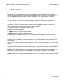
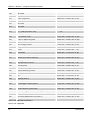
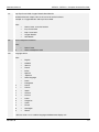
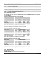
Ppeak (cmH2O)
23
13
5
Pmean
PEEP
RR (b/min)
20
41
O2 (%)
Ti/Ttot
40
30
5
45
35
0.48
MVe (l/min)
10.3
VTI
VTe
40.0
5.0
495
479
SERVO-i / SERVO-s, Computer Interface Emulator
1
INTRODUCTION ............................................................................................................4
1.1
1.2
1.3
2
3
4.4
4.5
4.6
4.7
4.8
4.9
General ............................................................................................................................................ 29
Empty command ............................................................................................................................ 29
Address Number AN ...................................................................................................................... 30
Alarm Output AO ............................................................................................................................ 30
Battery Check BC........................................................................................................................... 30
Change Time Out CT ..................................................................................................................... 30
Define Breath DB ........................................................................................................................... 30
Define Curve DC............................................................................................................................. 31
Firmware Version SV ..................................................................................................................... 31
Hello HO .......................................................................................................................................... 31
Read Breath RB.............................................................................................................................. 31
Read Curve RC ............................................................................................................................... 31
Read Sampling Time RS................................................................................................................ 32
Read Time RT ................................................................................................................................. 32
Read Version RV............................................................................................................................. 32
Change Sampling Time CS ........................................................................................................... 33
Set Time ST (not supported) ......................................................................................................... 33
Trend Output TO ............................................................................................................................ 33
Ultra Curve UC ............................................................................................................................... 34
Ultra Trend UT ................................................................................................................................ 36
Extended Commands..................................................................................................37
6.1
6.2
6.3
6.4
2
General .............................................................................................................................................. 9
Typographical conventions............................................................................................................. 9
Definitions and Acronyms ............................................................................................................... 9
4.3.1
Definitions ........................................................................................................................... 9
4.3.2
Date format....................................................................................................................... 10
4.3.3
Common acronyms .......................................................................................................... 10
The RS-232 communication settings........................................................................................... 11
Signal Handshake protocol........................................................................................................... 11
Error handling................................................................................................................................. 12
Performance ................................................................................................................................... 13
Support for different CIE Protocol versions................................................................................ 13
Channels ......................................................................................................................................... 14
4.9.1
Channel 00-99: ................................................................................................................. 14
4.9.2
Channel 100-199: ............................................................................................................. 16
4.9.3
Channel 200-299: ............................................................................................................. 17
4.9.4
Channel 300-399: ............................................................................................................. 19
4.9.5
Switch Parameters for Channels 300 to 399:................................................................... 22
4.9.6
Channel 400-499: ............................................................................................................. 26
4.9.7
Channel 500-999: ............................................................................................................. 28
Basic Commands ........................................................................................................29
5.1
5.2
5.3
5.4
5.5
5.6
5.7
5.8
5.9
5.10
5.11
5.12
5.13
5.14
5.15
5.16
5.17
5.18
5.19
5.20
6
References........................................................................................................................................ 8
Communication - General ............................................................................................9
4.1
4.2
4.3
5
General information ......................................................................................................................... 4
Operation .......................................................................................................................................... 5
Equipment combinations ................................................................................................................ 5
Functional Overview......................................................................................................6
Compatibility..................................................................................................................7
3.1
4
Reference Manual
General ............................................................................................................................................ 37
Empty command ............................................................................................................................ 38
Admit Patient ADMP ...................................................................................................................... 38
Discharge Patient DISP ................................................................................................................. 38
Revision 09
Reference Manual
6.5
6.6
6.7
6.8
6.9
6.10
6.11
6.12
6.13
6.14
6.15
6.16
6.17
6.18
6.19
6.20
6.21
6.22
6.23
6.24
6.25
6.26
6.27
6.28
7
Read Acquired Data RADA............................................................................................................ 38
6.5.1
Curve Data ........................................................................................................................ 38
6.5.2
Breath Data....................................................................................................................... 40
6.5.3
Settings Data .................................................................................................................... 40
6.5.4
Alarm Data ........................................................................................................................ 40
6.5.5
Alarm Data with extended output..................................................................................... 40
6.5.6
Trend Data ........................................................................................................................ 41
Read Acquired Data Continuously RADC.................................................................................... 43
Read Address Number RADN ....................................................................................................... 46
Read Alarm Output RALO ............................................................................................................. 46
Read Analog Input Code RAIC...................................................................................................... 46
Read Battery RBAT ........................................................................................................................ 46
Read Channel Configuration RCCO ............................................................................................. 47
Read CI Type RCTY ....................................................................................................................... 48
Read Data Acquisition Definition RDAD ...................................................................................... 48
Read Highest Protocol Version RHVE.......................................................................................... 49
Read Patient Info RPAI .................................................................................................................. 49
Read Protocol Version RPVE ........................................................................................................ 50
Read Serial Number RSEN ............................................................................................................ 50
Read Sampling Time RSTI............................................................................................................. 50
Read Software Version RSWV ...................................................................................................... 50
Read Text RETX ............................................................................................................................. 52
Read Time RTIM............................................................................................................................. 52
Read Time out RTOU ..................................................................................................................... 52
Set Data Acquisition Definition SDAD.......................................................................................... 53
Set Protocol Version SPVE............................................................................................................ 53
Set Sampling Time SSMP.............................................................................................................. 54
Set Time STIM (not supported)..................................................................................................... 54
Set Time Out STOU ........................................................................................................................ 54
Store Text STTX ............................................................................................................................. 54
Checksum Calculation ................................................................................................55
7.1
7.2
7.3
7.4
8
SERVO-i / SERVO-s, Computer Interface Emulator
General ............................................................................................................................................ 55
Formula ........................................................................................................................................... 55
Checksum transmission................................................................................................................ 55
Example........................................................................................................................................... 55
Revision History...........................................................................................................56
8.1
8.2
8.3
8.4
8.5
8.6
8.7
Revision 09
Reference Manual – Revision 03 .................................................................................................. 56
8.1.1
General changes – Revision 03 ........................................................................................ 56
8.1.2
History table – Revision 03 ............................................................................................... 56
Reference Manual – Revision 04 .................................................................................................. 57
8.2.1
History table – Revision 04 ............................................................................................... 57
Reference Manual – Revision 05 .................................................................................................. 58
8.3.1
History table – Revision 05 ............................................................................................... 58
Reference Manual – Revision 06 .................................................................................................. 59
8.4.1
History table – Revision 06 ............................................................................................... 59
Reference Manual – Revision 07 .................................................................................................. 60
8.5.1
History table – Revision 07 ............................................................................................... 60
Reference Manual – Revision 08 .................................................................................................. 62
8.6.1
History table – Revision 08 ............................................................................................... 62
Protocol version 003 – Reference Manual revision 09 ............................................................... 64
8.7.1
History table – Revision 09 ............................................................................................... 64
3
SERVO-i / SERVO-s, Computer Interface Emulator
1
Reference Manual
INTRODUCTION
1.1
General information
The purpose of this Reference Manual is to describe the design of the SERVO-i / SERVO-s Computer
Interface Emulator (CIE) Protocol version 0003, introduced with SERVO-i / SERVO-s System version 6.0.
The manual provides information about commands and responses in using the SERVO-i / SERVO-s
Computer Interface Emulator (CIE).
Updated revisions of the Reference Manual will be published when new CIE Protocol versions are released.
It is recommended to use the latest version of the Reference Manual, check on www.maquet.com for
updates.
The SERVO-i / SERVO-s Computer Interface Emulator (CIE) described herein interfaces an external
equipment via an RS-232C serial interface. This specification states the requirements for the
communication protocol between the CIE and an external equipment.
This Reference Manual is intended for programmers only.
Throughout this Reference Manual;
SERVO-i represents SERVO-i Ventilator System.
SERVO-s represents SERVO-s Ventilator System.
The information in this Reference Manual is valid for both SERVO-i and SERVO-s Computer Interface
Emulator (CIE) unless stated otherwise.
The SERVO-i / SERVO-s Computer Interface Emulator is an integrated part of the SERVO-i / SERVO-s
Ventilator System. In addition to the information given here, always pay attention to the information in the
User’s Manual.
The SERVO-i / SERVO-s Computer Interface Emulator must not be used as a component in a remote alarm
system.
The SERVO-i / SERVO-s Computer Interface Emulator described herein emulates the Computer Interface
(CI) of the Servo Ventilator 300/300A (SV 300) protocol, ref. [1], and the Servo Computer Module 990 (SCM
990) protocol, ref. [2], and interfaces an external equipment via an RS-232C serial interface.
MAQUET has no responsibility for the safe operation of the equipment if service or repair is done by a nonprofessional or by persons who are not employed by or authorized by MAQUET. We recommend that
service be done as part of a service contract with MAQUET.
Caution: Federal law in the USA restricts this device to sale by, or on the order of a physician (or a properly
licensed practitioner).
4
Revision 09
Reference Manual
1.2
SERVO-i / SERVO-s, Computer Interface Emulator
Operation
Due to factors not controlled by MAQUET, the correctness of processed metering values obtained from the
SERVO-i / SERVO-s Computer Interface Emulator cannot be guaranteed in all situations. It is therefore
recommended that the data is verified against actual preset and measured values of SERVO-i / SERVO-s.
If there should be any deviation between information shown on SERVO-i / SERVO-s and that shown by
external equipments, the parameters shown on SERVO-i / SERVO-s shall be considered the primary source
for information.
In the case of external equipment not recommended by MAQUET, MAQUET disclaims all responsibility for
the correctness of signals processed by such external equipment.
Data obtained from the SERVO-i / SERVO-s Computer Interface Emulator, which has been processed in
external equipments, must not be used as a substitute for therapeutic or diagnostic decisions. Such
decisions can be made only by staff with medical expertise, according to established and accepted
practice.
1.3
Equipment combinations
Only components, accessories, supplies and external equipment recommended by MAQUET should be
used with the system. The whole system must comply with the IEC 60601-series. Contact your local
MAQUET representative for further information regarding recommended equipment. Use of any other
components, accessories, supplies and external equipment may cause degraded system performance and
safety.
Revision 09
5
SERVO-i / SERVO-s, Computer Interface Emulator
2
Reference Manual
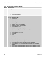
Functional Overview
Sampling time
1/minute
Real time
clock
Baud rate
Time out
Serial input
Input buffer
Curve buffer
Breath trend
parameters
buffer
Internal inputs
A/D converter,
generated
Internal
within the Servo… communication
Breath
parameters
buffer
Baud rate
Breath
completed
Serial output
Output buffer
Setting
parameters
buffer
Alarm
parameters
buffer
µ-Processor
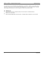
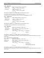
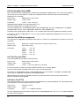
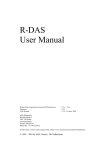
The information transfer between the CIE and the external equipment is performed via the serial
communication link. The external equipment acts as the master and transmits commands to the CIE in order to
retrieve information.
For Curve data, the desired channels, the sampling speed and the number of samples to be read by the
external equipment are defined by commands. Due to memory limitation, a maximum of 4 channels can be
sampled at the same time.
When a breath is completed, all applicable channels are read to the Breath parameters buffer. Once a minute a
number of channel data are stored into the Breath Trend parameters buffer, calculated as filtered values over
the last minute. The buffer stores trend values for the last 24 hours of operation. The channel numbers are
defined by the firmware of the CIE and cannot be changed.
Setting parameters buffer is updated at every change of settings, Alarm parameters buffer is updated every
500 ms.
On command from the external equipment , the parameter values are fed to the Output buffer and clocked out
via the serial port. In order to fulfill isolation requirements, the CIE uses opto couplers on the serial input and
output.
6
Revision 09
Reference Manual
3
SERVO-i / SERVO-s, Computer Interface Emulator
Compatibility
About SCM 990 compatibility
The SCM 990, Firmware version 2.1 protocol (see ref. [2]) is emulated - BASIC commands.
The following items are the major differences as compared with the SCM 990 – Reference Manual:
The minimum internal sampling period is 10 ms.
Aux. channels are emulated.
The SCM 990 internal battery. (Other voltage level emulated, corresponding to SV 300.)
The EXTENDED commands. (Not present in the SCM 990.)
More channels are trended, see further section 4.9.
The parameter Airway flow * 10, channel 13, only gives the Airway flow, channel 00, multiplied by 10.
The ‘Read Version’ command.
Communication settings.
About SV 300 compatibility
The SV 300 CI, Version 2.0 and above communication protocol (see ref. [1]) is emulated - EXTENDED
commands. The following items are the major differences as compared with the SV 300 – Reference Manual:
Aux. channels are emulated (channels: 32 - 39, 104 - 111, 214 - 221, 237).
Some channels are emulated and some are not supported, for further details see the section 4.9 and the
ref. [1] document.
Settings and alarm channels are not available as trends.
In SV 300, all basic channels 0-39 are available as both curve channels and breath channels. In SERVO-i /
SERVO-s, curve channels are available as breath channels but not vice versa.
In SV 300, it is possible to read all basic trend channels 0-33. In SERVO-i / SERVO-s, only the specified
trend channels are possible to read. For further details see section 4.9 and the ref. [1] document.
The minimum internal sampling period is 10 ms.
The commands ADMP, DISP, RADA, RADC, RADN, RAIC, RBAT, RCTY, RSWV, RV and STIM are modified
in SERVO-i / SERVO-s.
The commands RADAE, SDADE, RHVE, RPVE, SPVE and RSEN are added in SERVO-i / SERVO-s.
About SERVO-i / SERVO-s compatibility
The information in this Reference Manual is valid for both the SERVO-i and the SERVO-s Computer Interface
Emulator (CIE) unless stated otherwise.
To consider when writing a CIE driver
The CIE Protocol is designed to be backwards compatible. At startup, the functionality from CIE Protocol
version 001 (introduced with SERVO-i / SERVO-s System version V4.0) is available; refer to CIE Reference
Manual, Revision 07.
New or modified data channels are available after selecting higher CIE Protocol versions with the command
SPVE. The protocol version is selectable from CIE Protocol version 001 to highest for the current SERVO-i /
SERVO-s System version, read by the RHVE command. See chapter 4.8 Support for different CIE Protocol
versions.
Revision 09
7
SERVO-i / SERVO-s, Computer Interface Emulator
Reference Manual
The output from the command RSWV will be updated when a new SERVO-i / SERVO-s System SW version is
released. The output from the command RHVE will be updated when a new CIE Protocol version is released.
After sending a command to CIE, wait for the response or abort the command with ESC.
3.1
References
[1]
Servo Ventilator 300/300A, Computer Interface, Firmware version 2.X, Reference Manual,
Order No. 63 14 061 E380E.
[2]
Servo Computer Module 990, Firmware version 2.1, Reference Manual, Order No. 63 09 178 E357E.
8
Revision 09
Reference Manual
4
4.1
SERVO-i / SERVO-s, Computer Interface Emulator
Communication - General
General
The CIE emulates the SV 300 CI and the SCM 990 protocols and interfaces an external equipment via an RS232C serial interface.
The information transfer between the CIE and the external equipment is performed via a serial communication
line. The external equipment acts as the master and transmits commands to the CIE in order to retrieve
information.
Curve data, breath data, trend data, settings data, alarm data and technical information may be retrieved from
the ventilator through CIE.
4.2
Typographical conventions
When reading this manual, note that:
<>
Encloses abbreviations, numerical value, etc.
NN16
Means hexadecimal value.
[]
Encloses parameters that are not necessary to use.
{}
Encloses the set of valid data.
...
Indicates sequence.
4.3
Definitions and Acronyms
4.3.1 Definitions
Alarm
Alarm data is alarm information generated by the ventilator. Alarms are
not available as trends.
BASIC Mode
Only BASIC commands are valid, see further section 5.
Breath
Breath data changes at maximum once a breath.
Curve
Curve data changes very often and is typically used to draw real time
graphs. It is sampled periodically.
Edi
Electrical activity of the diaphragm
Extended Alarm data Alarm data that also contains information if the alarm is active, but
silenced on the ventilator.
EXTENDED Mode
Only EXTENDED commands are valid, see further section 6.
NAVA
Neurally Adjusted Ventilatory Assist
NIV
Non-invasive ventilation.
Parameter
CIE command parameter, i.e. extra information needed to define the
semantics of a given CIE command message. For instance, for a read
command the parameter designates the data to read.
Preset cycle time
The time equal to 1/CMV freq. (BPM).
Settings
Settings data represent panel settings. Settings are not available as
trends.
Technical
Technical information, e.g. module version, configuration, etc.
Trend
Trend data is calculated and stored as one value every minute.
Revision 09
9
SERVO-i / SERVO-s, Computer Interface Emulator
Reference Manual
4.3.2 Date format
Date format used by CIE:
Year 1990–1999 is encoded as 90–99, i.e. year 99 is interpreted as 1999.
Year 2000–2089 is encoded as 00–89, i.e. year 10 is interpreted as 2010.
The valid date range of SERVO-i / SERVO-s is 1970-01-01 – 2037-12-31.
4.3.3
AD
Common acronyms
Alarm data
BPM
Breaths per minute
BR
Breath data
BT
Breath data (as trend)
CI
Computer Interface
CIE
Computer Interface Emulator
CMV
Continuous Mandatory Ventilation
CPAP
Continuous Positive Airway Pressure
CU
Curve data
Exp time
Expiration time
Insp time
Inspiration time
N/A
Not applicable
PCB
Printed Circuit Board
PEEP
Positive End Expiratory Pressure
SCM 990
Servo Computer Module 990
SD
Settings data
SV 300
Servo Ventilator 300/300A
SV 900
Servo Ventilator 900C/D/E
10
Revision 09
Reference Manual
4.4
SERVO-i / SERVO-s, Computer Interface Emulator
The RS-232 communication settings
Baud rate:
9600
Data length:
7 or 8 bits
Stop bits:
1 or 2 bits
Parity:
Even
Data format:
ASCII or Binary (Binary format requires 8 data bits)
Handshake:
XON/XOFF
Both the Data length (7 or 8 bits) and Stop bits (1 or 2 bits) are auto-detected.
4.5
Signal Handshake protocol
The CIE enters BASIC mode at startup and when receiving the command ‘Hello’, HO. When CIE enters BASIC
mode, all activated channels are cleared.
In BASIC Mode the CIE only recognizes the BASIC commands and the ‘Read CI Type’, RCTY command,
which is an EXTENDED command.
In BASIC Mode when the CIE receives the command ‘Read CI Type’, RCTY, it will enter EXTENDED Mode.
When CIE enters EXTENDED Mode, all activated channels are cleared and the selected protocol version is set
to 001 (SERVO-i / SERVO-s V4.0).
In EXTENDED Mode the CIE only recognizes the EXTENDED commands and the ‘Hello’, HO command which
is a BASIC command.
Note that all requirements regarding channels and their output in EXTENDED Mode are only applicable for the
highest protocol version available.
The following control characters are used, in order to control the data flow from the CIE:
<CR> = 0D16
End of transmission. General character to be used to define the end of an instruction or end
of an ASCII response from the CIE.
Carriage Return character.
<LF> = 0A16
Line Feed character.
<EOT>= 0416
Issued by the external equipment to start the data flow from the CIE if the external
equipment has previously stopped the data flow. (Note 1)
Issued by the external equipment to stop the data flow from the CIE. Upon reception of
<XOFF>= 1316
XOFF, CIE stops transmission as soon as possible. (Note 1)
Issued by the external equipment to interrupt the data transfer from the CIE. Upon reception
<ESC> = 1B16
of ESC, CIE stops transmission and any running command, e.g. RADC, as soon as
possible. Transmission is restarted upon reception of the next valid command.
<CHK>
Calculated checksum (EXTENDED mode only). The checksum calculation is defined in
section 7.
Note 1: Some external equipment with automatic Xon/Xoff control may automatically remove the 1116 and
1316. To avoid this, it is recommended to implement Xon/Xoff control in the application
<XON>= 1116
Revision 09
11
SERVO-i / SERVO-s, Computer Interface Emulator
4.6
Reference Manual
Error handling
The CIE validates input data in order to detect errors. In case of error, the CIE replies with an error message
depending on the type of error and the command type, i.e. ASCII or binary.
The following error messages apply to commands with ASCII response:
Error
Error
code
BASIC commands
error message
EXTENDED commands
error message
Not a valid command
ER10
ER10<EOT>
ER10<CHK><EOT>
Syntax error, e.g. too many or too few
parameters
ER11
ER11<EOT>
ER11<CHK><EOT>
Parameter value out of range or parameter
not supported by the ventilator
ER12
ER12<EOT>
ER12<CHK><EOT>
No trend values, i.e. requested start time not ER13
within trend buffer, no trend values within the
time period requested, or requested trend
length less than one minute
ER13<EOT> (Note 1)
ER13<CHK><EOT> (Note 1)
Trend length error, i.e. requested trend
length exceeds available trend buffer
ER14
ER14<EOT> (Note 1)
ER14<CHK><EOT> (Note 1)
Trend channel not defined
ER15
ER15<EOT>
ER15<CHK><EOT>
CIE not configured
ER16
N/A
ER16<CHK><EOT>
Ventilator is in Standby mode
ER17
N/A
ER17<CHK><EOT>
Checksum error
ER18
N/A
ER18<CHK><EOT>
Buffer full
ER19
ER19<EOT>
ER19<CHK><EOT>
Note 1: Not applicable for SERVO-s of System version 1.0. No trend data is available in SERVO-s V1.0.
12
Revision 09
Reference Manual
SERVO-i / SERVO-s, Computer Interface Emulator
The following error messages apply to commands with Binary response:
Error
Error
BASIC commands
code
error message
Not a valid command
N/A
N/A
Syntax error, e.g. too many or too few
E00B7F
0B16
parameters
Parameter value out of range or parameter not 0C16
E00C7F
supported by the ventilator
No trend values, i.e. requested start time not
E00D7F (Note 1)
0D16
within trend buffer, no trend values within the
time period requested or requested trend
length less than one minute
Trend length error, i.e. requested trend length 0E16
E00E7F (Note 1)
exceeds available trend buffer
Trend channel not defined
E00F7F
0F16
EXTENDED commands
error message
N/A
E00B7F<CHK>
E00C7F<CHK>
E00D7F<CHK> (Note 1)
E00E7F<CHK> (Note 1)
E00F7F<CHK>
CIE not configured
1016
N/A
E0107F<CHK>
Ventilator is in Standby mode
1116
N/A
E0117F<CHK>
Checksum error
N/A
N/A
N/A
Buffer full
E0137F
E0137F<CHK>
1316
Note 1: Not applicable for SERVO-s of System version 1.0. No trend data is available in SERVO-s V1.0.
Note that since all CIE command messages are ASCII messages, the error ‘Not a valid command’ is always
returned as an ASCII response message. This is the reason why the error ‘Not a valid command’ is not
applicable as a binary response message.
Note that ‘Checksum error’ is always returned as an ASCII response message since it is not possible to
determine what command generated the error.
If it is not possible to calculate or retrieve data designated by a command parameter within the CIE, a ‘Missing
value’ is transferred, which is 9999 for ASCII and 7EFF16 for Binary.
4.7
Performance
The CIE needs to receive any character within set time-out; otherwise the previous characters are ignored.
See command CT, chapter 5.6, command RTOU, chapter 6.22 and command STOU, chapter 6.27 for more
information.
The CIE sends the first character of the response to all commands within 500 ms, unless otherwise stated in
the description of each specific command.
4.8
Support for different CIE Protocol versions
The CIE provides a mechanism for selecting between different protocol versions in EXTENDED Mode.
The following commands are used:
Read Highest Protocol Version, RHVE: Requests information about the highest available CIE Protocol
version for the current SERVO-i / SERVO-s System version.
Read Protocol Version, RPVE: Requests information about the CIE Protocol version currently in use.
Set Protocol Version, SPVE: Configures CIE to use a specific Protocol version.
The lowest selectable CIE Protocol version shall be 001. This protocol version will be selected when changing
from BASIC Mode to EXTENDED Mode.
The difference between protocol versions are that:
Existing channels can be deleted.
New channels can be added.
Configuration, or switch parameters, for existing channels can be changed.
New commands can be added.
Revision 09
13
SERVO-i / SERVO-s, Computer Interface Emulator
4.9
Reference Manual
Channels
Each parameter corresponds to a channel number. The following tables define channels and corresponding
parameter:
Channels 00 - 99 are reserved for the BASIC protocol.
Channels 100 - 999 are reserved for the EXTENDED protocol. The trend channel numbers are in this area
equivalent to channel No.
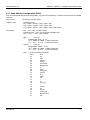
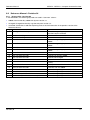
4.9.1 Channel 00-99:
Basic SCM 990 protocol channels according to ref. doc. [2].
CIE returns the raw value of a basic channel, which is graded in the unit [4.883mV]. The raw value 2048
corresponds to 0V. Thus, the value graded in engineering unit is calculated according to the following formula:
<value> = ((<raw_value> – 2048) * 4.883) / <scale_factor>
Note that the engineering unit is given by the scale factor of each channel, e.g. the channel airway flow has the
scale factor 5000mV/l/s, which gives the engineering unit [l/s].
All curve channels are available as breath channels as well, but not vice versa.
All curve data are based on internal transducer data (even with the SERVO-i option Y-piece measurement
active) unless stated as Y-piece curves. Most breath data are based on Y-piece data when Y-piece
measurement active.
CIE supports basic channels according to the following table:
Ch No
Trend No
0
1
20
2
Parameter Name
Scale Factor
Airway Flow (curve)
5000mV/l/s
Insp. Tidal vol. (breath)
5000mV/l
Airway Pressure Insp (curve)
50mV/cm H2O
3
21
Exp. Tidal vol. (breath)
5000mV/l
4
0
O2-concentration (breath)
50mV/%
5
22
Baro. Pressure (breath) (Note 3)
4883mV/Bar
6
33
Aux_Code (breath) (emulated = 2303)
4.883 mV/bit
7
1
Pause Pressure (breath)
50mV/cm H2O
8
2
Resp. rate calc (breath)
50mV/breaths/min
9
3
Peak pressure (breath)
50mV/cm H2O
10
4
Exp. minute vol. (breath)
200mV/l/min
11
23
Mean airway pressure (breath)
50mV/cm H2O
12
Airway Pressure Exp (curve)
50mV/cm H2O
13
Airway flow *10 (curve) (Note 4)
50000mV/l/s
14
Not Used (breath) (emulated = 2048)
15
CI Battery Voltage (curve) (emulated = 2826) (Note 2)
16
Not Used (breath) (emulated = 2048)
17
CO2 concentration (curve) (Note 1)
18
7
Ineff tidal volume (breath) (emulated = 2048)
19
8
Eff tidal volume (breath) (emulated = 2048)
20
9
CO2 tidal prod. (breath) (Note 1)
14
1000mV/V
1000mV/%CO2
100mV/ml CO2
Revision 09
Reference Manual
SERVO-i / SERVO-s, Computer Interface Emulator
21
10
End tidal CO2 conc. (breath) (Note 1)
1000mV/%CO2
22
11
CO2 minute prod. (breath) (Note 1)
10mV/ml CO2/min
23
12
Eff. Ventilation (breath) (emulated = 2048)
24
13
Tidal volume (breath) (emulated = 2048)
25
Airway pressure (breath) (emulated = 2048)
26
15
Exp. Resistance (breath)
20 mV/cm H2O/l/s
27
16
Static Compliance (breath)
10 mV/ml/cm H2O
28
17
End exp. Flow (breath)
1000 mV/l/s
29
18
End exp. pressure (breath)
100mV/cm H2O
30
19
End exp. lung pressure (breath) (emulated = 2048)
31
24
Insp. Resistance (breath)
32
25
AUX Channel 1 (curve) (emulated = 2048)
33
26
AUX Channel 2 (curve) (emulated = 2048)
34
27
AUX Channel 3 (curve) (emulated = 2048)
35
28
AUX Channel 4 (curve) (emulated = 2048)
36
29
AUX Channel 5 (curve) (emulated = 2048)
37
30
AUX Channel 6 (curve) (emulated = 2048)
38
31
AUX Channel 7 (curve) (emulated = 2048)
39
32
AUX Channel 8 (curve) (emulated = 2048)
40 - 99
20 mV/cm H2O/l/s
Not Used
Note 1: Not applicable for SERVO-s.
Note 2: The CI battery voltage is emulated since CIE has no battery of its own. CIE uses the Monitoring PCB
battery, which is managed and supervised by the Monitoring subsystem.
Note 3: Channel 5 is not used in the SCM 990.
Note 4: Min. value for CIE output is -0.2 l/s. Output for lower actual values will be set to -0.2 l/s.
Revision 09
15
SERVO-i / SERVO-s, Computer Interface Emulator
Reference Manual
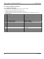
4.9.2 Channel 100-199:
Extended channels used for real-time curves. The configuration, i.e. actual scale factors and the voltage
ranges, is received via the command Read Channel Configuration (RCCO). For more information about the
configuration, see the description of the command RCCO.
All curve data are based on internal transducer data unless specified as Y-piece curves. When the SERVO-i
option Y-piece measurement is active, data from internal transducers may differ from those presented on the
User Interface. Also note that since this protocol uses one phase-flag for all curves, and Y-piece curve data are
delayed 50 ms compared to internal transducer curve data, the phase-information for Y-piece curve data will
be off by 50 ms.
CIE supports extended curve channels according to the following table:
Ch No
Parameter Name
Configuration (gain, offset, unit, type)
100
Airway Flow
+2713E-004, +3333E+000, 02, CU
101
Airway pressure (I)
+6510E-005, +1333E-001, 04, CU
102
Airway pressure (E)
+6510E-005, +1333E-001, 04, CU
103
CO2 concentration (%) (Note 1)
+1000E-004, +0000E+000, 07, CU
104
AUX Channel 1 (emulated = 2048)
+4883E-003, +1000E+001, 13, CU
105
AUX Channel 2 (emulated = 2048)
+4883E-003, +1000E+001, 13, CU
106
AUX Channel 3 (emulated = 2048)
+4883E-003, +1000E+001, 13, CU
107
AUX Channel 4 (emulated = 2048)
+4883E-003, +1000E+001, 13, CU
108
AUX Channel 5 (emulated = 2048)
+4883E-003, +1000E+001, 13, CU
109
AUX Channel 6 (emulated = 2048)
+4883E-003, +1000E+001, 13, CU
110
AUX Channel 7 (emulated = 2048)
+4883E-003, +1000E+001, 13, CU
111
AUX Channel 8 (emulated = 2048)
+4883E-003, +1000E+001, 13, CU
112
CI Battery Voltage (emulated = 2826)
+4883E-003, +1000E+001, 13, CU
113
Airway pressure
+6510E-005, +1333E-001, 04, CU
114
Volume
+4000E-004, +0000E+000, 01, CU
115
Y-piece Pressure (Note 1)
+6510E-005, +1333E-001, 04, CU
116
Y-piece Flow (Note 1)
+2713E-004, +3333E+000, 02, CU
117
Y-piece Volume (Note 1)
+4000E-004, +0000E+000, 01, CU
118
Edi (Note 1)
+2000E-005, +0000E+000, 19, CU
119
CO2 concentration (mmHg) (Note 1)
+1000E-004, +0000E+000, 10, CU
120 - 199 Not Used
Note 1: Not applicable for SERVO-s.
16
Revision 09
Reference Manual
SERVO-i / SERVO-s, Computer Interface Emulator
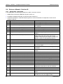
4.9.3 Channel 200-299:
Extended channels used for breath data. The configuration, i.e. actual scale factors and the voltage ranges, is
received via the command Read Channel Configuration (RCCO). For more information about the configuration
see the description of the command RCCO.
Most breath data will be based on Y-piece data when the SERVO-i option Y-piece measurement is active.
CIE supports extended breath channels according to the following table:
Ch No
Parameter Name
Configuration (gain, offset, unit, type)
200
Measured breath frequency
+1000E-004, +0000E+000, 06, BT
201
Exp. tidal volume
+1000E-003, +0000E+000, 01, BT
202
Insp. Tidal volume
+1000E-003, +0000E+000, 01, BT
203
Insp. Minute volume
+1000E-004, +0000E+000, 08, BT
204
Exp. minute volume
+1000E-004, +0000E+000, 08, BT
205
Peak pressure
+1000E-004, +0000E+000, 04, BT
206
Mean airway pressure
+1000E-004, +0000E+000, 04, BT
207
Pause pressure
+1000E-004, +0000E+000, 04, BT
208
End exp. pressure
+1000E-004, +0000E+000, 04, BT
209
O2 concentration
+1000E-004, +0000E+000, 07, BT
210
Barometric pressure
+1000E-003, +0000E+000, 12, BT
211
Gas supply pressure, Air
+1000E-001, +0000E+000, 12, BT
212
Gas supply pressure, O2
+1000E-001, +0000E+000, 12, BT
213
Gas supply pressure, Optional (emulated = 0)
+1000E-001, +0000E+000, 12, BT
214
AUX Channel 1 (emulated = 2048)
+4883E-003, +1000E+001, 13, BT
215
AUX Channel 2 (emulated = 2048)
+4883E-003, +1000E+001, 13, BT
216
AUX Channel 3 (emulated = 2048)
+4883E-003, +1000E+001, 13, BT
217
AUX Channel 4 (emulated = 2048)
+4883E-003, +1000E+001, 13, BT
218
AUX Channel 5 (emulated = 2048)
+4883E-003, +1000E+001, 13, BT
219
AUX Channel 6 (emulated = 2048)
+4883E-003, +1000E+001, 13, BT
220
AUX Channel 7 (emulated = 2048)
+4883E-003, +1000E+001, 13, BT
221
AUX Channel 8 (emulated = 2048)
+4883E-003, +1000E+001, 13, BT
222
Ineff. tidal volume (Note 2)
223
Eff. tidal volume (Note 2)
224
CO2 tidal production (Note 1)
+1000E-004, +0000E+000, 01, BT
225
End tidal CO2 concentration (%) (Note 1)
+1000E-004, +0000E+000, 07, BT
226
CO2 minute production (Note 1)
+1000E-003, +0000E+000, 03, BT
227
Eff. ventilation (Note 2)
228
Barometric Pressure 2nd (emulated = invalid = 7EFF16)
229
Not Used
Revision 09
+1000E-003, +0000E+000, 12, BT
17
SERVO-i / SERVO-s, Computer Interface Emulator
Reference Manual
230
Not Used
231
Exp. resistance
+1588E-004, +1000E-001, 09, BT
232
Static Compliance
+4976E-004, +2000E+000, 05, BT
233
End exp. Flow
+7100E-006, +3500E-002, 15, BT
234
Not Used
235
Not Used
236
Insp. Resistance
+4000E-004, +0000E+000, 09, BT
237
Aux_Code (emulated = 255)
-, -, -, BT
238
I:E Ratio (Note 3)
+1000E-005, +0000E+000, --, BT
239
Ti (Insufflation time)
+3300E-006, +0000E+000, 14, BR
240
C dyn i in Open Lung Tool
+5000E-004, +0000E+000, 05, BR
241
Dynamic Characteristics
+4976E-004, +2000E-001, 05, BT
242
NIV, Leakage fraction
+1310E-005, +0000E+000, 07, BT
243
Elastance
+1000E-004, +0000E+000, 16, BT
244
Ti/Ttot
+1100E-007, +0000E+000, --, BT
245
Total PEEP
+6510E-005, +1333E-001, 04, BT
246
Shallow Breathing Index (SBI) (Note 4)
+1000E-004, +0000E+000, --, BT
247
Spontaneous Breath frequency
+1000E-004, +0000E+000, 06, BT
248
Mve spont
+1000E-004, +0000E+000, 08, BT
249
MVespont/Mve in Bivent
+1100E-007, +0000E+000, --, BR
250
Time constant
+3300E-006, +0000E+000,14, BT
251
Work of Breathing, Ventilator
+1000E-005, +0000E+000, 18, BT
252
Work of Breathing, Patient
+1000E-005, +0000E+000, 18, BT
253
CPAP (Note 1)
+1000E-004, +0000E+000, 04, BT
254
P0.1
+6510E-005, +1333E-001, 04, BT
255
Edi peak (Note 1)
+2000E-005, +0000E+000, 19, BT
256
Edi min (Note 1)
+2000E-005, +0000E+000, 19, BT
257
% Edi trigger in NAVA (Note 1)
+1310E-005, +0000E+000, 07, BR
258
% Edi cycle off in NAVA (Note 1)
+1310E-005, +0000E+000, 07, BR
259
Shallow Breathing Index (SBI)
+1000E-003, +0000E+000, 22, BT
260
End tidal CO2 concentration (mmHg) (Note 1)
+1000E-004, +0000E+000, 10, BT
261
Stress Index (Note 1)
+1000E-006, +0000E+000, --, BT
262
Remaining Nebulization time (Note 1)
+1000E-004, +0000E+000, 23, BR
263 –299 Not Used
Note 1: Not applicable for SERVO-s.
Note 2: Not supported.
18
Revision 09
Reference Manual
SERVO-i / SERVO-s, Computer Interface Emulator
Note 3: CIE sends I:E Ratio in the format “value:1”. This format is also used by the SERVO-i / SERVO-s User
Interface as long as “value” >= 1. Example, CIE value 2.0 is displayed as 2.0:1. With a “value” < 1 the I:E Ratio
is displayed in the format “1:1/value”. Example, CIE value 0.5 is displayed as 1:2.0.
Note 4: Obsolete but supported for backward compatibility. Use channel 259 instead.
4.9.4 Channel 300-399:
Extended channels used for settings. The configuration, i.e. actual scale factors and the voltage ranges, are
received via the command Read Channel Configuration (RCCO). For more information about the configuration
see the description of the command RCCO.
CIE supports extended settings channels according to the following table:
Ch No
Parameter Name
Configuration (gain, offset, unit, type)
300
CMV Frequency, Set
+1000E-004, +0000E+000, 06, SD
301
Insp. Time %, Set
+1000E-004, +0000E+000, 07, SD
302
Pause time %, Set
+1000E-004, +0000E+000, 07, SD
303
SIMV Frequency, Set
+1000E-004, +0000E+000, 06, SD
304
Insp. Rise time %, Set
+1000E-004, +0000E+000, 07, SD
305
Minute Volume, Set
+1000E-005, +0000E+000, 08, SD
306
Pressure Control Level above PEEP, Set
+1000E-004, +0000E+000, 04, SD
307
Pressure Support Level above PEEP, Set
+1000E-004, +0000E+000, 04, SD
308
PEEP, Set
+1000E-004, +0000E+000, 04, SD
309
Patient range selection, Set
-, -, -, SD (Note 3)
310
Ventilation Mode, Set
-, -, -, SD (Note 3)
311
Insp./Exp. Pause Hold, Oxygen Breaths/Start Breaths -, -, -, SD (Note 3)
312
CPAP, Set (Note 1)
+1000E-004, +0000E+000, 04, SD
313
Exp. minute vol. Upper alarm limit, Set (Note 4)
+1000E-004, +0000E+000, 08, SD
314
Exp. minute vol. Lower alarm limit , Set (Note 4)
+1000E-004, +0000E+000, 08, SD
315
Upper pressure limit, Set
+1000E-003, +0000E+000, 04, SD
316
EtCO2 concentration Upper alarm limit, Set (%)
(Note 1)
+1000E-005, +0000E+000, 07, SD
317
EtCO2 concentration Lower alarm limit, Set (%)
(Note 1)
+1000E-005, +0000E+000, 07, SD
318
O2 concentration Upper alarm limit
+1000E-004, +0000E+000, 07, SD
319
O2 concentration Lower alarm limit
+1000E-004, +0000E+000, 07, SD
320
Not Used
321
Not Used
322
Alarm mute/pre-mute Status
-, -, -, SD (Note 3)
323
O2 concentration, Set
+1000E-004, +0000E+000, 07, SD
324
Valve slot 1, binary code (emulated = 1)
-, -, -, SD
325
Valve slot 2, binary code (emulated = 2)
-, -, -, SD
Revision 09
19
SERVO-i / SERVO-s, Computer Interface Emulator
Reference Manual
326
Valve slot 3, binary code (emulated = 63)
-, -, -, SD
327
Trigger sensitivity level below PEEP, Set
-1000E-004, +0000E+000, 04, SD
328
Trigger sensitivity level above PEEP, Set
+1000E-004, +0000E+000, --, SD
329
Language switch
-, -, -, SD (Note 3)
330
Displayed CO2 Unit (Note 1)
-, -, -, SD (Note 3)
331
CO2 Mode (Note 2)
332
CO2 Execution Mode (Note 2)
333
I:E Ratio, Set (Note 5)
+1000E-005, +0000E+000, --, SD
334
Tidal volume, Set
+1000E-003, +0000E+000, 01, SD
335
Backup RR, Set
+1000E-004, +0000E+000, 06, SD
336
Backup Ti in Seconds, Set
+1000E-005, +0000E+000, 14, SD
337
NIV Program Status
-, -, -, SD (Note 3)
338
High-pressure level in BIVENT, Set
+1000E-004, +0000E+000, 04, SD
339
High pressure level time in BIVENT, Set
+1000E-005, +0000E+000, 14, SD
340
Low pressure level, PEEP, time in BIVENT, Set
+1000E-005, +0000E+000, 14, SD
341
Pressure Support level above Phigh in BIVENT, Set
+1000E-004, +0000E+000, 04, SD
342
Pressure Support level above PEEP in BIVENT, Set
+1000E-004, +0000E+000, 04, SD
343
Insp. Time in Seconds, Set
+1000E-005, +0000E+000, 14, SD
344
Pause Time in Seconds, Set
+1000E-005, +0000E+000, 14, SD
345
Insp. Rise time, in Seconds, Set
+1000E-005, +0000E+000, 14, SD
346
SIMV Breath duration, Set
+1000E-005, +0000E+000, 14, SD
347
Back-up Pressure Level Above PEEP, Set
+1000E-004, +0000E+000, 04, SD
348
Insp. flow, Set
+1000E-006, +0000E+000, 15, SD
349
Suction support Status
-, -, -, SD (Note 3)
350
Cycle off Fraction Level, Set
+1000E-005, +0000E+000, 07, SD
351
Circuit compliance compensation Status
-, -, -, SD (Note 3)
352
Trigger timeout in Automode
+1000E-005, +0000E+000, 14, SD
353
Breath frequency Upper alarm limit, Set
+1000E-004, +0000E+000, 06, SD
354
Breath frequency Lower alarm limit, Set
+1000E-004, +0000E+000, 06, SD
355
Apnea alarm time limit, Set (Note 6)
+1000E-004, +0000E+000, 14, SD
356
PEEP Lower alarm limit, Set
+1000E-004, +0000E+000, 04, SD
357
PEEP Upper alarm limit, Set
+1000E-004, +0000E+000, 04, SD
358
CPAP Upper alarm limit, Set (Note 1)
+1000E-004, +0000E+000, 04, SD
359
CPAP Lower alarm limit, Set (Note 1)
+1000E-004, +0000E+000, 04, SD
360
Y-piece measurement status (Note 1)
-, -, -, SD (Note 3)
361
Edi trigger (Note 1)
+2000E-006, +0000E+000, 19, SD
20
Revision 09
Reference Manual
SERVO-i / SERVO-s, Computer Interface Emulator
362
NAVA level (Note 1)
+3000E-006, +0000E+000, 21, SD
363
Gas Type Setting (Note 1)
-, -, -, SD (Note 3)
364
Exp. minute vol. Upper alarm limit, Set
+1000E-005, +0000E+000, 08, SD
365
Exp. minute vol. Lower alarm limit, Set
+1000E-005, +0000E+000, 08, SD
366
EtCO2 concentration Upper alarm limit, Set (mmHg)
(Note 1)
+1000E-004, +0000E+000, 10, SD
367
EtCO2 concentration Lower alarm limit, Set (mmHg)
(Note 1)
+1000E-004, +0000E+000, 10, SD
368
Backup Tidal Volume, Set
+1000E-003, +0000E+000, 01, SD
369
Backup I:E Ratio, Set (Note 5)
+1000E-005, +0000E+000, --, SD
370
Apnea audio delay, Set
+1000E-004, +0000E+000, 14, SD
371
Leakage fraction too high alarm, Set (Note 1)
-, -, -, SD (Note 3)
372
Nebulization mode, Set (Note 1)
-,-,-, SD
373
Nebulization time, Set (Note 1)
+1000E-004, +0000E+000, 23, SD
374–399
Not Used
Note 1: Not applicable for SERVO-s.
Note 2: Not supported.
Note 3: See 4.9.5 Switch Parameters for channels No. 300 to 399.
Note 4: Obsolete but supported for backward compatibility. Use channels 364/365 instead.
Note 5: CIE sends I:E Ratio in the format “value:1”. This format is also used by the SERVO-i / SERVO-s User
Interface as long as “value” >= 1. Example, CIE value 2.0 is displayed as 2.0:1. With a “value” < 1 the
I:E Ratio is displayed in the format “1:1/value”. Example, CIE value 0.5 is displayed as 1:2.0.
Note 6: Apnea alarm time limit value = 46 Apnea alarm (part of Ch 412, Apnea alarm/Backup ventilation)
disabled.
Revision 09
21
SERVO-i / SERVO-s, Computer Interface Emulator
Reference Manual
4.9.5 Switch Parameters for Channels 300 to 399:
Ch No Switch Parameters
309
Patient range selection, Set
Value:
310
1
=
Neonate
2
=
Adult
3
=
Pediatric (Not supported)
Ventilation Mode, Set
Value when ”automode” is OFF:
1
=
Value not used
2
=
Pressure Control
3
=
Volume Control
4
=
Pressure Reg. Volume Control
5
=
Volume Support
6
=
SIMV (Vol. Contr.) + Pressure Support
7
=
SIMV (Press. Contr.) + Pressure Support
8
=
Pressure Support / CPAP
9
=
Ventilation mode not supported by CIE
10
=
SIMV (Pressure Reg. Volume Control) + Pressure Support
11
=
Bivent
12
=
Pressure Control in NIV
13
=
Pressure Support / CPAP in NIV
14
=
Nasal CPAP
15
=
NAVA
16
=
Value not used
17
=
NIV NAVA
Value when ”automode” is ON:
22
18
=
Pressure Control, patient does not trigger the ventilator
19
=
Volume Control, patient does not trigger the ventilator
20
=
Pressure Reg. Volume Control, patient does not trigger the ventilator
21
=
Pressure Support / CPAP (switches to mode 18 if the patient does not trigger the
ventilator)
22
=
Volume Support (switches to mode 19 if the patient does not trigger the ventilator)
23
=
Volume Support (switches to mode 20 if the patient does not trigger the ventilator)
Revision 09
Reference Manual
311
SERVO-i / SERVO-s, Computer Interface Emulator
Insp./Exp Pause Hold, Oxygen Breaths/Start Breaths
Combined channel. Output value is the sum of all active functions.
Example: 5 = Oxygen breaths and Insp. Pause hold.
Value:
322
0
=
Normal state, no active function
1
=
Insp. Pause hold
2
=
Exp. Pause hold
4
=
Oxygen breaths
8
=
Start breath
Alarm mute/pre-mute Status
Value:
329
8
=
Normal state
10
=
Alarm muted/pre-muted
Language Switch
Value:
0
=
English
1
=
Swedish
2
=
German
3
=
French
4
=
Italian
5
=
Spanish
6
=
Japanese
7
=
Other language
8
=
Dutch
9
=
Portuguese
10
=
Danish
11
=
Turkish
12
=
Greek
13
=
Chinese
14
=
Russian
15
=
Polish
16
=
Hungarian
17
=
Czech
18
=
Finnish
19
=
Norwegian
20
=
Slovak
In SV 300, value 0-15 is used for language and barometer display unit.
Revision 09
23
SERVO-i / SERVO-s, Computer Interface Emulator
330
Reference Manual
Displayed CO2 Unit
Value:
337
1
=
%
2
=
kPa (Note 1)
4
=
mmHg (Note 2)
NIV Program Status
Value:
349
0
=
Undefined Status
1
=
Waiting position
2
=
Ventilation
3
=
Disconnected
Suction Support Status
Value:
351
0
=
Undefined Status
1
=
Normal ventilation
2
=
Waiting for disconnect
3
=
Disconnected
4
=
Post oxygenation
Circuit compliance compensation Status
Value:
360
1
=
OFF
2
=
ON
Y-piece Measurement Status
Value:
363
1
=
Inactive
2
=
Active
Gas Type Setting
Value:
24
0
=
Undefined Gas Type
1
=
Heliox
2
=
Air
Revision 09
Reference Manual
371
SERVO-i / SERVO-s, Computer Interface Emulator
Leakage fraction too high alarm, Set
Value:
372
1
=
Alarm OFF
2
=
Alarm ON
Nebulization mode, Set
Value:
1 = OFF
2 = Intermittent
3 = Continuous
Note 1: The following formula is used to convert from % to kPa:
Value [%]
x
Barometric Pressure [mbar]
1000
Barometric Pressure can be reached via channel 210.
Note 2: The following formula is used to convert from % to mmHg:
760 [mmHg]
1013 [mbar]
Revision 09
x
Barometric Pressure [mbar]
x
Value [%]
100
25
SERVO-i / SERVO-s, Computer Interface Emulator
Reference Manual
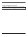
4.9.6 Channel 400-499:
Extended channels used for alarms. The configuration, i.e. actual scale factors and the voltage ranges, are
received via the command Read Channel Configuration (RCCO). For more information about the configuration,
see the description of the command RCCO.
CIE supports alarm channels according to the following table:
Ch No
Parameter Name
400
O2 conc. too high – alarm
401
O2 conc. too low – alarm
402
EtCO2 conc. too high – alarm (Note 1)
403
EtCO2 conc. too low – alarm (Note 1)
404
Breathing system µP Module error – alarm (emulated = 0)
405
Inspiratory control µP Module error – alarm (emulated = 0)
406
Panel Interface µP Module error – alarm (emulated = 0)
407
Exp. flow & CO2 linearization µP Module error – alarm (emulated = 0) (Note 1)
408
Monitoring System µP Module error – alarm (emulated = 0)
409
Computer Interface Emulator technical error – alarm (emulated = 0)
410
Airway pressure alarm Upper pressure limit exceeded – alarm
411
Exp. minute volume – alarm
One or more of following alarms:
Exp. minute volume too high
Exp. minute volume too low
412
Apnea alarm/Backup ventilation
One or more of following alarms:
Apnea
No Patient Effort
No Consistent Patient Effort
Check Catheter position – RR and HR coupling
Check Catheter position – Edi Invalid
413
Gas supply alarm
414
Battery alarm
One or more of following alarms:
Limited battery capacity
No battery capacity
415
Not Used
416
Power Failure – alarm
One or more of following alarms:
-12V too low/high
12V too low/high
24V too low/high
417
Mains Failure – alarm
418
O2 potentiometer error – alarm (emulated = 0)
419
CMV potentiometer error – alarm (emulated = 0)
26
Revision 09
Reference Manual
SERVO-i / SERVO-s, Computer Interface Emulator
420
Range Switch error – alarm (emulated = 0)
421
Mode Switch error – alarm (emulated = 0)
422
Barometer error – alarm
One or more of following alarms:
Baro. Press. too high
Baro. Press. too low
423
High continuous pressure – alarm
424
Overrange – alarm
One or more of following alarms:
Insp. Tidal volume overrange
Insp. Flow overrange
425
O2 cell disconnect – alarm
426
Computer Interface Emulator Internal communication failure – alarm
One or more of following alarms:
Panel/Breathing/ExpFlowMtr disconnect
Panel/Breathing/ExpFlowMtr connect timeout
427
Computer Interface Emulator hardware error – alarm (emulated = 0)
428
Alarm buff (emulated = 0)
429
CI Battery Voltage – alarm (emulated = 0)
430
Time in waiting position exceeds 2 min
431
No Patient Effort
432
Leakage out of range
433
Check tubing
434
Regulation pressure limited
435
Breath frequency High
436
Breath frequency Low
437
PEEP Low
438
PEEP High
439
CPAP High (Note 1)
440
CPAP Low (Note 1)
441
Pneumatic-Edi out of synch (Note 1)
442
Edi activity low (Note 1)
443
No Edi signal detected (Note 1)
444
Unsuccessful manual gas change alarm (Note 1)
445
Exp. Minute volume too high – alarm
446
Exp. Minute volume too low – alarm
447
Check Heliox adapter (Note 1)
448
Unreliable Edi signal (Note 1)
449
Check Catheter position – Edi Invalid (Note 1)
450
Check Catheter position – RR and HR coupling (Note 1)
Revision 09
27
SERVO-i / SERVO-s, Computer Interface Emulator
451
No Consistent Patient Effort
452
Leakage fraction too high (Note 1)
453–497
Not Used
498
High Priority Alarm
Reference Manual
499
Computer Interface Emulator Summary Alarm
Note 1: Not applicable for SERVO-s.
The data output of the alarm channels is configurable with the command SDADA, or SDADE (alarm channels
with extended output).
Alarm data output without any alarm channels configured:
Alarm status
Readout command
RALO
RADAA
RADAE
RADC
(Note 1)
(Note 1)
(Note 2)
No alarm
0
ER16
ER16
1016
Alarm active
1
ER16
ER16
1016
Alarm active but silenced
1
ER16
ER16
1016
Note 1: ASCII coded error message ER16, CIE not configured.
Note 2 Binary coded error message E0107F16, CIE not configured.
Alarm data output when configured with SDADA:
Alarm status
Readout command
RALO
RADAA
RADAE
RADC
Note 1
No alarm
0
0
ER16
0016
Alarm active
1
1
ER16
FF16
Alarm active but silenced
1
1
ER16
FF16
Note 1: ASCII coded error message ER16, CIE not configured.
Alarm data output when configured with SDADE:
Alarm status
Readout command
RALO
RADAA
RADAE
RADC
Note 1
No alarm
0
ER16
0
0016
Alarm active
1
ER16
1
0116
Alarm active but silenced
2
ER16
2
0216
Note 1: ASCII coded error message ER16, CIE not configured.
4.9.7 Channel 500-999:
Extended channels not used.
500-999
28
Not Used
Revision 09
Reference Manual
5
5.1
SERVO-i / SERVO-s, Computer Interface Emulator
Basic Commands
General
The BASIC commands below are according to the SCM 990, Firmware version 2.0 protocol,
see ref. [2].
Equipment administration commands:
Empty command
The empty command can be used for connection check.
Address Number, AN
Reads the address number of the ventilator (emulated).
Battery Check, BC
Reads the internal battery voltage (emulated).
Change Time Out, CT
Defines the command timeout.
Firmware Version, SV
Reads the firmware version.
Hello, HO
General call from the external equipment to the CIE to check
the connection.
Read Time, RT
Reads the Real Time Clock.
Read Version, RV
Reads the version of the ventilator.
Set Time, ST
Sets the Real Time Clock (not supported).
Data acquisition commands:
Define Breath, DB
Defines which channels to be read by the instruction Read
Breath.
Read Breath, RB
Reads the channels defined by the command Define Breath.
Change Sampling Time, CS
Sets the sampling time in milliseconds.
Read Sampling Time, RS
Reads the sampling time in milliseconds.
Define Curve, DC
Defines which channels to be read by the instruction Read
Curve or Ultra Curve.
Read Curve, RC
Reads the channels defined by the command Define Curve.
Ultra Curve, UC
Reads the values, in compressed binary format, of the
channels defined by the command Define Curve.
Alarm Output, AO
Requests alarm status.
Trend Output, TO
Reads one of the trend channels from the trend memory.
Ultra Trend, UT
Reads one of the trend channels from the trend memory
(compressed binary).
5.2
Empty command
CIE responds to the empty command in basic mode.
Input syntax:
<EOT>
Output syntax:
*<EOT>
Revision 09
29
SERVO-i / SERVO-s, Computer Interface Emulator
5.3
Reference Manual
Address Number AN
The CIE returns the address number of the SERVO-i / SERVO-s Ventilator unit (emulated).
Input syntax:
AN<EOT>
Output syntax:
<n><EOT>
Emulated Output:
00<EOT>
Parameters:
<n> = 00-99
5.4
Alarm Output AO
The CIE returns the summary alarm status.
Input syntax:
AO<EOT>
Output syntax:
<value><EOT>
Parameters:
<value> = {0 (no alarm),1 (alarm)}
When SERVO-i / SERVO-s is in standby mode this command returns ER10, i.e. it is not a valid
command in standby mode.
5.5
Battery Check BC
The CIE returns the internal battery voltage.
Input syntax:
BC<EOT>
Output syntax:
<value><EOT>
Emulated Output:
380<EOT>
Parameters:
<value> = 000-999 (steps of 10 mV)
Since CIE has no battery of its own within SERVO-i / SERVO-s, the emulated value 380 (3.8 V) is returned.
5.6
Change Time Out CT
This command defines the input character timeout.
Input syntax:
CT<value><EOT>
Output syntax:
*<EOT>
Parameters:
<value> = 001-250 (steps of 0.1 seconds)
If this command has not been received, the default timeout of 10 seconds applies.
The new timeout will be activated within 500 ms after command is received.
The timeout is shared between Basic and Extended mode, e.g. if the timeout is changed in basic mode,
the new value is applicable in both basic and extended mode.
When receiving a command, CIE needs to receive any character within the set time-out. Otherwise the
previous characters will be ignored.
5.7
Define Breath DB
This command defines which channels to be read by the instruction Read Breath. A minimum of 1 and a
maximum of 32 channels can be defined. It is possible to choose an arbitrary number of channels in arbitrary
row of order. The definition is valid until next time the command Define Breath is issued.
Input syntax:
DB<n1>[<n2>...<n32>]<EOT>
Output syntax:
*<EOT>
Parameters:
<n1>...<n32> = 00 – 39, channel number
The new channel table is activated within 500 ms after the response has been sent.
30
Revision 09
Reference Manual
5.8
SERVO-i / SERVO-s, Computer Interface Emulator
Define Curve DC
This command defines which channels to be read by the instruction Read Curve or Ultra Curve. A minimum of
1 and a maximum of 4 channels can be defined. It is possible to choose an arbitrary number of channels in
arbitrary row of order. The definition is valid until next time the command Define Curve is issued.
Input syntax:
DC<n1>[<n2>...<n4>]<EOT>
Output syntax:
*<EOT>
Parameters:
<n1>...<n4> = 00 – 39, channel number
The new channel is activated within 500 ms after the variable has been set.
5.9
Firmware Version SV
This command requests information about the firmware version. The reason for this command is only to keep
compatibility with the SCM 990, see ref. [2].
Input syntax:
SV<EOT>
Output syntax:
002200<EOT>
5.10 Hello HO
This command is a general call from the external equipment to the CIE to check the connection. The reason for
this command is only to keep compatibility with the SCM 990, see ref. [2].
Input syntax:
HO<EOT>
Output syntax:
900PCI<EOT>
Please see section 4.5 for further details about this command.
5.11 Read Breath RB
This command reads the channels defined by the command Define Breath. The read channel information
always comes from the last completed breath cycle.
Input syntax:
RB<EOT>
Output syntax:
<value(0)>...<value(n)><EOT>
Parameters:
<value(0)>...<value(n)> = 0000 – 9999
n = 0 – 31
When SERVO-i / SERVO-s is in standby mode, this command returns ER10, i.e. it is not a valid command in
standby mode.
5.12 Read Curve RC
This command reads the channels defined by the command Define Curve. When CIE receives this command,
it waits until the given trigger condition <trigger_point> is true, e.g. start of inspiration. Then CIE samples the
defined curve channels and returns the result periodically until the requested number of samples are returned.
The sampling period is defined by the command Change Sampling Time.
Input syntax:
RC<n>[<trigger_point>]<EOT>
Output syntax:
<time_phase>[<value(1,1)><value(2,1)><value(3,1)><value(4,1)>]...
<time_phase>[<value(1,n)><value(2,n)><value(3,n)><value(4,n)>]<EOT>
Revision 09
31
SERVO-i / SERVO-s, Computer Interface Emulator
Parameters:
Reference Manual
n = 0001 – 1500, number of samples
<trigger_point> = {
0 (free run),
1 (start insp), (default)
2 (end insp),
3 (start exp),
4 (end exp)}
<time_phase> =
{
I (insp time),
P (pause time),
E (exp time)}
<value(1,1)>...<value(4,n)> = 0000 – 9999
During Nasal CPAP:
<trigger_point> ignored and treated as 0 (free run)
<time_phase> will always be E (exp time)
The maximum time difference between transmitted value and sampled value is less than 500 ms.
When SERVO-i / SERVO-s is in standby mode, this command returns ER10, i.e. it is not a valid command in
standby mode.
If SERVO-i / SERVO-s is set in standby mode before the <trigger_point> is reached, this command returns
ER10.
5.13 Read Sampling Time RS
This command reads the set sampling time (in milliseconds). See further the command Change Sampling
Time.
Input syntax:
RS<EOT>
Output syntax:
<value><EOT>
Parameters:
<value> = 010 – 224 (ms)
5.14 Read Time RT
This command reads the Real Time Clock.
Input syntax:
RT<EOT>
Output syntax:
<year><month><day><hour><minute><sec><EOT>
Parameters:
<year>
<month>
<day>
<hour>
<minute>
<sec>
= 00 – 99
= 01 – 12
= 01 – 31
= 00 – 23
= 00 – 59
= 00 – 59
5.15 Read Version RV
This command reads the ventilator product name.
Input syntax:
RV<EOT>
Output syntax:
SERVO-i
Servo-i<EOT>
SERVO-s
Servo-s<EOT>
32
Revision 09
Reference Manual
SERVO-i / SERVO-s, Computer Interface Emulator
5.16 Change Sampling Time CS
This command sets the sampling time (in milliseconds). The default sampling time is 20 ms. Only one sampling
time can be set at a time to be valid for all sampled channels until next time the command Change Sampling
Time is received.
Input syntax:
CS<value><EOT>
Output syntax:
*<EOT>
Parameters:
<value> = 004 – 224 (ms)
Odd requested sampling time is decremented by 1 ms.
The new sampling time is activated within 500 ms.
The new sampling time is shared between Basic and Extended mode, e.g. if the sampling time is changed in
extended mode, the new value is applicable in both basic and extended mode.
Furthermore the sampling time is persistent, i.e. it is stored in persistent memory between ventilator sessions.
The minimum internal sampling time is 10 ms. In cases where the requested sampling time is less than 10 ms,
it is set to 10 ms.
5.17 Set Time ST (not supported)
This command is supposed to set the Real Time Clock. It is not supported anymore since it affects the existing
trend data.
Input syntax:
ST<year><month><day><hour><minute><EOT>
Output syntax:
ER10<EOT>
Parameters:
<year>
<month>
<day>
<hour>
<minute>
= 00 – 99
= 01 – 12
= 01 – 31
= 00 – 23
= 00 – 59
5.18 Trend Output TO
This command reads one of the trend channels from the trend memory, the last value is presented first.
Input syntax:
TO<k>[<start_time>]<length><EOT>
Output syntax:
SERVO-i / SERVO-s
<t0>,<value(0)>,<value(-1)>...
[;<t1>,<value(-x)>,...,<value(-n+1) >]<EOT>
SERVO-s of
System version 1.0
Revision 09
ER15<EOT>
No trend data is available in SERVO-s v1.0
33
SERVO-i / SERVO-s, Computer Interface Emulator
Parameters:
<k>
= 00 – 33, trend channel number
<year>
<month>
<day>
<hour>
<minute>
<sec>
= 00 – 99
= 01 – 12
= 01 – 31
= 00 – 23
= 00 – 59
= 00 – 59
<start_time>
= <year><month><day><hour><min><sec>
<length>
= <hour><min><sec>
<t0>,<t1>
= <year><month><day><hour><min><sec>
Reference Manual
<value(0)>...<value(-n + 1)> = 0000 – 9999
If no <start_time> is selected, the default <start_time> will be the time of the last trend value.
The first time stamp <t0> of the response is mandatory, in case there are any trend values to return.
Subsequent time stamps <t1> are given in case of discontinuities in the trend, e.g. if the SERVO-i has been
turned off for a while.
5.19 Ultra Curve UC
This command reads the values, in compressed binary format, of the channels defined by the command Define
Curve. When CIE receives this command, it waits until the given trigger condition <trigger_point> is true, e.g.
start of inspiration. Then CIE samples the defined curve channels and returns the result periodically until the
requested number of samples are returned. The sampling period is defined by the command Change Sampling
Time.
Input syntax:
UC<n>[<trigger_point>]<EOT>
Normal Output syntax: <phase_flag><phase>[<value_flag><value(1,1)>
<value_flag><value(2,1)><value_flag><value(3,1)>
<value_flag><value(4,1)>][<diff_value(1,2)>
<diff_value(2,2)><diff_value(3,2)><diff_value(4,2)>]...
<phase_flag><phase>[<diff_value(1,X)><diff_value(2,X)>
<diff_value(3,X)><diff_value(4,X)>]...
[<value_flag><value(1,Y)>< diff_value(2,Y)>< diff_value(3,Y)>
< diff_value(4,Y)>]...
[<diff_value(1,n)><diff_value(2,n)><diff_value(3,n)>
<diff_value(4,n)>]
<end_flag>
Output syntax in case
of error:
34
<error_flag><error><end_flag>
Revision 09
Reference Manual
Parameters:
SERVO-i / SERVO-s, Computer Interface Emulator
n = 0001 – 1500 (number of samples, ASCII)
<trigger_point> = {
0 (free run, ASCII),
1 (start insp, ASCII) – default
2 (end insp, ASCII),
3 (start exp, ASCII),
4 (end exp, ASCII)}
<phase_flag> = 8116
<phase> = {
1016 (insp time),
2016 (pause time),
3016 (exp time)}
<error_flag> = E016
<error> = XX16 (binary error code)
<value_flag> = 8016
<value(1,1)>...<value(4,n)> = 000016 – 7EFF16 (MSB first)
<diff_value(1,2)>...<diff_value(4,n)> = 8216 – 7E16
(8216 = -12610 ; 7E16 = 12610)
<end_flag> =
7F16
During Nasal CPAP:
<trigger_point> ignored and treated as 0 (free run)
<phase> will always be 3016 (exp time)
The CIE transmits the channel values according to the channel table set up by the command Define Curve.
The CIE responds to the command within 500 ms after the <trigger_point>. The maximum time difference
between transmitted value and sampled value is less than 500 ms.
Values are sent as differences <diff_value> when possible in order to save bandwidth, where <diff_value> is
the difference between the current and the preceding value, i.e. <diff_value> = <value(t)> - <value(t-1)>.
Absolute values <value> are sent the first time and when the difference is to large. An absolute value will be
preceded by a value flag <value_flag>.The most significant byte (MSB) of an absolute value is sent first.
The breath phase <phase> is sent the first time and then only upon breath phase changes. It is preceded by a
phase flag <phase_flag>.
When SERVO-i / SERVO-s is in standby mode this command returns ER10, i.e. it is not a valid command in
standby mode.
If SERVO-i / SERVO-s is set in standby mode before the <trigger_point> is reached, this command returns
ER10.
Revision 09
35
SERVO-i / SERVO-s, Computer Interface Emulator
Reference Manual
5.20 Ultra Trend UT
This command reads one of the trend channels from the trend memory, the last value is presented first.
Compressed binary coded format is used (8 data bits).
Input syntax:
UT<k>[<start_time>]<length><EOT>
SERVO-i / SERVO-s
<time_flag><t0><value_flag><value(0)><diff_value(-1)>...
Normal output syntax:
<time_flag><t1><diff_value(-x)>...<value_flag><value(-y)>...
<diff_value(-n+1)><end_flag>
SERVO-i / SERVO-s
Output syntax in case
of error:
<error_flag><error><end_flag>
SERVO-s of System
version 1.0
Output syntax:
E00F7F
No trend data is available in SERVO-s v1.0
Parameters:
<k>
= 00 – 33 (trend channel, ASCII)
<year>
<month>
<day>
<hour>
<minute>
<sec>
= 00 – 99
= 01 – 12
= 01 – 31
= 00 – 23
= 00 – 59
= 00 – 59
<start_time>
= <year><month><day><hour><min><sec> (ASCII)
<length>
= <hour><min><sec> (ASCII)
<error_flag>
<error>
= E016
= XX16(binary error code)
<time_flag>
<t0>,<t1>
= 8116
= <year><month><day><hour><min><sec> (binary)
<value_flag> = 8016
<value(0)>...<value(-n+1)> = 000016 – 7EFF16(MSB first)
<diff_value(-1)>...<diff_value(-n+1)> = 8216 – 7E16
(8216 = -12610 ; 7E16 = 12610)
<end_flag>
= 7F16
If no <start_time> is selected, the default <start_time> will be the time of the last trend value.
The first time stamp <t0> of the response is mandatory, in case there are any trend values to return.
Subsequent time stamps <t1> are given in case of discontinuities in the trend, e.g. if the SERVO-i has been
turned off for a while. A time stamp is preceded by a time flag <time_flag>.
Values are sent as differences <diff_value> when possible in order to save bandwidth, where <diff_value> is
the difference between the current and the succeeding value, i.e. <diff_value> = <value(t)> - <value(t+1)>.
Absolute values <value> are sent the first time and when the difference is to large. An absolute value is
preceded by a value flag <value_flag>. The most significant byte (MSB) of an absolute value is sent first.
36
Revision 09
Reference Manual
6
6.1
SERVO-i / SERVO-s, Computer Interface Emulator
Extended Commands
General
The EXTENDED commands below are according to the SV 300 CI, Version 2.0 and above (see ref. [1]).
Equipment administration commands:
Empty command
The empty command can be used for connection
check.
Read Address Number, RADN
Reads the address number of the ventilator
(emulated).
Read Analog Input Code, RAIC
Reads the status of the aux input, i.e. on or off, and
aux. input code (emulated).
Read Battery, RBAT
Reads the internal battery voltage (emulated).
Read Channel Configuration, RCCO
Reads the channel configuration.
Read CI Type, RCTY
General call from the external equipment to the CIE
to check the connection and to enter EXTENDED
Mode.
Read Highest Protocol Version, RHVE
Requests information about the highest available
CIE Protocol version for the current SW release.
Read Protocol Version, RPVE
Requests information about the CIE Protocol
version currently in use.
Read Serial Number, RSEN
Reads the serial number of the ventilator.
Read Software Version, RSWV
Requests technical information about the SERVO
Ventilator modules.
Read Text, RETX
Reads stored text strings.
Read Time, RTIM
Reads the Real Time Clock.
Read Time out, RTOU
Reads the command timeout.
Set Protocol Version, SPVE
Configures CIE to use a specific Protocol version.
Set Time, STIM
Sets the Real Time Clock (not supported).
Set Time Out, STOU
Defines the command timeout.
Store Text, STTX
Store text string.
Data acquisition commands:
Set Data Acquisition Definition, SDAD
Defines which channels to be read by the
command Read Acquired Data.
Read Data Acquisition Definition, RDAD
Reads the Data Acquisition channel definition table
defined by the instruction Set Data Acquisition
Definition.
Read Acquired Data, RADA
Read data stream.
Read Acquired Data Continuously, RADC
Read combined data stream continuously.
Read Sampling Time, RSTI
Reads the sampling time in milliseconds.
Set Sampling Time, SSMP
Sets the sampling time in milliseconds.
Read Alarm Output, RALO
Requests alarm status.
Revision 09
37
SERVO-i / SERVO-s, Computer Interface Emulator
Reference Manual
Patient administration commands:
6.2
Admit Patient, ADMP
Stores the patient id with the time when the
command was received. Optionally, a specific
time may be entered (not supported).
Discharge Patient, DISP
Removes the patient id from the active patient
field and stores the patient information, patient
id, admittance time and discharge time in the
patient history table (not supported).
Read Patient Info, RPAI
Reads the patient information from the active
patient field. Optionally, the patient history
table may be retrieved.
Empty command
CIE responds to the empty command in extended mode.
6.3
Input syntax:
<EOT>
Output syntax:
*<CHK><EOT>
Admit Patient ADMP
This command is not supported by CIE, and hence CIE returns ER10 if this command is received.
6.4
Discharge Patient DISP
This command is not supported by CIE, and hence CIE returns ER10 if this command is received.
6.5
Read Acquired Data RADA
This command reads the data, i.e. curve-, breath-, settings-, trend- or alarm data, according to the channel
table setup via the command Set Data Acquisition Definition. Each type of RADA command is described in
detail in the subsections below.
6.5.1 Curve Data
Input syntax:
Normal Output
syntax:
RADA<curve_parameters><CHK><EOT>
<phase_flag><phase><value_flag><value(1,1)>
[<value_flag><value(2,1)><value_flag><value(3,1)>
<value_flag><value(4,1)>]<diff_value(1,2)>
[<diff_value(2,2)><diff_value(3,2)><diff_value(4,2)>]...
<phase_flag><phase><diff_value(1,X)>[<diff_value(2,X)>
<diff_value(3,X)><diff_value(4,X)>]...
<value_flag><value(1,Y)>[< diff_value(2,Y)>< diff_value(3,Y)>
< diff_value(4,Y)>]...
<diff_value(1,n)>[<diff_value(2,n)><diff_value(3,n)>
<diff_value(4,n)>]
<end_flag><CHK>
Output syntax in
case of error:
38
<error_flag><error><end_flag><CHK>
Revision 09
Reference Manual
Parameters:
SERVO-i / SERVO-s, Computer Interface Emulator
<curve_parameters> = UC<n>[<trigger_point>][<end_trigger_point>]
n = 0001 – 1500 (number of samples, ASCII)
<trigger_point> = {
0 (free run, ASCII),
1 (start insp, ASCII) – default
2 (end insp, ASCII),
3 (start exp, ASCII),
4 (end exp, ASCII)}
<end_trigger_point> = { 0 (free run, ASCII),
1 (start insp, ASCII)
2 (end insp, ASCII),
3 (start exp, ASCII),
4 (end exp, ASCII)}
<phase_flag> = 8116
<phase> = {
1016 (insp time),
2016 (pause time),
3016 (exp time)}
<error_flag> = E016
<error> = XX16(binary error code)
<value_flag> = 8016
<value(1,1)>...<value(4,n)> = 000016 – 7EFF16 (MSB first)
<diff_value(1,2)>...<diff_value(4,n)> = 8216 – 7E16
(8216 = -12610 ; 7E16 = 12610)
<end_flag> =
7F16
During Nasal CPAP:
<trigger_point> ignored and treated as 0 (free run)
<phase> will always be 3016 (exp time)
If no <trigger_point> selected, the default value 1 (start insp.) applies.
If no <end_trigger_point> selected, <n> samples will be transmitted.
If <end_trigger_point> selected, <trigger_point> must also be selected. In this case the command transmits
samples until the trigger condition <end_trigger_point> is true or a maximum of <n> samples are transmitted.
Values are sent as differences <diff_value> when possible in order to save bandwidth, where <diff_value> is
the difference between the current and the preceding value, i.e. <diff_value> = <value(t)> - <value(t-1)>.
Absolute values <value> are sent the first time and when the difference is too large. An absolute value will be
preceded by a value flag <value_flag>.The most significant byte (MSB) of an absolute value is sent first.
The breath phase <phase> is sent the first time and then only upon breath phase changes. It is preceded by a
phase flag <phase_flag>.
Note that RADAUC in combination with the start trigger can result in delay of answer.
ESC command shall be used if RADAUC command shall be aborted before start trigger point is reached.
All other commands, except ESC, are ignored during execution of this command.
When SERVO-i / SERVO-s is in standby mode, this command returns the binary error code 17.
If no curve channels are defined, this command returns the binary error code 16.
If SERVO-i / SERVO-s is set in standby mode before the <trigger_point> is reached, this command returns the
binary error code 17.
Revision 09
39
SERVO-i / SERVO-s, Computer Interface Emulator
6.5.2 Breath Data
Input syntax:
Reference Manual
RADA< breath_parameters ><CHK><EOT>
Output syntax:
<value(0)>...<value(n)> <CHK><EOT>
Parameters:
<breath_parameters> = B
<value(0)>...<value(n)> = 0000 – 9999
n = 0 – 49
When SERVO-i / SERVO-s is in standby mode, this command returns ER17.
If no breath channels are defined, this command returns ER16.
The read channel information always comes from the last completed breath channel.
6.5.3 Settings Data
Input syntax:
RADA<setting_parameters><CHK><EOT>
Output syntax:
<value(0)>...<value(n)><CHK><EOT>
Parameters:
<setting_parameters> = S
<value(0)>...<value(n)> = 0000 – 9999
n = 0 – 74
When SERVO-i / SERVO-s is in standby mode, this command returns ER17.
If no settings channels are defined, this command returns ER16.
6.5.4 Alarm Data
Input syntax:
RADA<alarm_parameters><CHK><EOT>
Output syntax:
<alarm_value(0)>...< alarm_value(n)><CHK><EOT>
Parameters:
<alarm_parameters> = A
<alarm_value(0)>...< alarm_value(n)> = { 0 (No Alarm)
1 (Alarm)}
n = 0 – 49
When SERVO-i / SERVO-s is in standby mode, this command returns ER17.
If no alarm channels are defined, or the alarm channels are defined with the SDADE command, this command
returns ER16.
6.5.5 Alarm Data with extended output
Input syntax:
RADA<alarm_parameters><CHK><EOT>
Output syntax:
<alarm_value(0)>...< alarm_value(n)><CHK><EOT>
Parameters:
<alarm_parameters> = E
<alarm_value(0)>...< alarm_value(n)> = { 0 (No Alarm)
1 (Alarm active)
2 (Alarm active but silenced)}
n = 0 – 49
When SERVO-i / SERVO-s is in standby mode, this command returns ER17.
If no alarm channels are defined, or the alarm channels are defined with the SDADA command, this command
returns ER16.
40
Revision 09
Reference Manual
SERVO-i / SERVO-s, Computer Interface Emulator
6.5.6 Trend Data
The trend data can be retrieved in different formats—ASCII or binary, the table for them follows below.
ASCII format:
Input syntax:
RADA<trend_parameters><CHK><EOT>
Output syntax
Breath Channels:
SERVO-i / SERVO-s
<t0>,<value(0)>,<value(-1)>...
[;<t1>,<value(-x)>,...,<value(-n+1)> ]<CHK><EOT>
Settings Channels: Not available
Alarm Channels: Not available
Output syntax
ER15<CHK><EOT>
SERVO-s of System No trend data is available in SERVO-s v1.0.
version 1.0
Parameters:
<trend_parameters> = AT<chan>[<start_time>]<length>
<chan>
= 200 – 499, channel number
<start_time>
= <year><month><day><hour><min><sec>
<length>
= <hour><min><sec>
<t0>,<t1> = <year><month><day><hour><min><sec>
<year>
<month>
<day>
<hour>
<minute>
<sec>
= 00 – 99
= 01 – 12
= 01 – 31
= 00 – 23
= 00 – 59
= 00 – 59
<value(0)>...<value(-n + 1)> = 0000 – 9999
This command reads one of the trend channels from the trend memory; the last value is presented first.
If no <start_time> is selected, the default <start_time> will be the time of the last trend value.
The first time stamp <t0> of the response is mandatory in case there are any trend values to return.
Subsequent time stamps <t1> are given in case of discontinuities in the trend, e.g. if the SERVO-i has been
turned off for a while.
Since no settings- or alarm trends are available, CIE returns ER15 if such a trend is requested.
Revision 09
41
SERVO-i / SERVO-s, Computer Interface Emulator
Reference Manual
Compressed binary coded format (8 data bits):
Input syntax:
RADA<trend_parameters><CHK><EOT>
SERVO-i / SERVO-s Breath Channels:
Normal output
<time_flag><t0><value_flag><value(0)>
syntax:
<diff_value(-1)>...<time_flag><t1>
<diff_value(-x)>...<value_flag>
<value(-y)>...<diff_value(-n+1)><end_flag><CHK>
Settings Channels: Not available
Alarm Channels: Not available
SERVO-i / SERVO-s <error_flag><error><end_flag><CHK>
Output syntax in
case of error:
SERVO-s of System E00F7F<CHK>
version 1.0
No trend data is available in SERVO-s v1.0.
Output syntax:
Parameters:
<trend_parameters > = UT<chan>[<start_time>]<length>
<chan> = 200 – 499, channel number
<start_time>
= <year><month><day><hour><min><sec>
<length>
= <hour><min><sec>
<year>
<month>
<day>
<hour>
<minute>
<sec>
= 00 – 99
= 01 – 12
= 01 – 31
= 00 – 23
= 00 – 59
= 00 – 59
<error_flag>
= E016
<error> = XX16(binary error code)
<time_flag>
= 8116
<t0>,<t1> = <year><month><day><hour><min><sec>
<value_flag> = 8016
<value(0)>...<value(-n+1)> = 000016 – 7EFF16 (MSB first)
<diff_value(-1)>...<diff_value(-n+1)> = 8216 – 7E16
(8216 = -12610 ; 7E16 = 12610)
<end_flag>
= 7F16
This command reads one of the trend channels from the trend memory; the last value is presented first.
If no <start_time> is selected, the default <start_time> will be the time of the last trend value.
42
Revision 09
Reference Manual
SERVO-i / SERVO-s, Computer Interface Emulator
The first time stamp <t0> of the response is mandatory in case there are any trend values to return.
Subsequent time stamps <t1> are given in case of discontinuities in the trend, e.g. if the SERVO-i has been
turned off for a while. A time stamp is preceded by a time flag <time_flag>.
Values are sent as differences <diff_value> when possible in order to save bandwidth, where <diff_value> is
the difference between the current and the succeeding value, i.e. <diff_value> = <value(t)> - <value(t+1)>.
Absolute values <value> are sent the first time and when the difference is to large. An absolute value will be
preceded by a value flag <value_flag>.The most significant byte (MSB) of an absolute value is sent first.
Since no settings or alarm trends are available, CIE returns the binary error code 15 if such a trend is
requested.
6.6
Read Acquired Data Continuously RADC
This command reads the data continuously, i.e. curve-, breath-, settings-, trend- or alarm data according to
the channel table set-up via the command Set Data Acquisition Definition.
It is possible to read 1 or more curves at the same time. Up to 4 curves are allowed.
New breath data is transmitted when the breath is finished, i.e. when a new breath is started.
Breath/Setting/Alarm data package is transmitted when some of the data, according to the channel table setup, is updated.
The curve data are transferred continuously. However, if an alarm occurs, a setting changes, new breath data
are available or new one-minute trend are available, the curve data transfer will be temporarily interrupted.
If buffer overflow occurs, ESC is received or ‘Standby’ mode set, the transmission stops.
Input syntax:
RADC<CHK><EOT>
Normal Output
syntax:
[<settings_data><CHK>]
[<alarm_data><CHK> or <alarm_data_extended><CHK>]
[<curve_data><CHK>]
[<breath_data><CHK>]
[<trend_data><CHK>]
Output syntax in
case of error:
<error_flag><error><end_flag><CHK>
Scenario:
<settings_data><CHK><alarm_data><CHK><curve_data><CHK>
<breath_data><CHK><trend_data><CHK>...
Revision 09
43
SERVO-i / SERVO-s, Computer Interface Emulator
Parameters:
Reference Manual
<curve_data> =
<phase_flag><phase><value_flag><value(1,1)>
[<value_flag><value(2,1)><value_flag><value(3,1)>
<value_flag><value(4,1)>]<diff_value(1,2)>
[<diff_value(2,2)><diff_value(3,2)><diff_value(4,2)>]...
<phase_flag><phase><diff_value(1,X)>[<diff_value(2,X)>
<diff_value(3,X)><diff_value(4,X)>]...
<value_flag><value(1,Y)>[< diff_value(2,Y)>< diff_value(3,Y)>
< diff_value(4,Y)>]...
<diff_value(1,n)>[<diff_value(2,n)><diff_value(3,n)>
<diff_value(4,n)>]
<end_flag>
<error_flag> = E016
<error> = XX16(binary error code)
<phase_flag> = 8116
<phase> = {
1016 (insp time),
2016 (pause time),
3016 (exp time)}
<value_flag> = 8016
<value(1,1)>...<value(4,n)> = 000016 – 7EFF16 (MSB first)
<diff_value(1,2)>...<diff_value(4,n)> = 8216 – 7E16
(8216 = -12610 ; 7E16 = 12610)
<end_flag> =
7F16
n=0-∞
<alarm_data> =
A<value(0)>...<value(n)><end_flag>
<value(0)>…<value(n)> = {
0016 (No Alarm)
FF16 (Alarm)}
n = 0 - 49
44
Revision 09
Reference Manual
SERVO-i / SERVO-s, Computer Interface Emulator
<alarm_data_extended> =
E<value(0)>...<value(n)><end_flag>
<value(0)>…<value(n)> = {
0016 (No Alarm)
0116 (Alarm)
0216 (Alarm active but silenced)}
n = 0 - 49
<breath_data> =
B<value(0)>…<value(n)><end_flag>
<value(0)>…<value(n)> = 000016 – 7EFF16 (MSB first)
n = 0 – 49
<trend_data>
Breath Channels only:
T[<time_flag><t0>]
<value(0)>...<value(n)><end_flag>
n = 0 – 49
<t0> = <year><month><day><hour><min><sec>
<value(0)>...<value(n)> = 000016 – 7EFF16 (MSB first)
<time_flag>
= 8116
The [<time_flag><t0>] shall be transmitted in the first trend data
transmission block.
<settings_data> =
S<value(0)>…<value(n)><end_flag>
<value(0)>..<value(n)> = 000016 – 7EFF16 (MSB first)
n = 0 – 74
During Nasal CPAP <phase> will always be 3016 (exp time)
The CIE transmits channel data according to the channel table setup via Set Data Acquisition Definition
command.
The maximum time difference between transmitted value and sampled value is less than 500 ms.
The <end_flag> is transmitted when curve data transfer is interrupted. The curve data transfer continues, after
an interrupt, from where it was interrupted. When curve data transfer continues, absolute values are sent first.
Buffer Overflow or ‘Standby’ mode set: …<end_flag><CHK><end_flag>
All other commands, except ESC, are ignored during execution of this command.
When SERVO-i / SERVO-s is in standby mode, this command returns the binary error code 17.
If no curve channels are defined, this command returns the binary error code 16.
Revision 09
45
SERVO-i / SERVO-s, Computer Interface Emulator
6.7
Reference Manual
Read Address Number RADN
The CIE returns the address number of the SERVO ventilator unit (emulated).
Input syntax:
RADN[/<switch>]<CHK><EOT>
Output syntax:
<n><CHK><EOT>
Emulated Output:
00<CHK><EOT>
Parameters:
<switch> = { /I = Read current address number setup }
<n> = 00-99
6.8
Read Alarm Output RALO
The CIE returns the summary alarm status.
Input syntax:
RALO<CHK><EOT>
Output syntax:
<value><CHK><EOT>
Parameters:
<value> = {
0 (No Alarm),
1 (Alarm active),
[2 (Alarm active but silenced)]} (Note 1)
When SERVO-i / SERVO-s is in standby mode, this command returns ER17.
Note 1: Parameter value 2 only if alarm channels with extended output is configured.
6.9
Read Analog Input Code RAIC
The CIE returns the status of the aux input (emulated).
Input syntax:
RAIC<CHK><EOT>
Output syntax:
<value><CHK><EOT>
Emulated output:
255<CHK><EOT>
Parameters:
<value> = 001 – 255
The code 255 means that no device is connected.
A code in the range 128 to 254 is interpreted as if there is a device connected which is in an OFF state.
6.10 Read Battery RBAT
The CIE returns the internal battery voltage (emulated).
Input syntax:
RBAT<CHK><EOT>
Output syntax:
<status>,<value><CHK><EOT>
Emulated Output:
0,380<CHK><EOT>
Parameters:
<status> =
1 Not OK, should be replaced
0 OK
<value> =
000 – 999 (steps of 10 mV)
Since CIE has not battery of its own within SERVO-i / SERVO-s, the emulated value 380 (3.8 V) will be
returned.
46
Revision 09
Reference Manual
SERVO-i / SERVO-s, Computer Interface Emulator
6.11 Read Channel Configuration RCCO
This command reads the channel configuration, e.g. gain, offset, either for a specific channel or for all available
channels.
Input syntax:
RCCO[<ch>]<CHK><EOT>
Output syntax:
<sampling_time>;
<ch1>,<gain>,<offset>,<unit>,<type>,<id>;
[<ch2>,<gain>,<offset>,<unit>,<type>,<id>;
<chn>,<gain>,<offset>,<unit>,<type>,<id>;]<CHK><EOT>
Parameters:
<ch> = 100 – 499 , channel number
<sampling_time> = 004 – 224 (ms)(even numbers only)
<ch1>...< chn > = 100 – 499 , channel
<gain> =
<X>E<Y>
Interpretation: Gain = X * 10Y
<X> = -9999 to +9999 , 5 ASCII characters
<Y> = -127 to +127 , 4 ASCII characters
< offset > = <X>E<Y>
Interpretation: Offset = X * 10Y
<X> = -9999 to +9999 , 5 ASCII characters
<Y> = -127 to +127 , 4 ASCII characters
<unit> = 01 to 99, 2 ASCII characters
<unit>
01
02
03
04
05
06
07
08
09
10
11
12
13
14
15
16
17
18
19
20
21
22
23
Revision 09
Unit
ml
ml/s
ml/min
cmH2O
ml/cmH2O
breaths/min
%
l/min
cmH2O/l/s
mmHg
kPa
mbar
mV
s
l/s
cmH2O/l
l
Joule/l
µV
no unit
cmH2O/µV
breaths/min/l
min
47
SERVO-i / SERVO-s, Computer Interface Emulator
Parameters:
(continued)
<type> = {
CU (Curve Data),
BR (Breath Data),
BT (Breath data, also available as trend),
SD (Settings Data),
AD (Alarm Data)}
<id> = {
FFFF, (Reserved Parameter id, 4 ASCII characters }
Interpretation: MAQUET internal nomenclature.
Reference Manual
If channel is omitted in the received command, information concerning all available channels will be
transferred.
The ASCII character ‘-‘ represents information not applicable.
Any CU, BR, BT, SD, ST parameter which has defined value of gain has the following
Magnitude = {Valuen * Gain – Offset}
6.12 Read CI Type RCTY
This command is a general call from the external equipment to check the connection and to enter
EXTENDED Mode.
Input syntax:
RCTY<CHK><EOT>
Output syntax:
SERVO-i
Servo-i<status><CHK><EOT>
SERVO-s
Servo-s<status><CHK><EOT>
Parameters:
<status> = {
1 (there is an error in the internal communication)
0 (OK)}
Please see section 4.5 for further details about this command
6.13 Read Data Acquisition Definition RDAD
This command reads the channel table, setup via the command Set Data Acquisition Definition.
Input syntax:
RDAD<CHK><EOT>
Output syntax:
C[<nC1>...<nC4>]
B[<nB1>...<nB50>]
T[<nT1>...<nT50>]
S[<nS1>...<nS75>]
A[<nA1>...<nA50> or E[<nA1>...<nA50>]
<CHK><EOT>
Parameters:
<nC1>...<nC4> = 100 – 199 , curve channel number
<nB1>...<nB50> = 200 – 299 , breath channel number
<nT1>...<nT50> = 200 – 299 , trend channel number
<nS1>...<nS75> = 300 – 399 , settings channel number
<nA1>...<nA50> = 400 – 499 , alarm channel number
48
Revision 09
Reference Manual
SERVO-i / SERVO-s, Computer Interface Emulator
6.14 Read Highest Protocol Version RHVE
This command requests information about the highest available CIE Protocol version for the current CIE SW.
Input syntax:
RHVE<CHK><EOT>
Output syntax:
<highest_version><CHK><EOT>
Parameters:
<highest_version> = 003 (CIE Protocol version introduced with
SERVO-i / SERVO-s System version 6.0.)
<highest_version> = Highest available CIE Protocol version.
6.15 Read Patient Info RPAI
This command reads the patient information from the active patient field. Optionally, the patient history table
may be retrieved.
Input syntax:
RPAI[<history>]<CHK><EOT>
Output syntax:
If history flag is not present in the command:
<id><admittance_time><CHK><EOT>
If history flag is present in the command:
<id1><admittance_time1><discharge_time1>...
<idn><admittance_timen><discharge_timen><CHK><EOT>
Emulated output:
If history flag is present in the command a string of 30 ASCII ‘-‘
characters will be transmitted.
Parameters:
<history> = H (ASCII)
<id> = Patient id, 20 ASCII characters
<admittance_time> = <year><month><day><hour><minute>
<discharge_time> = <year><month><day><hour><minute>
<year>
<month>
<day>
<hour>
<minute>
= 00 – 99
= 01 – 12
= 01 – 31
= 00 – 23
= 00 – 59
The CIE responds to the command by transmitting the active patient information, i.e. the active patient ID and
the admittance time.
A string of 30 ASCII ‘-‘ characters will be transmitted if no active patient exists.
CIE returns 00 for <hour> and <minute>, since SERVO-i / SERVO-s do not store any admittance/discharge
time information, only date.
Revision 09
49
SERVO-i / SERVO-s, Computer Interface Emulator
Reference Manual
6.16 Read Protocol Version RPVE
This command requests information about the CIE Protocol version in use.
Input syntax:
RPVE<CHK><EOT>
Output syntax:
<current_version><CHK><EOT>
Parameters:
<current_version> = 001 – xxx
<current_version> = CIE Protocol version currently used. Set to 001
(introduced with SERVO-i / SERVO-s System
version 4.0) as default.
The protocol version is selected with the command SPVE.
The protocol version is set to 001 when CIE enters EXTENDED Mode.
See section 4.5 for further details.
6.17 Read Serial Number RSEN
This command reads the serial number of the ventilator.
Input syntax:
RSEN<CHK><EOT>
Output syntax:
<serial_number><CHK><EOT>
Parameters:
<serial_number> = ASCII character string containing serial number.
Output syntax in case
of missing serial
number:
0<CHK><EOT>
6.18 Read Sampling Time RSTI
This command reads the set sampling time (in milliseconds). See further the command Set Sampling Time.
Input syntax:
RSTI<CHK><EOT>
Output syntax:
<value><CHK><EOT>
Parameters:
<value> = 010 – 224 (ms)
6.19 Read Software Version RSWV
This command requests information about the module firmware versions, PROM checksums, language as well
as module configuration and error count.
Input syntax:
RSWV[<switch>]<CHK><EOT>
Output syntax:
SERVO-i
Servo-i,<lang>,<opt1>,<opt2>;
<module_id1>,<version>,<checksum>,<date>,
<error_code>,<error_date>
[,<com_error>,<timeout>];
...
<module_idn>,<version>,<checksum>,<date>
,<error_code>,<error_date>
[,<com_error>,<timeout>];<CHK><EOT>
50
Revision 09
Reference Manual
SERVO-s
SERVO-i / SERVO-s, Computer Interface Emulator
Servo-s,<lang>,<opt1>,<opt2>;
<module_id1>,<version>,<checksum>,<date>,
<error_code>,<error_date>
[,<com_error>,<timeout>];
...
<module_idn>,<version>,<checksum>,<date>
,<error_code>,<error_date>
[,<com_error>,<timeout>];<CHK><EOT>
Parameters:
<switch> = {
/C = Clear error counters (Ignored)
/E = Display internal communication error counters}
<lang> = selected language, 3 ASCII characters, see channel 329 for
further details
<opt1> = ‘-‘, Not applicable
<opt2> = 001, CI hardware version – 3 ASCII characters
<module_id1>...<module_idn> = module id =
{ 001 (Breathing system),
002 (Monitoring),
003 (Not supported),
004 (Panel),
005 (ExpFlowMeter),
006 (Computer Interface Emulator)
}
Revision 09
<version> =
Module PROM version, ASCII character string of
length 30.
<checksum> =
Not implemented in current SERVO-i / SERVO-s,
Module PROM checksum, ASCII character string.
The ASCII character ‘-’ is returned.
<date> =
Not implemented in current SERVO-i / SERVO-s,
Module PROM code date checksum, ASCII
character string. The ASCII character ‘-’ is returned.
<com_error> =
000, Emulated reply because such information
cannot be retrieved from the CAN controller. In the
original CI, a counter was incremented when an
internal communication error occurred. When the
counter reached 255 it was not further updated. The
<com_error> field could be 000 – 255.
51
SERVO-i / SERVO-s, Computer Interface Emulator
Reference Manual
<timeout> =
000, Emulated reply because such information
cannot be retrieved from the CAN controller.
In the original CI, a counter was incremented when
an internal communication timeout occurred. When
the counter reached 255 it was not further updated.
The <timeout> field could be 000 – 255.
<error_code> =
00000 – 99999. Emulated {00000} because the
information is not available in SERVO-i / SERVO-s.
<error_date> =
{YYYYMMDDHHMMSS}, date that last error
occurred. A string of 14 ASCII ‘-‘ characters will be
transmitted because the information is not available
in SERVO-i / SERVO-s.
The ASCII character ‘-‘ represents information not applicable or available.
6.20 Read Text RETX
The CIE responds to the command by transmitting the text string from the battery backuped wraparound
buffer of at least 1600 characters. This command may be transmitted from a terminal and no checksum is
used.
Input syntax:
RETX<EOT>
Output syntax:
<text><EOT>
Parameters:
<text> = 0 – 1600 characters
6.21 Read Time RTIM
This command reads the Real Time Clock.
Input syntax:
RTIM<CHK><EOT>
Output syntax:
<year><month><day><hour><minute><sec><CHK><EOT>
Parameters:
<year>
<month>
<day>
<hour>
<minute>
<sec>
= 00 – 99
= 01 – 12
= 01 – 31
= 00 – 23
= 00 – 59
= 00 – 59
6.22 Read Time out RTOU
The CIE returns the set character timeout.
Input syntax:
RTOU<CHK><EOT>
Output syntax:
<value><CHK><EOT>
Parameters:
<value> = 001 – 250 (steps of 0.1 seconds).
When receiving a command, CIE needs to receive any character within the set time-out. Otherwise the
previous characters will be ignored.
52
Revision 09
Reference Manual
SERVO-i / SERVO-s, Computer Interface Emulator
6.23 Set Data Acquisition Definition SDAD
This command defines which channels to be read by the instruction Read Acquired Data or Read Acquired
Data Continuously. The channels may contain curve, breath, trend, settings and alarm data.
Input syntax:
SDADC[<nC1>...<nC4>]<CHK><EOT> or
SDADB[<nB1>...<nB50>]<CHK><EOT> or
SDADT[<nT1>...<nT50>]<CHK><EOT> or
SDADS[<nS1>...<nS75>]<CHK><EOT> or
SDADA[<nA1>...<nA50>]<CHK><EOT> or
SDADE[<nA1>...< nA50>]<CHK><EOT>
Output syntax:
*<CHK><EOT>
Parameters:
[<nC1>...<nC4>] = 100 – 199 , curve channel number
[<nB1>...<nB50>] = 200 – 299 , breath channel number
[<nT1>...<nT50>] = 200 – 299 , trend channel number
[<nS1>...<nS75>] = 300 – 399 , settings channel number
[<nA1>...<nA50>] = 400 – 499 , alarm channel number
The CIE shall set up a Data acquisition table in memory of channels to be read by the RADA and RADC
command. The max number of curve channels that can be set is 4. For breath, trend, settings and alarm data,
the max number of channels is 50 for each category. The definition shall be valid until next time the command
Set Data Acquisition Definition is issued.
If no channel parameters are given, the corresponding data acquisition table is cleared.
If the command Set Protocol Version (SPVE) is issued, or if CIE enters BASIC Mode, the data acquisition table
will be cleared.
If alarm channels are set up with the command SDADA, any channels previously set up with SDADE are
cleared and vice versa.
The new channel table will be activated within 500 ms after the variable has been set.
6.24 Set Protocol Version SPVE
This command configures CIE to use a specific protocol version.
Input syntax:
SPVE<version><CHK><EOT>
Output syntax:
*<CHK><EOT>
Parameters:
<version> = 001 – xxx
<version> = Selected CIE Protocol version. Selectable from first
version (001) to highest (read by the RHVE command).
The requested version will be expressed with 3 digits; otherwise this command will return ER11.
When the Set Protocol Version command is issued the data acquisition table (set up with the Set Data
Acquisition Definition command) will be cleared.
If the requested protocol version is not available this command will return ER12 and the ventilator will continue
using the same protocol version and data acquisition definition as before the request.
Revision 09
53
SERVO-i / SERVO-s, Computer Interface Emulator
Reference Manual
6.25 Set Sampling Time SSMP
This command sets the sampling time in milliseconds. The default sampling time is 20 ms. Only one sampling
time can be set at a time and this is valid for all sampled channels until next time the command Change
Sampling Time is received.
Input syntax:
SSMP<value><CHK><EOT>
Output syntax:
*<CHK><EOT>
Parameters:
<value> = 004 – 224 (ms)
Odd requested sampling time is decremented by 1 ms.
The new sampling time is activated within 500 ms.
The new sampling time is shared between Basic and Extended mode, e.g. if the sampling time is changed in
extended mode, the new value is applicable in both basic and extended mode.
Furthermore the sampling time is persistent, i.e. it is stored in persistent memory between ventilator sessions.
The minimum internal sampling time is 10 ms. In cases where the requested sampling time is less than 10 ms,
it is set to 10 ms.
6.26 Set Time STIM (not supported)
This command is supposed to set the Real Time Clock. It is however not supported since it affects the existing
trend data.
Input syntax:
STIM<year><month><day><hour><minute><CHK><EOT>
Output syntax:
ER10<CHK><EOT>
Parameters:
<year>
<month>
<day>
<hour>
<minute>
= 00 – 99
= 01 – 12
= 01 – 31
= 00 – 23
= 00 – 59
6.27 Set Time Out STOU
This command defines the input character timeout.
Input syntax:
STOU<value><CHK><EOT>
Output syntax:
*<CHK><EOT>
Parameters:
<value> = 001-250 (steps of 0.1 seconds)
If this command has not been received, the default timeout of 10 seconds applies.
The new timeout will be activated within 500 ms after command received.
The timeout is shared between Basic and Extended mode, e.g. if the timeout is changed in extended mode,
the new value is applicable in both basic and extended mode.
When receiving a command, CIE needs to receive any character within the set time-out. Otherwise the
previous characters will be ignored.
6.28 Store Text STTX
This command stores a text string in a battery backuped memory wrap-around buffer. This command may be
transmitted from a terminal and no checksum is used.
Input syntax:
STTX<text><EOT>
Output syntax:
*<EOT>
Parameters:
<text> = 0 – 80 ASCII characters
The CIE responds to the command by storing the text string appended with <CR><LF> in a wraparound buffer
of at least 1600 characters.
54
Revision 09
Reference Manual
7
7.1
SERVO-i / SERVO-s, Computer Interface Emulator
Checksum Calculation
General
A checksum byte is included in transmission messages while in EXTENDED mode. The checksum is based on
the exclusive OR operation (XOR).
7.2
Formula
The checksum is calculated according to the following formula:
Data:
Chk: Checksum byte
Number_Of_Bytes: Number of bytes in the message
^ : Bitwise XOR (exclusive OR)
Formula:
Chk = 0;
for ( i = 0; i < Number_Of_Bytes; i++ )
{
Chk = Chk ^ Message_Byte[i];
}
7.3
Checksum transmission
If Message format is ASCII, the checksum byte will be transmitted as two ASCII characters, representing the
hexadecimal equivalent.
If Message format is Binary, the checksum byte will be transmitted as one byte.
7.4
Example
The command ‘Read CI Type’, RCTY will be transmitted:
RCTY1C<EOT>
Checksum byte = 1C16
1C = ASCII equivalent
Revision 09
55
SERVO-i / SERVO-s, Computer Interface Emulator
8
Reference Manual
Revision History
8.1
Reference Manual – Revision 03
8.1.1 General changes – Revision 03
Information regarding the SERVO-s Computer Interface Emulator is added throughout the Reference Manual.
These changes are not included in the Revision history table below.
8.1.2 History table – Revision 03
In the table below, the following keywords are used in ‘Comment’ column:
Added. New functionality added with System version 2.0.
Changed. Changed functionality e.g. due to System version 2.0.
Corrected. Corrections made due to printing errors or lack of information in the previous version of the
Reference Manual.
Page
Section
Comment
7
7
8
10-11
11
About SCM 990 compatibility
About SV 300 compatibility
4.3.1 Definitions
4.6 Error message handling
4.6 Error message handling, Binary commands
12-13
13
13
14
14-15
16
17
18
18
20-21
21-22
26
27
4.8.1 Channel 00-99
4.8.2 Channel 100-199
4.8.2 Channel 100-199
4.8.3 Channel 200-299
4.8.3 Channel 200-299
4.8.4 Channel 300-399
4.8.4 Channel 300-399
4.8.5 Switch Parameters for channels 300 to 399
4.8.5 Switch Parameters for channels 300 to 399
4.8.5 Switch Parameters for channels 300 to 399
4.8.6 Channel 400-499
5.9 Firmware Version SV
5.13 Read Sampling Time RS
Information regarding sampling period changed.
Information regarding sampling period changed.
‘NIV’ added.
Error ‘Buffer full’ added.
BASIC and EXTENDED commands error
messages corrected.
Channels 26-28 and 31 changed.
Channel 103 corrected.
Channels 113-114 added.
Channel 225 corrected.
Channels 229-236 and 238-252 added.
Channel 305 corrected.
Channels 333-356 added.
Heading corrected.
Switch parameters for channel 310 added.
Channels 337, 349 and 351 added.
Channels 430-437 added.
Output syntax changed.
Information regarding sampling time and
parameter values changed.
Information regarding sampling time changed.
Information regarding read channel information
corrected.
Normal output syntax and Scenario corrected.
Parameters for Units 14-18 added.
Information regarding sampling time and
parameter values changed.
Information regarding Data acquisition table
corrected.
Information regarding sampling time changed.
56
28
35
5.16 Change Sampling Time CS
6.5.2 Breath Data
39
43
45
6.6 Read Acquired Data Continuously RADC
6.11 Read Channel Configuration RCCO
6.15 Read Sampling Time RSTI
48
6.20 Set Data Acquisition Definition SDAD
49
6.21 Set Sampling Time SSMP
Revision 09
Reference Manual
8.2
SERVO-i / SERVO-s, Computer Interface Emulator
Reference Manual – Revision 04
8.2.1 History table – Revision 04
In the table below, the following keywords are used in ‘Comment’ column:
Added. New functionality added with System version 3.0.
Changed. Changed functionality e.g. due to System version 3.0.
Corrected. Corrections made due to printing errors or lack of information in the previous version of the
Reference Manual.
Page
Section
Comment
10
4.5 Signal Handshake protocol
10
11
11
4.6 Error handling
4.6 Error handling
4.8.1 Channel 00-99
13
4.8.2 Channel 100-199
14
14
4.8.2 Channel 100-199
4.8.3 Channel 200-299
15
16
17
17
18
4.8.3 Channel 200-299
4.8.4 Channel 300-399
4.8.4 Channel 300-399
4.8.4 Channel 300-399
4.8.5 Switch Parameters for channels 300 to 399
21
22
27
30
34
41
4.8.5 Switch Parameters for channels 300 to 399
4.8.6 Channel 400-499
5.12 Read Curve RC
5.19 Ultra Curve UC
6.6 Read Acquired Data RADA
6.6 Read Acquired Data Continuously RADC
Information regarding computers with automatic
Xon/Xoff control corrected.
Error code ER12 corrected.
Error code 0C16 corrected.
Information regarding Y-piece measurement
added.
Information regarding Y-piece measurement
added.
Channels 115-117 added.
Information regarding Y-piece measurement
added.
Channels 253 and 254 added.
Channel 312 and 328 added.
Channel 356 changed.
Channel 357-360 added.
Switch parameter for channel 310 added (Nasal
CPAP).
Switch parameters for channel 360 added.
Channels 438-440 added.
Information regarding Nasal CPAP added.
Information regarding Nasal CPAP added.
Information regarding Nasal CPAP added.
Information regarding Nasal CPAP added.
Revision 09
57
SERVO-i / SERVO-s, Computer Interface Emulator
8.3
Reference Manual
Reference Manual – Revision 05
8.3.1 History table – Revision 05
In the table below, the following keywords are used in ‘Comment’ column:
Added. New functionality added with System version 3.2.
Changed. Changed functionality e.g. due to System version 3.2.
Corrected. Corrections made due to printing errors or lack of information in the previous version of the
Reference Manual.
Page
Section
Comment
4
4
5
8
14
14
15
15-16
16
17
18
19
General information
Equipment combinations
1 Introduction
4.3.1 Definitions
4.8.2 Channel 100-199
4.8.2 Channel 100-199
4.8.3 Channel 200-299
4.8.3 Channel 200-299
4.8.4 Channel 300-399
4.8.4 Channel 300-399
4.8.4 Channel 300-399
4.8.5 Switch Parameters for channels 300 to 399
Text changed due to System version 3.2.
Text corrected.
Text changed due to System version 3.2
Edi and NAVA added.
Channels 115-117 corrected.
Channel 118 added.
Channel 253 corrected.
Channels 255-258 added.
Channel 312 corrected.
Channels 358-359 corrected.
Channels 361-362 added.
Switch parameters for channel 310 added
(# 15 NAVA).
Channels 439-440 corrected.
Channels 441-443 added.
Unit parameters 19-21 added.
23
23
44
58
4.8.6 Channel 400-499
4.8.6 Channel 400-499
6.11 Read Channel Configuration RCCO
Revision 09
Reference Manual
8.4
SERVO-i / SERVO-s, Computer Interface Emulator
Reference Manual – Revision 06
8.4.1 History table – Revision 06
In the table below, the following keyword is used in ‘Comment’ column:
Corrected. Corrections made due to lack of information in the previous version of the Reference Manual.
Page
7
21
22
Section
Comment
To consider when writing a CIE driver
Switch Parameters for channels No. 300 to 399
Switch Parameters for channels No. 300 to 399
Corrected: Text inserted.
Corrected: Channel 330: Notes 1 and 2 inserted.
Corrected: Notes 1 and 2 inserted.
Revision 09
59
SERVO-i / SERVO-s, Computer Interface Emulator
8.5
Reference Manual
Reference Manual – Revision 07
8.5.1 History table – Revision 07
In the table below, the following keywords are used in ‘Comment’ column:
Added. New functionality added with System version 4.0.
Changed. Changed functionality e.g. due to System version 4.0.
Corrected. Corrections made due to printing errors or lack of information in the previous version of the
Reference Manual.
Page
4
5
7
Section
Comment
General information
1. Introduction
About SV 300 compatibility
Text changed due to System version 4.0.
Text changed due to System version 4.0.
Corrected: Number of commands with emulated
response.
Added: Extended Alarm.
Corrected: AT and ST deleted (not available).
Corrected: Error descriptions in tables and table
notes.
Corrected: % in channel 103.
Added: Channel 119.
Corrected: % in channel 225.
Changed: Note 4 in channel 246.
Added: Channels 259 – 260.
Changed: Note 4 in channels 313 and 314.
Corrected: % in channels 316 and 317.
Corrected: Parameter name on channel 322.
Changed: Channel 330 activated.
Added: Channels 363 – 367.
Corrected: Information in the table clarified.
Added: Channel 363.
Added: Channels 444 – 446.
Added: Alarm status information/tables.
Changed: Note regarding standby mode and
trigger_point.
Corrected: SERVO-i / SERVO-s output syntax.
Changed: Note regarding standby mode and
trigger_point.
Changed: Note regarding standby mode and
trigger_point.
Changed: Note regarding SDADE.
Added: New RADA command.
Corrected: Breath Channels syntax.
Corrected: Settings and Alarm Channels syntax
deleted (not available).
Corrected: Introduction clarified.
Added: Extended alarm data output syntax.
Added: Alarm data extended syntax.
Added: Parameters, value 2.
8
9
11-12
4.3.1 Definitions
4.3.3 Common acronyms
4.6 Error handling
14
15
16
16
17
17
17
18
18
19
20-22
22
24
25
28
4.8.2 Channel 100-199
4.8.2 Channel 100-199
4.8.3 Channel 200-299
4.8.3 Channel 200-299
4.8.3 Channel 200-299
4.8.4 Channel 300-399
4.8.4 Channel 300-399
4.8.4 Channel 300-399
4.8.4 Channel 300-399
4.8.4 Channel 300-399
4.8.5 Switch Parameters for Channels 300-399
4.8.5 Switch Parameters for Channels 300-399
4.8.6 Channel 400-499
4.8.6 Channel 400-499
5.12 Read Curve RC
30
32
5.18 Trend Output TO
5.19 Ultra Curve RC
36
6.5.1 Curve Data
37
37
38
38-40
41
41
42
44
60
6.5.4 Alarm Data
6.5.5 Alarm Data with extended output
6.5.6 Trend Data
6.5.6 Trend Data
6.6 Read Acquired Data Continuously RADC
6.6 Read Acquired Data Continuously RADC
6.6 Read Acquired Data Continuously RADC
6.8 Read Alarm Output RALO
Revision 09
Reference Manual
45
46
46
50
50-51
52
6.11 Read Channel Configuration RCCO
6.11 Read Channel Configuration RCCO
6.13 Read Data Acquisition Definition RDAD
6.17 Read Text RETX
6.20 Set Data Acquisition Definition SDAD
6.24 Store Text STTX
Revision 09
SERVO-i / SERVO-s, Computer Interface Emulator
Added: Parameters, unit 22 (breaths/min/l).
Corrected: Parameters type AT and ST deleted
(not available).
Added: Extended alarm (E) output syntax.
Corrected: Parameters, 0 characters can be read.
Added: SDADE (extended alarms) input syntax
including note.
Corrected: Parameters, 0 characters can be
stored. Note clarified.
61
SERVO-i / SERVO-s, Computer Interface Emulator
8.6
Reference Manual
Reference Manual – Revision 08
8.6.1 History table – Revision 08
In the table below, the following keywords are used in ‘Comment’ column:
Added. New functionality added with System version 5.0.
Changed. Changed functionality e.g. due to System version 5.0.
Corrected. Corrections made due to printing errors or lack of information in the previous version of the
Reference Manual.
Page
62
Section
Comment
4
5
7
General information
1. Introduction
About SV 300 compatibility
7
7
9
10
About SV 300 compatibility
To consider when writing a CIE driver
Date format
Signal Handshake protocol
12
Support for different CIE protocol versions
17
17
19
19
4.9.3 Channel 200-299
4.9.3 Channel 200-299
4.9.4 Channel 300-399
4.9.4 Channel 300-399
19
4.9.4 Channel 300-399
19
4.9.4 Channel 300-399
19
20
21
21
22
24
25
25
26
26
4.9.4 Channel 300-399
4.9.4 Channel 300-399
4.9.5 Switch Parameters for Channels 300 to 399
4.9.5 Switch Parameters for Channels 300 to 399
4.9.5 Switch Parameters for Channels 300 to 399
4.9.5 Switch Parameters for Channels 300 to 399
4.9.6 Channel 400-499
4.9.6 Channel 400-499
4.9.6 Channel 400-499
4.9.6 Channel 400-499
26
27
36
4.9.6 Channel 400-499
4.9.6 Channel 400-499
6.1 General
38
6.5.1 Curve Data
Text changed due to System version 5.0.
Text changed due to System version 5.0.
Corrected: Commands RADA and RADC included
as modified.
New commands added.
Information changed.
Information corrected.
Information regarding selection of CIE version
added.
Information regarding selection of CIE version
added. Note: This new section will change
chapter numbering within chapter 4 compared to
previous versions of the Reference Manual.
Corrected: Note in channel 238.
Added: Channel 261 added for future application.
Corrected: Note in channel 333.
Changed: Channels 335 and 336 applicable also
in invasive modes.
Corrected: Channels 341 and 342 applicable only
in BIVENT.
Corrected: Channel 346 applicable only in SIMV
modes.
Corrected: Note in channel 355.
Added: Channels 368 – 371.
Corrected: Channel 310, value 1 and 16 not used.
Added: Channel 310, value 17.
Added: Channel 329, new languages.
Added: Channel 371.
Corrected: Information in channels 411 and 414.
Changed: New alarms in channel 412.
Corrected: Information in channel 422.
Corrected: Channels 430 - 432 Parameter name
adapted to information on the User Interface.
Added: Channels 447 – 450.
Added: Channels 451 – 452.
Added: Commands RHVE, RPVE, RSEN and
SPVE.
Corrected: Information regarding RADAUC in
combination with start trigger or ESC.
Revision 09
Reference Manual
38
6.5.1 Curve Data
40-41
6.5.6 Trend Data
44
6.6 Read Acquired Data Continuously RADC
47
6.12 Read CI Type RCTY
48
49
49
52
52
6.14 Read Highest Protocol Version RHVE
6.16 Read Protocol Version RPVE
6.17 Read Serial Number RSEN
6.23 Set Data Acquisition Definition SDAD
6.24 Set Protocol Version SPVE
Revision 09
SERVO-i / SERVO-s, Computer Interface Emulator
Changed: All other commands, except ESC, are
ignored during execution of this command.
Corrected: Information regarding read-out order
from trend memory.
Changed: All other commands, except ESC, are
ignored during execution of this command.
Corrected: Information regarding entering
EXTENDED Mode.
Added: New command.
Added: New command.
Added: New command.
Changed: SPVE clears the acquisition table.
Added: New command.
63
SERVO-i / SERVO-s, Computer Interface Emulator
8.7
Reference Manual
Protocol version 003 – Reference Manual revision 09
8.7.1 History table – Revision 09
In the table below, the following keywords are used:
Added. New functionality added with Protocol version 003.
Changed. Changed functionality with Protocol version 003
Corrected
Page
Changed
Added
Corrected. Corrections made due to printing errors or lack of information in the previous version of the
Reference Manual.
X
4-5
X
7
X
X
13
13
X
18
18
21
25
X
40
X
X
X
X
44
X
45
X
45
X
47
X
48
X
49
X
64
X
49
X
50
53
Section
Comment
1. Introduction
This chapter is re-structured and adapted to
similar information in other MAQUET
documents.
The concept ‘CIE Protocol version’ introduced
to identify different versions of the CIE protocol.
Text information extended.
Clarification that new commands can be added
in future protocol versions.
Channel 238, gain changed.
Channels 261 and 262 introduced.
Channels 372 and 373 introduced.
Channel 372 introduced.
To consider when writing a CIE
driver
4.7 Performance
4.8 Support for different CIE
Protocol version
4.9.3 Channel 200-299
4.9.3 Channel 200-299
4.9.4 Channel 300-399
4.9.5 Switch Parameters for
Channels 300 to 399
6.5 Read Acquired Data RADA
6.6 Read Acquired Data
Continuously RADC
6.6 Read Acquired Data
Continuously RADC
6.6 Read Acquired Data
Continuously RADC
6.11 Read Channel Configuration
RCCO
6.13 Read Data Acquisition
Definition RDAD
6.14 Read Highest Protocol
Version RHVE
6.14 Read Highest Protocol
Version RHVE
6.16 Read Protocol Version RPVE
6.23 Set Data Acquisition
Definition SDAD
Now possible to read 75 settings channels with
RADAS.
Clarification: possible to read 50 alarm
channels.
Clarification: possible to read 50 extended
alarm channels.
Now possible to read 75 settings channels.
Parameters; unit 23 min (minute) introduced.
Now possible with 75 settings channels.
Highest Protocol version 003.
The concept ‘CIE Protocol version’ used in
Parameter description.
The concept ‘CIE Protocol version’ used in
Parameter description.
Now possible to configure 75 settings channels.
Revision 09
Notes
© Maquet Critical Care AB, 2001-2011. All rights reserved. MAQUET reserves the right to modify the design and specifications contained herein without prior notice.
Order No.: 65 43 388. Revision 09, March 2011. Price group: 5.
Maquet Critical Care AB
Röntgenvägen 2
SE-171 54 Solna, Sweden
Phone: +46 8 730 73 00
www.maquet.com
For local contact:
Please visit our website
www.maquet.com
GETINGE GROUP is a leading global provider of products and systems that
contribute to quality enhancement and cost efficiency within healthcare and life
sciences. We operate under the three brands of ArjoHuntleigh, GETINGE and
MAQUET. ArjoHuntleigh focuses on patient mobility and wound management
solutions. GETINGE provides solutions for infection control within healthcare and
contamination prevention within life sciences. MAQUET specializes in solutions,
therapies and products for surgical interventions and intensive care.