1
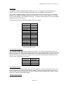
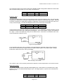
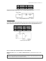
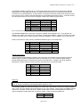
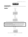
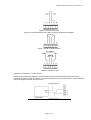
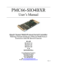
Anville Instruments
Series 425SB Data Acquisition System
Hardware User Manual
(QP10)
June 2004 Issue 2
Anville Instruments Ltd.,
Unit 19, Pegasus Court,
North Lane,
Aldershot, Hants, GU12 4QP
Tel. 01252 351030
Fax. 01252 323492
NOTICE
The contents of this manual are liable to change without notice. Whilst every effort has been made to
ensure the accuracy of this manual, Anville will not be responsible for any errors and omissions or their
consequence.
Windows and MS-DOS are registered trademarks of Microsoft Corporation.
COPYRIGHT
This documentation and the software described in it are copyrighted with all rights reserved.
Under copyright laws, neither the documentation nor the software may be copied, photocopied,
reproduced, translated, or reduced to any electronic medium or machine readable form, in whole
or in part, without the written consent of Anville Instruments. Failure to comply with this condition
may result in prosecution.
S425SB Hardware User Manual. June 2004. Iss. 2
CONTENTS
PART I:
INTRODUCTION TO THE SERIES 425SB
PART II:
SERIES 425SB CONFIGURATION
PART III:
CONNECTING THE SERIES 425SB TO YOUR COMPUTER
PART IV:
SPECIFICATIONS
Page 2 of 16
S425SB Hardware User Manual. June 2004. Iss. 2
AN OVERVIEW OF THIS USER MANUAL
This manual is divided into 4 parts. Part I introduces you to the SERIES 425SB. Starting with Part II, the
manual shows you how to configure and operate the unit. After mastering the system, you can use the
manual as a handy reference. When you need help with a specific problem, turn to the appropriate area of
the manual that describes that part of the system.
To give you an idea of the manual’s layout, here is a description of each part of the manual:
• Part I describes the hardware for both the SERIES 425SB and the computer system.
•
Part II describes system hardware configuration and tells you how to connect the different types of
sensors.
• Part III tells you how to connect the SERIES 425SB unit to your computer.
•
Part IV provides specifications for the SERIES 425SB equipment.
Page 3 of 16
S425SB Hardware User Manual. June 2004. Iss. 2
PART I: INTRODUCTION TO SERIES 425SB
OVERVIEW
Welcome to the SERIES 425SB Data Acquisition Unit which provides 16 general purpose analogue inputs,
8 digital inputs and 8 digital outputs. The units operate in conjunction with a wide variety of bespoke or
SCADA computer based software packages. The SERIES 425SB is connected to a compatible computer
system which provides the SDADA software operating environment working under Windows 3.x, Windows
for Work Groups, Win’95/98 and Windows NT
The compact hardware provides thermocouple and general purpose analogue inputs, digital inputs and
digital outputs. Connection to a computer, using the supplied cable, is made via an RS422/423 serial link.
An additional RS422/423 connector allows you to ‘daisy-chain’ two SERIES 425SBs together if more
analogue inputs are needed. The SERIES 425SB’s internal microprocessor converts all inputs into their
correct engineering units for transmission to the host computer.
COMPATIBLE COMPUTER SYSTEM
Your computer system should comprise a system unit, SVGA monitor, keyboard and printer. The system
unit must be have 486 processor, a 100Mbyte hard disk with at least 30 Mbytes free for system software
and 8Mbytes of RAM. A reasonably sized hard disk is necessary for storing SERIES 425SB data files if
logging for long periods.
System Unit and Memory
The system unit is the large box component of the computer. The back of the unit supports all ports used
for connecting your peripheral equipment including the SERIES 425SB. Your SERIES 425SB will plug into
to either COM1 or COM2 serial ports using the supplied data cable but on some system units the mouse
could be using COM1, which means using COM2 instead. It is also possible that COM2 is a 25-pin
connector. In this case you’ll need a 25-pin (female) to 9-pin (male) adapter. A printer port is also
required.
The system unit houses the PC's main microchip and the computer's internal memory as well. The
memory has several names. You commonly hear it referred to as RAM (Random Access Memory).
The SVGA Monitor
The television-like screen is called the monitor. The monitor is one place where graphical data and
spreadsheet data will be sent for viewing. Your monitor plugs into the back of your system unit .
The Printer
Your printer provides a more permanent way of recording your SERIES 425SB's system results. It can be
used to provide hard copies of on-screen information and spreadsheet data. The printer can be described
as the `typewriter' of a SCADA logging system. The printer plugs into the parallel port at the back of the
system unit.
The Keyboard
The keyboard plugs into the back of your system unit. Most of the keys are the same as a standard
typewriter. The letters and numbers in the large centre of the keyboard produce the characters that you
type on-screen. In the main you will use only these keys in conjunction with using your mouse.
PART II: SERIES 425SB CONFIGURATION
Page 4 of 16
S425SB Hardware User Manual. June 2004. Iss. 2
Box Address
Your SERIES 425SB is supplied with its’ address set to zero. An address is set by the positions of
switches 1 to 4 of the UNIT CONFIGURATION switch array. See SERIES 425SB side panel.
If more than one SERIES 425SB is to be used on the computer port, it will be necessary to alter switch
settings of any additional SERIES 425SBs thus providing each one with a unique address. For example,
box 1 will have address 0, box 2 address 1 and so on. To initialise switch settings, power to the SERIES
425SB must be turned off then on.
The table below provides configuration address and switch settings.
Switch setting
1 2 3 4
on on on on
off on on on
on off on on
off off on on
on on off on
off on off on
on off off on
off off off on
on on on off
off on on off
on off on off
off off on off
on on off off
off on off off
on off off off
off off off off
Unit address
0
1
2
3
4
5
6
7
8
9
10
11
12
13
14
15
Unit Configuration Table
Communication Baud Rate
Your SERIES 425SB is supplied with baud rate set to 9600. If you need to change the baud rate, use
switches 5 and 6 of the UNIT CONFIGURATION switch array. The following table gives switch settings for
specific baud rates. To initialise switch settings, power to the SERIES 425SB must be turned off then on.
Please note that whichever baud you configure, you must also set the same baud in Windows Control
Panel to match. See below how to do this.
Switch settings
5 6
on on
off on
on off
off off
Baud rate
1200
2400
9600
19200
Communication Format
The communication format is fixed and will consist of 8 data bits, 1 stop bit, no parity, flow control- none.
Please note that if you are not using the SERIES 425SB’s software it is very important that you set the
communication format and baud rate for the chosen serial port using WINDOWS Start, Settings, Control
Panel before operating the SERIES 425SB.
Analogue Outputs (option)
Page 5 of 16
S425SB Hardware User Manual. June 2004. Iss. 2
Two analogue outputs may be factory fitted to the SERIES 425SB. Configuration details are shown below
with connections being made via a 4- pin plug in terminal block.
Pin no.
1
3
Signal name
anout ground
anout ground
Pin no.
2
4
Signal name
anout 2
anout1
Frequency Input
The Series 425SB provides inputs for measuring both pulse count and frequency (Hz). The type of input
configuration is dependent on the type of signal output from equipment connected to the logger. Selection
of counter or frequency is made during software configuration. Connections to the logger are made via a
4-way screw block plug. The table and diagrams below show pin and input connections.
Pin No.
1
3
Signal Name
+5V output
trig. level
Pin No.
2
4
Signal Name
input
ground
A logic level/uni-polar input with a signal level of between 0V to 5V (CMOS/TTL) would (generally) use the
connections shown in the Logic Level Input Circuit diagram. 0V to 2.4V ±100mV = logic 0; 2.6 ±100mV to
5V = logic 1. Pulse count input has a range of 0 to 65535 counts. Counts are not cumulative; each ‘new’
count will replace the previous count.
Logic Level Input Circuit
An AC signal/bi-polar input, from 0 to 65Khz, would (generally) be measured using the Zero Crossing
Level circuit connections with voltage levels from 100mV peak-to-peak to 10V peak-to-peak. Voltage
levels below 100mV will not be ‘seen’ by the logger.
Zero Crossing Level Circuit
The +5VDC on pin 1 can be used to power devices where the current requirement is not more than 5mA.
Digital Inputs (digin)
The SERIES 425SB provides 8 optically isolated digital inputs. With reference to the table below, digin
signals on pins 2-5 are measured with respect to pin 1 and digin signals on pins 5-8 are measured with
respect to pin 6.
Pin
1
Signal name
ground
Pin
6
Page 6 of 16
Signal name
ground
S425SB Hardware User Manual. June 2004. Iss. 2
2
3
4
5
digin 1
digin 2
digin 3
digin 4
7
8
9
10
digin 5
digin 6
digin 7
digin 8
The input connector provides access to one end of the LED of an optical isolator with a 4K7 series
resister to limit current. Connections are via a 10-pin plug supplied with the unit.
A typical digital input circuit
Digital Outputs (Digout)
The SERIES 425SB provides 8 digital outputs. These are open collector transistor type outputs capable of
directly driving relays. With reference to the table below, digout on pins 2-5 are with respect to pin 1 and
digout on pins 5-8 are with respect to pin 6. Connections are via a 10- pin plug supplied with the unit.
Pin no.
1
2
3
4
5
Signal name
ground
digout 1
digout 2
digout 3
digout 4
Pin no.
6
7
8
9
10
Signal name
ground
digout 5
digout 6
digout 7
digout 8
A typical digital output circuit
PART III: CONNECTING THE SERIES 425SB TO YOUR COMPUTER
IMPORTANT NOTE: please refer to PART IV: SPECIFICATIONS if you do not intend using the cable
supplied.
NOTE: Pins 6 and 8, pins 7 and 8 of the ‘D’ type plug are no longer linked for RS232 or RS422
operation. Units are factory set for the required protocol. However, cables with links fitted can still be
used. Pin configuration details are retained for reference.
Page 7 of 16
S425SB Hardware User Manual. June 2004. Iss. 2
The SERIES 425SB is supplied with a 2 metre length cable (which meets the requirements of RS232)
fitted with 9 pin 'D' type plug and socket. The system requires transmit (Tx), receive (Rx) and ground
connections for most applications, so these are the only signal connections made in both plug and socket.
Pins 6 and 8 or pins 7 and 8 are linked depending on serial data transmission protocol. Links are made in
the cable plug end that is connected to the logger. Cable wiring details are given below.
Pin
2
3
5
6
7
8
Pins 1,4 and 9 are not used.
Signal name
Tx
Rx
signal ground
RS422 link
RS423 link
+5V
Signal direction
to Computer
from Computer
Wire
white
black
screen
Linked to pin 8
Linked to pin 8
The SERIES 425SB has two serial port connectors, SERIAL IN and SERIAL OUT. As a general rule,
SERIAL OUT will be connected to your computer in a single unit installation. Where a second unit is used,
it will be connected into the system by 'daisy chaining' the SERIAL IN to the SERIAL OUT of the first unit.
Cable connections for ‘daisy chaining’ a SERIES 425SB are given in the table below.
Pin
2
3
5
6
7
8
Signal name
Tx
Rx
Signal ground
RS422link
RS423 link
+5V
Signal direction
to next 425SB
from next 425SB
Wire
white
black
screen
Linked to pin 8
Linked to pin 8
RS422 Transmission
If the overall line length (distance) between your PC and the second daisy-chained logger exceeds 30
metres (approx. 65 feet) an RS422 serial card must be fitted to your PC to maintain signal integrity.
RS422 signal titles and pin connections are given in the table below. In addition the serial cable link
between pins 7and 8 must be removed and pins 6 and 8 linked. See previous table.
Pin
1
2
3
4
5
Signal
Name
Txb
Txa
Rxa
Rxb
ground
Signal Direction
to computer
to computer
from computer
from computer
Power Up
Note: in order to comply with European EMC legislation the Series 425SB must be connected to mains
earth. No action is necessary if the supplied mains adapter is used.
The SERIES 425SB is dc powered requiring +5V at 0.5A and +24V at 0.2A. The unit is normally supplied
with a 230V AC mains adapter which will provide correct input voltages. Power enters the SERIES 425SB
via the 4 pin connector on the rear panel. Where several units are to be mounted within an enclosure it
may be beneficial to power them from a Common supply. Power connection details are:
Pin
1
Signal name
Earth
Page 8 of 16
S425SB Hardware User Manual. June 2004. Iss. 2
2
3
4
0V
+5V
+24V
Front Panel Connection Details
All front panel connections are made through convenient solderless screw 6-way terminal blocks supplied
with the SERIES 425SB.
Analogue Inputs
Figure 1 Voltage input
Figure 2. Current loop input: 4 to 20mA (powered by transmitter or other external source)
CAUTION
Where thermocouples are used involving fluids or condensing gases, for example with Autoclaves, they must be
connected to the data logger in one of two ways:
1. At a point lower than the logger, remove at least 2.5cm of insulating material from the thermocouple wire.
2. Make thermocouple connections to the logger via flying leads, either below logger level or at a distance of 0.5
metres, with an in-line cable mounting socket attached.
Both of these methods ensure that any liquids migrating up the thermocouple wire due to the capillary effect,
escape before reaching the logger. Serious damage to the logger will result if liquid is allowed to enter.
Figure 3. Current loop input: 4 to 20mA (powered by Series 425SBSB)
Page 9 of 16
S425SB Hardware User Manual. June 2004. Iss. 2
Figure 4. Thermocouple input
Note: do not fit link between pins 4 and 5 if using grounded thermocouples
Figure 5. Pt100 or resistive inputs
Figure 6. Transducer input
Transducer Connections - 4-20mA output.
Please note that this wiring diagram is an alternative to Figure 2 and should be used if a transducer,
connected as Figure 2 does not respond. The example shows how you would connect a 2-wire transducer
to the unit using an external +24V DC source.
Page 10 of 16
S425SB Hardware User Manual. June 2004. Iss. 2
PART IV: SPECIFICATIONS
DATA LOGGER
Construction
The SERIES 425SB data logger is constructed as a metal box formed by 2 U-shaped sections. A bottom
box section forms the mount for printed circuit boards (PCB). All components are mounted on the PCBs.
A top box section locates over the bottom section, allowing access to connectors and switches and is
secured into position using 4 M3x6mm screws. Four rubber feet are screwed to the bottom.
Dimensions: 269mm long, 150mm wide, 95mm deep (including feet).
Connectors
• 16 inputs (combinations of thermocouple and general purpose connectors).
• 2 RS423 ports
Page 11 of 16
S425SB Hardware User Manual. June 2004. Iss. 2
•
•
•
•
•
1 digital input
1 digital output
1 analogue output (option)
1 power input
1 frequency input
Switches
• 4 unit configuration
• 2 baud rate
Mounting and Ventilation
To mount a logger, remove rubber feet and use the same screw locations. Maximum screw length
penetration is M3x4mm. It is dangerous to exceed the recommended penetration length as damage to
internal components could occur.
The logger requires no special ventilation requirements.
Cleaning
Loggers are easy to clean. Use a non-abrasive or foam cleaner.
ANALOGUE INPUTS
Direct Voltage and Current
Range
±10mV
±100 mV
± 1V
± 10v
4-20mA
Resolution
1uV
10 uV
100 uV
1 mV
0.01%
Accuracy
±0.02%
±0.02%
±0.02%
±0.02%
±0.02%
Thermocouples
Input range °C
-200 to +400
-100 to +200
-200 to +1200
-100 to +200
-100 to +1100
0 to +1300
-100 to +1000
0 to +1700
0 to +1700
0 to +1800
Input function
T thermocouple
T thermocouple
K thermocouple
K thermocouple
J thermocouple
N thermocouple
E thermocouple
R thermocouple
S thermocouple
B thermocouple
Resolution °C
0.1
0.01
0.1
0.01
0.1
0.1
0.1
1
1
1
Page 12 of 16
Accuracy °C*
± 0.5
± 0.25
± 0.5
± 0.5
± 0.5
± 0.5
± 0.5
±4
±4
±4
S425SB Hardware User Manual. June 2004. Iss. 2
* Note: accuracy includes cold junction error when using thermocouple sockets but not when using general
purpose sockets.
PT100 - 100 ohms @ 0°C, 4 wire connection
Range °C
-100 to +600
-100 to +200
Resolution °C
0.1
0.01
Accuracy °C
+/-0.5
+/-0.2
Pressure transducer/load cell
Range
±10 mV
±100 mV
±1V
±10 V
Resolution
1 uV
10 uV
100 uV
1 mV
Accuracy
±0.02%
±0.02%
±0.02%
±0.02%
Signal conditioning
For thermocouple, PT100 and pressure transducers.
Transducer energisation
• For PT100: switched constant current of 1mA.
• For pressure transducer/load cell: switched constant voltage of 10V.
• For 4-20mA current loop: switched constant voltage of 24V.
Input switching
Reed relay - 3 pole switching.
Engineering units
As appropriate or selectable:
mV, V, mA, C, % ( as appropriate or selected).
Scan speed
8-16 inputs per seconds
Configuration using X-425SB software.
Serial link
RS232 or RS422. Choice dependant on cable length.
Cable length
Maximum cable length for RS232 operation is approximately 30 metres.
Maximum cable length for RS422 operation is approximately 1.5 kilometres.
To avoid electrical interference the serial cable should be installed away from other cables particularly
mains voltage cables. Ideally the serial link should be installed in it’s own trunking
Cable Type
For runs of up to 30 metres: two pair, overall foil shielded, 24 AWG, polyethylene insulated, PVC
screened.
Type: 0S2P24, UL style 2464 obtainable from Farnell Electronic Services (FES)
For runs of up to 1.5 kilometres: two pair, overall foil shielded, 24 AWG, polyethylene insulated, PVC
screened.
Page 13 of 16
S425SB Hardware User Manual. June 2004. Iss. 2
Type: FB0S2P24, UL style 2919 obtainable from FES.
Type 2, UL style 2493 obtainable from RS Components, part no. 368-738.
Note: only 2 wires are used: BLACK from red/black twisted pair and WHITE from white/black
twisted pair.
Baud rate
Four baud rates are available: 1200, 2400, 9600,19200.
Daisy-chained linked loggers
Maximum number of loggers that can be daisy-chained is 16
Environmental Operating Range
0° C to 40° C.
Power supply
+5V @ 0.5 Amps and +24V @ 0.25 Amps.
OTHER INPUTS/OUTPUTS
Frequency input
Optically isolated frequency and pulse count.
Frequency range 0 to 65khz or 0-65535 counts (software configured).
Signal level 100mV pk-pk to 10V pk-pk or CMOS.
Digital inputs
Voltage free contact, TTL or CMOS optically isolated.
Digital outputs
Open collector transistor, max sink current = 500mA. Max switching voltage = 24VDC.
Analogue outputs
Isolated 0 to 10V; accuracy ±0.1%.
COMPUTER
•
•
•
•
•
•
•
•
Processor type:
Processor speed:
Machine memory (RAM):
Display type:
Hard-disc size:
Pointer device:
Serial ports:
Printer/parallel ports:
486SX/DX
33MHz
8Mb
VGA
100Mb
Mouse, tracker ball (some laptops).
2.
1
POWER SUPPLY SPU 41-16
The power supply is an AC/DC switching power supply providing 30 watts of continuous output power. The
supply is enclosed in plastic case with IEC320 inlet connector to mate with interchangeable mains cable
for world-wide use. This model complies with CUL, TUV, and CE requirements.
Input
Voltage:
Frequency:
90 to 264 VAC
47 to 63Hz
Page 14 of 16
S425SB Hardware User Manual. June 2004. Iss. 2
Current:
1.2A (rms) @ 230VAC
Inrush current: <60A peak at 230VAC cold start
Output
Voltage:+5V DC @ 3.0A max, ripple and noise 50mV
Voltage: +24V DC @ 1.0A max, ripple and noise 150mV
Power range: 0 to 30 watts
Over voltage protection: 110-140% of nominal output voltage
Over load protection: pulsing mode, auto recovery.
Line regulation: +/- 0.5% max at full load
DC pin chart
Wire
Screen
Black
Brown
Green
Pin
1
2
3
4
Voltage
earth
0V
+5V
+24V
Environmental
Operating temperature: 0 to 30°C @ 100% load; 0 to 40°C @ 60% load
Relative Humidity: 20 to 90%
General
Efficiency:
Hold-up time:
Withstand voltage:
Insulation resistance:
EMC standards
Safety standards
78% min at 30W output
12 msec min
I/P-O/P:3KVA, I/P-FG: 1.5KVA, 1 min
10 Mohm min from output to ground
EN55022, IEC801-2, 3, 4
UL 1950
CSA C22.2 NO.234
Notes:
Page 15 of 16
S425SB Hardware User Manual. June 2004. Iss. 2
Page 16 of 16