1
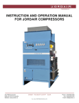
J O R D A I R COMPRESSORS INC. INSTRUCTION AND OPERATION MANUAL FOR JORDAIR COMPRESSORS Jan 1st, 2006 JORDAIR - “RELIABILITY & SAFETY” - BAUER 101-7950 Huston Road, Delta, B.C., V4G 1C2 Web site www.jordair.ca Doc. Jordair COMPRESSOR-MANUAL-2006 Tel: 604-940-8101 Fax: 604-940-8131 J O R D A I R COMPRESSORS INC. JORDAIR GENERIC INSTRUCTION AND OPERATION MANUAL This Jordair Compressor Operators Manual is prepared for your reference, the user’s safety and to ensure the correct operation of the compressor system. For the operator’s safety, it is important that this entire manual be read and followed!!! WARNING! Failure to operate and maintain the compressor system according to this instruction book can result in unacceptable air quality and be hazardous to the operator. These practices will also void the warranty. GENERAL NOTE: The operations manual is designed to cover all of the options and features available on the standard Jordair Compressor Inc. breathing air compressor systems. As such, it is quite normal that some of the features listed may or may not be on the customer’s specific compressor model. Please review the complete manual to familiarize yourself with all aspects of the compressor system. Be sure to pay specific attention to those items, which apply, directly to your compressor system. The Bauer compressor block manual and parts list is the supplementary manual for the specific compressor model and system. Please contact the factory for additional detailed technical clarification or any other specific information required: HEAD OFFICE AND MANUFACTURING: Jordair Compressors Inc. #101-7950 Huston Rd Delta, BC V4G 1C2 Toll Free: (800) 940-8101 Fax: (604) 940-8131 Web site: www.jordair.ca JORDAIR - “RELIABILITY & SAFETY” - BAUER 101-7950 Huston Road, Delta, B.C., V4G 1C2 Web site www.jordair.ca Doc. Jordair COMPRESSOR-MANUAL-2006 Tel: 604-940-8101 Fax: 604-940-8131 J O R D A I R COMPRESSORS INC. WARNING! HIGH PRESSURE UNITS Never operate a high-pressure compressor with the inter-stage or final safety relief valves removed and plugged, or if the safety valves are adjusted above the factory set range. Tampering with inter-stage relief valves can result in an “Explosion Failure” of a cylinder or cooler tubing. High pressure air has Tremendous Kinetic Energy and should be treated with the utmost caution. JORDAIR - “RELIABILITY & SAFETY” - BAUER 101-7950 Huston Road, Delta, B.C., V4G 1C2 Web site www.jordair.ca Doc. Jordair COMPRESSOR-MANUAL-2006 Tel: 604-940-8101 Fax: 604-940-8131 J O R D A I R COMPRESSORS INC. TABLE OF CONTENTS Safety Facts for setting up your Compressor ..............................................................................1 Preparation for Compressor Service ............................................................................................2 Intake Filters ..� 2 Compressor Description ................................................................................................................3 Air Flow ..........� 3 Maintenance Timetable .................................................................................................................4 Type of Oil ......� 4 Oil Change Procedure ...................................................................................................................5 To Prepare the Compressor for Prolonged Storage ....................................................................5 Reactivating The Compressor Unit …………………………………………………………….5 Lubrication System ........................................................................................................................6 Compressor Oil Pump Drive .........................................................................................................6 Oil Pump Drive Service .................................................................................................................7 Compressor Oil Pump ...................................................................................................................7 Oil Pressure Regulator ..................................................................................................................7 Initial Trial Run of the Compressor .............................................................................................8 Pressure Relief Valves ....................................................................................................................8 Valve Heads ....� 9 Valve Head Maintenance ...............................................................................................................9 Cylinder Removal ........................................................................................................................10 JORDAIR - “RELIABILITY & SAFETY” - BAUER 101-7950 Huston Road, Delta, B.C., V4G 1C2 Web site www.jordair.ca Doc. Jordair COMPRESSOR-MANUAL-2006 Tel: 604-940-8101 Fax: 604-940-8131 J O R D A I R COMPRESSORS INC. Piston Final Stage.........................................................................................................................10 Automatic Drain System .............................................................................................................10 Automatic Drain Operation ........................................................................................................10 Service of the Automatic Drain…………………………………………………………10-11-12 Jordair Compressor Controls .....................................................................................................12 Manual-Off-Auto Switch .................................................................................................12 Auto Mode ........................................................................................................................13 Start Switch ......................................................................................................................13 LOP Fault Indicator Light and Audible Alarm ............................................................13 HAT Fault Indicator ........................................................................................................13 Silence Button for the Audible Alarms...........................................................................14 Power on Light .................................................................................................................14 Initial Operating Sequence ........................................................................................................14 Compressor Air Pressure Switch ................................................................................................15 Compressor Oil Switch…………………………………………………………………….…...16 Service Of the Final Oil and Water Separator………………………………………...16-17-18 Service Of the Pressure Maintaining Valve…………………………….………….……...18-19 Note to Operators……………………………………………………………….…..……...19-20 Trouble Shooting………………………………………………………………….………...20-21 Recommended Procedures for Testing Pure Air…………………………………………….21 Filter Information for 5000 PSIG Systems…………………………………………………..22 Filter Information for 6000 PSIG Systems…………………………………………………..23 Daily SCBA Log Compressor Service Log SUPPLEMENTRAY: Bauer Block Instruction Manual and Spare Parts Catalogue JORDAIR - “RELIABILITY & SAFETY” - BAUER 101-7950 Huston Road, Delta, B.C., V4G 1C2 Web site www.jordair.ca Doc. Jordair COMPRESSOR-MANUAL-2006 Tel: 604-940-8101 Fax: 604-940-8131 J O R D A I R COMPRESSORS INC. Safety Facts for Setting Up Your Compressor Setting up in a Closed Room A compressor is an air-cooled machine, and since air under compression increases in temperature, it is imperative that the compressor be installed with adequate ventilation. The machine should be placed at least 12” away from any wall. Air should be available from two directions within the room, the openings in each wall being in excess of six square feet, preferably with one opening close to the floor and the other close to the ceiling. If flowing ventilation is not available, a fan must be used to remove the heated air. Follow the installation guidelines in the Bauer Compressor Installation Manual IH-E 11/94 The compressor should never be operated with an ambient room temperature in excess of 40°C. The air must be free of poisonous gases and exhaust gases (such as flue gases, solvent fumes, paint fumes, engine exhaust etc.) NOTE: When setting up a compressor station in a sub-grade or basement location, always ensure that the intake air supply is from an external location where the ambient air is as pure as possible. NOTE: Do not place the compressor air intake hose in a basement window; which is set below ground level or on the same level with the sidewalk. Danger to Life Exists, due to the possible contamination of vehicle Exhaust gases! Setting up in the Open Air For gasoline or diesel driven units it is important that pure air only is sourced for the compressor intake. Set up the unit in so that the engine exhaust is down stream of the wind direction, so the combustion gases are carried away from the compressor unit and the air intake. Jordair recommends the mounting of an intake hose of at least 7.5 feet in length to the compressor intake filter with pre-filter. The pre-filter is to be placed at a height of 5 feet. This method of compressor set up provides a safe distance between the outlets of the exhaust gases and air the compressor intake air supply. If there is a change in the wind direction, turn the unit correspondingly. Operate a unit with a diesel or gasoline engine in the open air; never operate an engine driven compressor in a room being completely or partially closed. JORDAIR - “RELIABILITY & SAFETY” - BAUER 101-7950 Huston Road, Delta, B.C., V4G 1C2 Web site www.jordair.ca Doc. Jordair COMPRESSOR-MANUAL-2006 1 Tel: 604-940-8101 Fax: 604-940-8131 J O R D A I R COMPRESSORS INC. An engine driven compressor can be operated within an enclosed or partially enclosed area if the exhaust is piped outside of the space through a wall and the compressor intake air is sourced at a high elevation away from the exhaust gas contamination. Ensure that vehicles with running engines are not within 50 meters of the intake inlet unless the compressor is integrated into the vehicle and operates off the vehicle engine or generator system. On truck mounted systems ensure the air intake is located well away and elevated above the source of the vehicle exhaust gases. Do not run the unit near an open fire (flue gases). Preparation for Compressor Service 1. Open frame units, these compressors are readily accessible and will not require the removal of frame enclosing components for routine service. 2. Enclosed units, the Ultra-Silent and Integra compressors require panel removal before service work is performed. Lift the latches out and turn to release the panel, and then remove the front, rear and top panels from the unit. This will expose the compressor unit for service. The lower panel must be removed to adjust the drive belts. Intake Filters & Extended Intake Piping The air intake filter is a dry paper type micron element, effective to 5-micron filtration of particulate matter. This cartridge can be easily replaced without the use of tools. If an intake extension is to be attached to the intake filter, use a short section of non-collapsible flexible hose. This flexible hose will connect the compressor to the wall mounted intake pipe. The flex hose will absorb vibration between the compressor and the air intake extension pipe. The plastic wall-mounted intake pipe is to have a minimum diameter of two inches for up to 25 feet of length. This is based on a flexible intake hose length of 5 feet. The plastic intake pipe is to be increased by ½” increments in diameter for every additional 25 feet of distance from the compressor. Discharge Piping All compressor installation piping is under the Provincial Boilers & Pressure Vessels jurisdiction and installed tubing and fittings must have CRN registration and be installed by a B&PB licensed and registered contractor. JORDAIR - “RELIABILITY & SAFETY” - BAUER 101-7950 Huston Road, Delta, B.C., V4G 1C2 Web site www.jordair.ca Doc. Jordair COMPRESSOR-MANUAL-2006 2 Tel: 604-940-8101 Fax: 604-940-8131 J O R D A I R COMPRESSORS INC. Compressor Description The air compressor is a multi-stage, air cooled, single acting and reciprocating unit, designed to deliver a final discharge pressure depending on the specific model of unit of 5000 psig, 6000 psig or 7250 psig. Lower pressure shut down is set on the final operating pressure switch shut down set point. Note: The standard design of compressor is for 5000 or 6000 psig service and special units are offered for 7250 psig filling applications. Lubrication is by splash and full flow filtered oil pressure injection to the final free floating piston. The compressor operates with an optimum oil pressure range from 50 to 75 psig depending on the model. The oil pump pressure regulator on all units automatically regulates the compressor oil pressure. Air Flow The process airflow is subjected to heat generation as part of the thermal temperature increase when air is subjected to the compression stages of the compressor. The inter-stage coolers are designed to remove most of the heat and the separators collect the accumulating moisture generated during compression. The airflow begins when the compressor crankshaft rotates and the first-stage piston draws the ambient air through the micron intake filter and the suction valve into the first stage cylinder. This air is compressed by the first stage piston and expelled through the discharge valve and travels via the inter-cooler to the second stage. It is necessary to cool the air to nearly to the ambient temperature to reduce component wear and prevent combustion of the lubricating oil and production of carbon monoxide. The Bauer block achieves the optimum in cooling efficiency with all inter-coolers and cylinders located in the direct airflow path of the cooling fan. The air enters the second stage through the suction valve and is compressed by the piston. The compressed air after passing through the discharge valve is cooled by an inter-cooler and any oil droplets or an inter-stage separator removes liquid moisture. On the four stage compressors this process is repeated in the third stage and the air is again cooled and liquid oil and moisture is removed at a separator prior to entering the fourth stage. In five stage compressors the process is repeated on the fourth stage. The compressed air leaving the final stage is cooled to approximately 5 to 8°C above ambient temperature and remaining liquids are collected in the final oil/water coalescing separator. The collected moisture and oil droplets can be drained manually or by an automatic drain device into the condensate collection container for manual draining of accumulated liquids. The process air is pre-cleaned to 5 microns by a micro-fibre or sintered element in the oil and JORDAIR - “RELIABILITY & SAFETY” - BAUER 101-7950 Huston Road, Delta, B.C., V4G 1C2 Web site www.jordair.ca Doc. Jordair COMPRESSOR-MANUAL-2006 3 Tel: 604-940-8101 Fax: 604-940-8131 J O R D A I R COMPRESSORS INC. water separator and passes out through a check valve. This one-way check valve stops the purified air from flowing back into the oil and water separator. The process air is then dried in a drying cartridge and purified to eliminate oil and hydrocarbons. A CO catalyst removes any CO and the activated carbon completes the process of purifying the air to the CSA breathing air standard. Special filters and purifications systems can be installed to remove any undesirable component in the compressed air. The final pressure-maintaining valve is set at approximately 2800 PSIG to ensure efficient operation of the filter system. Contact Jordair Compressor directly for specialized technical assistance on nonstandard applications. Maintenance Timetable A logbook is an ideal means of maintaining running time and dates of service. The first oil change is recommended after reaching 25 hours of running time or within 3 months, whichever occurs first. Each additional oil change is to take place after 500 hours of operation or every 6 months. (It is recommended the compressor be run for approximately 30 minutes to warm the oil prior to draining). Check all mounting bolts, compressor bolts and electrical connections prior to placing a compressor in service and also at 100 hours to avoid any problems related to transport vibration or other reasons. Type of Oil The use of the correct oil is necessary to maintain compressor reliability and warranty. The compression loading is over three, four or five stages, which neither stresses the oil mechanically nor creates thermal excesses. It is, however, recommended that only first class grades of oil be used. To ensure reliable compressor service and warranty, use those oils as prescribed by Jordair, which have the smallest inclination to produce carbon and guarantee protection against corrosion. The recommended oil is Jordair part number J-EP-65 compressor oil. Contact Jordair for an alternate oil selection if it is impractical to obtain the Jordair oil at the compressor location. Synthetic oils are also available for use in breathing air compressors to increase the operating life when the compressor is subject to heavy-duty cycles and high ambient temperature condition. JORDAIR - “RELIABILITY & SAFETY” - BAUER 101-7950 Huston Road, Delta, B.C., V4G 1C2 Web site www.jordair.ca Doc. Jordair COMPRESSOR-MANUAL-2006 4 Tel: 604-940-8101 Fax: 604-940-8131 J O R D A I R COMPRESSORS INC. Oil Change Procedure If the recommended operating hours, between changes, are not reached in six months time, the oil is to be changed to avoid internal corrosion. Remove the drain plug and open the drain valve, then drain the oil into a container for disposal. The oil is to be drained while the compressor is still warm. On compressor units with magnetic plugs, remove and clean all particulate. To re-fill the oil, close the valve and replace the drain plug then remove the oil cap and add the oil slowly to the correct level on the sight indicator glass, older models may have a oil level dipstick. Caution: Never over-fill the compressor with oil. If the compressor is overfilled, drain the excess oil to the correct level on the sight level glass or dipstick. Start the unit and check the sight glass or oil pressure gauge to ensure the lubricating oil system is operating correctly. If the oil pressure fluctuates then bleed any air at the pressure gauge or oil regulator. Always bleed at the highest point to remove all air from the pressure lubrication system. To Prepare the Compressor for Prolonged Storage First proceed as above and perform the oil change. Next, remove the intake filter housing and operate the compressor with the drain cocks open, slowly pour approximately 20 ml. of oil into the cylinder intake hole on the first stage while the inter-stage drain valves are open. Stop the compressor, close all drains, replace and seal the compressor intake housing. Now the compressor unit is ready for storage. Reactivating The Compressor Unit Remove the dust cap from the inlet port and replace the intake filter. Check the oil level of the compressor. Check the motor/engine according to the manufacturer’s instructions. Only applicable for units equipped with a filter system: open the purifier and change all filter cartridges. Operate the compressor with open filling valves or outlet valve for approx. 5 minutes. Check the oil pressure on the pressure gauge. If there is any fault, check the lubrication of the compressor. JORDAIR - “RELIABILITY & SAFETY” - BAUER 101-7950 Huston Road, Delta, B.C., V4G 1C2 Web site www.jordair.ca Doc. Jordair COMPRESSOR-MANUAL-2006 5 Tel: 604-940-8101 Fax: 604-940-8131 J O R D A I R COMPRESSORS INC. After 5 minutes, close the filling valves or the outlet valve and run the unit up to final pressure or until the final pressure safety valve blows. To check the final safety valve override the pressure switch, if installed on the unit. Check the inter-pressure safety valves for leakage. Establish the cause of any fault by identifying it in the general information from the trouble–shooting table, section 19, and remedy. The compressor is now ready to return to normal service. Lubrication System The final stage piston is pressure lubricated by an injection pump with a nominal pressure of 50 to 75 psig. The lubricating oil is pumped through an in-line filter to the pressure regulator mounted on the oil pump housing. The lubricating oil is regulated and injected on the lower part of the floating piston when it is in the top dead centre position. The oil enters into the clearance between the floating piston and the cylinder sleeve. The high-pressure oil lubricates the piston and rings and minimizes compression blow by. The excess oil from the regulator flows back to the crankcase through a return line. The drive gear atomises the oil and the mist lubricates the piston rings and rod bearing. The crank and main bearings are splash lubricated when the crankshaft counter weight enters the oil. The first stage cylinder receives additional lubrication from the crankcase breather pipe, which is connected to the intake port of the cylinder head. Compressor Oil Pump Drive New Bauer 2004 production blocks series IK100II to IK18.1II; the compressor oil pressure of 5bar (72psig) is developed by a low revving gear type oil pump. The oil is pumped up through a final oil filter element. The filter element is to be changed every time the oil is changed to ensure correct service procedures. Oil Pump Drive Service On the 2004 series compressors the oil pressure is not adjustable, if the oil pressure drops below the minimum of 45 psig replace the oil-regulating valve as an assembly, part number 81050. If the oil pressure is still not correct then the pump must be replaced. An oil pump assembly is replaced under part number N24585. The oil filter element number for replacement is N25326. Review the specific model parts list and Bauer manual for service procedures. JORDAIR - “RELIABILITY & SAFETY” - BAUER 101-7950 Huston Road, Delta, B.C., V4G 1C2 Web site www.jordair.ca Doc. Jordair COMPRESSOR-MANUAL-2006 6 Tel: 604-940-8101 Fax: 604-940-8131 J O R D A I R COMPRESSORS INC. Initial Trial Run of the Compressor On start-up, a clicking or knocking sound will be heard from the final stage of the compressor. This is a normal condition, produced by the free-floating piston tapping the guide piston in the final stage. This noise will only last until a counter pressure is built up, usually within 15 to 20 seconds. If the knocking sound continues check for inter-stage leaks, open drain cocks or a defective automatic drain system seat or solenoid valve. Follow the repair procedures as outlined for the specific component in this manual. Pressure Relief Valves As required by ASME and Boiler and Pressure Vessel, each stage of compression is provided with a spring-loaded type pressure relief valve factory set and sealed to operate at a suitable pressure to protect the individual stages of the compressor. The pressure relief valves are set high enough to allow for the momentary pressure surges, which occur as a cylinder discharges. The final discharge pressure relief valve is located on top of the final oil and water separator. The final separator is usually mounted on the same part of the compressor frame as the purification chambers. Safety valves between stages protect the prior cylinder and also indicate a compressor inlet or exhaust valve malfunction when the safety valve is venting. For example: a final stage inlet or exhaust valve leak will cause excessive pressure rise between it and the preceding stage, opening the third stage relief valve. The over pressure that is built up by the final stage and not pumped onward in the system is vented safely to atmosphere by the relief valve. Caution! Never adjust inter-stage relief valves; this can cause failure of a cylinder or intercooler resulting in a possible injury or death. A certified company can only reset relief valves. Worn or defective valves must be replaced as a complete assembly. On some compressor models, the unitised valves can be returned to the factory for repair. Contact the Jordair to determine if a compressor valve is suitable for repair or must be replaced. Always replace both the inlet and exhaust valves in a compressor cylinder head as a set to avoid premature failure of the valves. Valve Heads Each cylinder has its own individual valve head complete with intake and exhaust valve. Valve heads of individual stages form the top part of the cylinder. The valves are spring loaded and operated by airflow. On the suction stroke the intake valves open and air flows into the cylinders. At the start of the compression stroke, the intake valve closes and the air opens the outlet valve allowing it to flow out of the cylinder. JORDAIR - “RELIABILITY & SAFETY” - BAUER 101-7950 Huston Road, Delta, B.C., V4G 1C2 Web site www.jordair.ca Doc. Jordair COMPRESSOR-MANUAL-2006 7 Tel: 604-940-8101 Fax: 604-940-8131 J O R D A I R COMPRESSORS INC. All suction and discharge valves are spring-loaded, disc type valves consisting of a valve insert, valve spring, valve disc, and valve seat. On most models the suction valves are mounted at the bottom side of the valve head. The first stage cylinder has either a reed valve assembly between the head and cylinder or the valves installed from the topside of the valve head. Valve Head Maintenance The cylinder heads should be checked after every 300 operating hours on three stage units and 500 hours on four stage compressors. It is important to check the security of the head bolts, cooler fittings and valve wear and cleanliness. To do so, disconnect the piping, remove the cap screws and lift off the head. Clean in a solution of mineral spirits and blow dry before removing the valves. Intake valves will be on the bottom side of the head, while exhaust valves are on the top. The exhaust valves are held in place by an Allen screw, covered by an acorn nut. Remove the acorn nut, then the Allen screw, and finally the exhaust valve. Note: Detailed valve service information for each compressor model is obtained from the factory service manual for the specific compressor type. It is usually sufficient to clean the valves with ship cloth and mineral spirits. Remove any oil, carbon, or dirt. Soaking in carburettor cleaner may be necessary for heavier carbon deposits. Be sure to thoroughly air-dry parts before re-assembly. The exhaust valve of the final stage on compressors can be removed by using two screwdrivers to pop it out. When re-installing the valve head, make sure that the adjusting screw on top is tightened after the valve head is torqued down on the cylinder, otherwise the stud will put too much pressure on the sealing surface of the final outlet valve. Detailed valve service is in the compressor service manual. Cylinder Removal When removing and replacing cylinders for any reason, the pistons must come flush with the top edges of the cylinder. If the piston projects above the cylinder, add gaskets to the cylinder base until the piston is flush. JORDAIR - “RELIABILITY & SAFETY” - BAUER 101-7950 Huston Road, Delta, B.C., V4G 1C2 Web site www.jordair.ca Doc. Jordair COMPRESSOR-MANUAL-2006 8 Tel: 604-940-8101 Fax: 604-940-8131 J O R D A I R COMPRESSORS INC. Piston Final Stage First and second (and third stage is 4-stage machines) pistons are normal compressor types with rings. The final stage is free floating in a piston bushing, without rings. When replacement of the final stage is required, the piston and bushing must be replaced as a unit. Automatic Drain System Some compressor models are equipped, as a factory standard, with an automatic drain system for the inter-stage separators and the final oil and water separator. The automatic drain consists of an electronic timer (integrated into the PLC program), a solenoid valve, and the system drain blocks. The compressor unit is automatically drained every 15 minutes for 5 seconds, and on shutdown. This feature will ensure that the compressor will always start unloaded. The drain system is designed to be fail-safe in the open position. This feature will drain the condensate at shutdown even if the interval timer fails to operate. The o-rings and piston seals in the auto drain system are to be inspected and replace annually or every 500 hours in order to ensure reliable service. Automatic Drain Operation The operating air for the drain blocks is controlled by a solenoid that is connected by a hose from the 2nd stage separator. The timer of the PC energizes the solenoid in the closed position to direct air to actuate the pistons of the automatic drain blocks and prevent draining of the inter-stage air and condensate. The solenoid valve is de-energized for 6 seconds in the open position to drain the condensate from the separators. The connection of the solenoid valve in the normally open position creates a fail-safe drain system. The compressor is to be checked for auto drain cycling every month to be sure that the drain timer is functioning correctly. Service of the Automatic Drain The auto drain system is simple and easy to service. To maintain product reliability Jordair recommends that the auto drain seats, cup seals and o-rings are replaced annually or every 500 hours. The pistons are to be inspected and if the sealing face shows imperfections or a wear line then they are to be replaced. JORDAIR - “RELIABILITY & SAFETY” - BAUER 101-7950 Huston Road, Delta, B.C., V4G 1C2 Web site www.jordair.ca Doc. Jordair COMPRESSOR-MANUAL-2006 9 Tel: 604-940-8101 Fax: 604-940-8131 J O R D A I R COMPRESSORS INC. Valve Body Low & High Pressure Pistons Seat Lower Body O-rings, seat & Piston Cup Seal Service steps for the auto drain: 1. The service of the drain is done with the exhaust manifold remaining connected to the blocks. 2. Proceed to disconnect the pilot pressure line from the solenoid valve mounted on the electrical control box and the drain line from the manifold to the collection tank. 3. The Allen bolts (4 to a block) are loosened and removed from the drain assembly which will provide for the removal of the top manifold exposing the valve pistons on all drains and also the lower section containing the valve seat assembly. 4. This leaves the main section of the drain manifold with the block bodies mounted as a unit; the bodies can be removed to replace o-rings annually. JORDAIR - “RELIABILITY & SAFETY” - BAUER 101-7950 Huston Road, Delta, B.C., V4G 1C2 Web site www.jordair.ca Doc. Jordair COMPRESSOR-MANUAL-2006 10 Tel: 604-940-8101 Fax: 604-940-8131 J O R D A I R COMPRESSORS INC. 5. The seats in the lower bases can be removed and new ones installed with new o-rings. 6. Push the pistons up and out of the drain bodies for inspection and seal and o-ring replacement. 7. Inspect and replace all rubber parts. 8. Check the pistons for any sign of wear or imperfection on the tapered sealing face, replace if wear is evident. 9. After carefully inspecting all components, lubricate the working parts with silicone lubricant and assemble the drain blocks. 10. When the automatic drain system is assembled operate the compressor and check for leaks. 11. While the compressor is operating at 90% of the full system operating pressure, remove the drain hose from the manifold and check that the drain pistons are seated correctly and there is no sign of leaking air. Jordair Compressor Controls The compressor is controlled by an industrial PLC with control sequence in a permanent memory E-PROM. In the event of an E-PROM failure the compressor can be repaired by the replacement of the control E-PROM. Contact Jordair for any desired changes to the control system, which is done by the installation of a newly programmed E-PROM with the required control changes. The compressor can be supplied with the PLC allowing some service technician interface or password protected. Controls and Indicator Functions Note: not all compressors will have all of the following controls: Manual-Off-Auto Switch This switch controls power to the compressor system. The manual mode allows the starting of the compressor by depressing the “start” switch. The compressor will stop automatically according to the pressure switch setting or by turning the manual switch to OFF. The compressor can be re-started manually when the air pressure drops below the pressure switch dead band setting. JORDAIR - “RELIABILITY & SAFETY” - BAUER 101-7950 Huston Road, Delta, B.C., V4G 1C2 Web site www.jordair.ca Doc. Jordair COMPRESSOR-MANUAL-2006 11 Tel: 604-940-8101 Fax: 604-940-8131 J O R D A I R COMPRESSORS INC. Auto Mode In this selected switch position the compressor system is controlled by the air pressure switch (PSI), which turns the compressor on and off according to preset high air pressure limits as set by Jordair or as requested by the customer. The auto re-start pressure differential is according to the pressure switch dead band. The typical dead band range is approximately 500 PSIG. If the compressor shut down pressure is 5000 PSIG then in Auto mode the compressor will start when the pressure drops to approximately 4500 PSIG. Start Switch This push type switch starts the compressor in the selected manual mode position provided the system pressure is below the pressure switch dead band setting. LOP Fault Indicator Light and Audible Alarm A low oil pressure or an oil pressure fluctuation can cause a lubrication failure shut down condition. Check the oil level before attempting to start the compressor. In order to restart the machine the “Manual-off-Auto” switch must be turned “Off”, and then back to the selected mode of operation. This will re-set the oil pressure switch inter-lock delay timer in the control PLC. There is a 30 second delay on the compressor start cycle to allow the oil pressure to register on the pressure switch before the fault latch of the PLC is interlocked. HAT Fault Indicator Light and Audible Alarm The compressor is equipped with a high air temperature sensor and shut down feature set at 275°F. The high temperature fault condition activates the light and audible alarm system in the event of a high temperature condition of the final stage of the compressor. This safety device indicates that system shutdown has occurred due to overheating of the compressor (high air temperature). To restart the machine, the "Manual-Off-Auto" switch must be turned "Off", and then back to the selected mode of operation. Check the compressor carefully and ensure that it rotates easily before starting. Observe the compressor operation to find the reason for the temperature-actuated shutdown. The compressor can be started again when the unit temperature drops sufficiently to allow the switch contacts to return to the normal contact position. Important!! The safety functions of the high air temperature and low oil pressure alarms and shutdown are also operational in the “Manual” mode, thus affording full protection on manual as well as auto operation. JORDAIR - “RELIABILITY & SAFETY” - BAUER 101-7950 Huston Road, Delta, B.C., V4G 1C2 Web site www.jordair.ca Doc. Jordair COMPRESSOR-MANUAL-2006 12 Tel: 604-940-8101 Fax: 604-940-8131 J O R D A I R COMPRESSORS INC. Silence Button for the Audible Alarms The fault alarm will sound until the Manual – Off Auto switch is turned to the off position to stop the fault alarm. This will reset the audible alarm feature of the control system. Power on Light The electrical supply power light indicator is on in both manual and auto mode. If the light is on it indicates that there is power into the starter of the compressor unit. The power on light confirms the compressor is energized and depending of the operational switch selection mode the compressor may start at any time. Initial Operating Sequence 1. Place the “Manual-Off-Auto” switch in “Off” position. 2. Connect the supply power at the correct voltage, from the customer’s fused disconnect switch. This switch is to be visible from the compressor and to have clear access in an emergency in accordance with Canadian Electrical codes. Be sure to install a lockable switch to ensure the compressor can be locked out electrically during service and maintenance procedures. 3. Engage the disconnect switch and supply power to the compressor, check that the unit has power as indicated by the power-on light. Turn the selector switch to manual and push the start button to momentarily bump the compressor to check that the rotation is correct. All Jordair compressors rotate in a counter clockwise direction when viewed from the drive pulley side. Note: The Fan blows the cooling air across the compressor block and coolers exhausting the heated air on the opposite side to the flywheel. Caution: Incorrect rotation will result in a premature compressor failure due to a higher overall machine temperature. 4. Start the compressor in either Auto or Manual mode. Current will flow through the PSI air pressure switch. This will energize the motor starter (M1), the elapsed timer metre (ETM), the purge timer (PTR) and the low oil pressure timer (TR1). The power continues through contacts 95 and 96 of the overload relay to the grounded side of the transformer T1 secondary. When the starter M1 energizes, auxiliary contacts 13 and 14 close, locking the system in the operating condition. JORDAIR - “RELIABILITY & SAFETY” - BAUER 101-7950 Huston Road, Delta, B.C., V4G 1C2 Web site www.jordair.ca Doc. Jordair COMPRESSOR-MANUAL-2006 13 Tel: 604-940-8101 Fax: 604-940-8131 J O R D A I R COMPRESSORS INC. Note A: The Air Pressure switch, (PSI), is wired so that it is normally closed, and opens on rising pressure. The pressure switch (PSI) is active in both manual and auto circuits so that the system shuts down at the preset final air pressure. Note B: The oil pressure delay timer (TR1) will time out after a preset time period of 30 seconds and if the oil pressure is normal, (70 psig nominal), the compressor will continue to run normally. If the oil pressure drops to 45 PSIG, it closes the normally open contacts on (PS2 - the oil pressure switch), which turns on the (LOP) indicator light and audible alarm and shuts the compressor down. The temperature switch is wired normally open and closes on rising temperature, which turns on the high temperature indicator light and audible alarm and shuts the compressor down. Note D: To re-start the system after a low oil, high temperature or any safety shutdown and lockout, re-set the “Manual-Auto” switch to “Off”, and then back to either manual or auto to start the compressor. Compressor Air Pressure Switch The start-up and shutdown of the compressor is controlled through the air pressure switch (PS1). If the compressor air switch requires adjustment, use the following procedures: 1. Start compressor and run it until the unit shuts down. 2. Release the pressure from the compressor system to a point that the compressor starts in the auto mode. 3. Remove the cover of the pressure switch. 4. Note the pressure and rotate the adjusting screw on the pressure switch one-half turn clock-wise to increase the pressure setting, or counter-clockwise to decrease the setting. Repeat Step 1. 5. Repeat Step No. 4 until desired shutdown pressure setting is reached. Note: The only apparent difference between the air switch and the oil switch is the pressure rating and the high-pressure switch has a stainless steel sensor and connecting tube. The oil switch sensor is brass and the oil line is a flexible hose. JORDAIR - “RELIABILITY & SAFETY” - BAUER 101-7950 Huston Road, Delta, B.C., V4G 1C2 Web site www.jordair.ca Doc. Jordair COMPRESSOR-MANUAL-2006 14 Tel: 604-940-8101 Fax: 604-940-8131 J O R D A I R COMPRESSORS INC. Compressor Oil Switch Occasionally oil pressure switches may require re-adjustment due to spring set from time, vibration or other factors encountered in normal use. Oil pressure switch settings are to be checked annually to ensure the safety shutdown is functioning correctly. Re-adjustment is as follows: 1. Use a multi-meter across the switch contacts to verify the low oil set pressure. 2. Start the compressor and operate for one minute to allow the oil pressure to stabilize then shut down. 3. Start the compressor and note the pressure on the gauge when the contacts open on the switch. If required correct the contact opening pressure. Service Of the Final Oil and Water Separator The final separator contains a micro-fibre or sintered element type cartridge, which separates the free water and oil droplets causing them to collect in the bottom section of the chamber. The process air stream enters a tube in the centre of the element and passes through a number of side holes. The air then flows through the micro-fibre or sintered metal element into the open area of the chamber. The oil and water droplets are collected by the element and move down its fibre structure to drip off and collect in the chamber base. The air is also cooling and moisture is collecting on the chamber walls. The accumulating liquids are drained to collection, either manually or by an automatic drain device. The separator micro-fifer element is to be changed at the same intervals as the purification cartridges; sintered elements are to be changed every 12 months. Sintered Element JORDAIR - “RELIABILITY & SAFETY” - BAUER 101-7950 Huston Road, Delta, B.C., V4G 1C2 Web site www.jordair.ca Doc. Jordair COMPRESSOR-MANUAL-2006 15 Tel: 604-940-8101 Fax: 604-940-8131 J O R D A I R COMPRESSORS INC. Micro-Fibre Element Changing of the element: 1. Be sure to vent all pressure from the compressor system before attempting to service the separator. 2. Disconnect the tubing on both sides of the top cap. Remove the top cap from the chamber to expose the element and stem assembly. The Bauer sintered element is to be cleaned every 3 to 6 months and replaced once a year. 3. Remove the bottom plastic retaining plate and change the micro-fibre element, it is to be changed according to the correct hours of use or every 6 months as specified by Jordair in accordance with the CSA requirements for correct service of breathing air systems. 4. Change the o-ring and back up rings on the chamber cap. 5. Be sure to lubricate the o-rings, the sealing surface of the chamber and the threads before installing the cap in the separator or the barrel onto the base cap. 6. Install the cap and return it to the correct position to the match tubing. 7. After completing the cartridge changes, start the compressor and check the system for any leaks. Service Of the Pressure Maintaining Valve The pressure-maintaining valve of the filter system provides a backpressure to ensure the highest degree of moisture removal efficiency is achieved by the desiccant in the purification bed. The desiccant reaches the highest level of efficiency at operating pressures above 2000 PSIG. The normal set pressure for the pressure-maintaining valve in a 5000 PSIG and higher filter system is 2800 PSIG. To provide optimum service of this valve the seat and o-rings are to be replaced once a year. JORDAIR - “RELIABILITY & SAFETY” - BAUER 101-7950 Huston Road, Delta, B.C., V4G 1C2 Web site www.jordair.ca Doc. Jordair COMPRESSOR-MANUAL-2006 16 Tel: 604-940-8101 Fax: 604-940-8131 J O R D A I R COMPRESSORS INC. Support Spring Retainer Lock Adjuster Seat Body Spring Stem Nozzle 1. To service the valve slowly vent the air in the purification system via the vent valve mounted on the side of the pressure-maintaining valve. 2. Turn the upper adjusting screw counter clockwise and remove from the upper section of the valve. 3. Remove the spring retainer from the body of the valve to allow removal of the stem and seat assembly, replace the seat and o-ring on the stem assembly. 4. The body is to be unscrewed from the connecting fitting to allow removal of the stainless seat nozzle assembly so that the o-ring can be replaced. Check the nozzle for any imperfections and replace if damaged. 5. Re-assemble the valve and using a pressure gauge connected to the side port set the valve to open at 2800 PSIG. Caution: Do not set above 2800 PSIG or tighten until the valve will not open Note: Always release all pressure before repairing any tubing or system air leaks. JORDAIR - “RELIABILITY & SAFETY” - BAUER 101-7950 Huston Road, Delta, B.C., V4G 1C2 Web site www.jordair.ca Doc. Jordair COMPRESSOR-MANUAL-2006 17 Tel: 604-940-8101 Fax: 604-940-8131 J O R D A I R COMPRESSORS INC. To: All operators of Bauer/JMAR and Jordair breathing air compressors Jordair is the exclusive Canadian Agent for Bauer Kompressoren GmbH for the Sales, Assembly and Service of breathing air systems with Bauer compressor blocks. Jordair as an accredited ISO 9001-2000 company and follows the recommendations of CSA to insure the highest degree of safety in all Jordair/Bauer breathing air systems. The following Jordair Compressors Inc. policy and factory requirements for authorized service technicians are now in place and became effective May 1st 2002. • Only Jordair Compressors Inc. factory trained service technicians holding current training certificates are authorized by Jordair to work on Jordair, Bauer or JMAR compressor systems operating in Canada. • Any unauthorized service of Jordair/Bauer breathing air systems will result in a void of any and all warranties. • Any compressor system using a Bauer block and assembled in Canada other than by Jordair Compressors Inc. is void of any and all Jordair and Bauer Kompressoren Gmbh. factory warranty. The implementation of factory recommended service intervals, CSA standard Clause 5.7 “The installation, inspection, testing, operation, maintenance, and repair of components of a compressed breathing air system shall be performed as specified by the manufacturers of the components of the compressed breathing air system”. The proper service of these ultra-high pressure systems will ensure operator safety and the highest quality of breathing air. In order to comply with the standard the compressor system should be checked and serviced at regular intervals as specified by CSA in the latest JORDAIR - “RELIABILITY & SAFETY” - BAUER 101-7950 Huston Road, Delta, B.C., V4G 1C2 Web site www.jordair.ca Doc. Jordair COMPRESSOR-MANUAL-2006 18 Tel: 604-940-8101 Fax: 604-940-8131 J O R D A I R COMPRESSORS INC. standard. Clause 7.1 General, “Air compressors shall be installed, maintained, and operated in accordance with the manufacturer’s instructions”. As the manufacturer and Excusive Canadian Agent for Bauer Kompressoren Gmbh., Jordair has implemented the following procedure for the safe operation and service of the breathing air products supplied. • All Jordair/Bauer/JMAR compressor systems producing breathing air are to have the purification cartridges changed every 6-month even if the life span of the cartridge in operating hours has not been reached. • Purification systems supplied with a Securus Moisture Monitor can be operated beyond six months and up to one year or until the yellow warning light comes on, which ever come first. • Only original Jordair or Bauer purification cartridges will be used in the Jordair/Bauer/JMAR breathing air systems. • The compressor system will be checked once a year for pressure leaks and the minimum service will include a filter and oil change. • Only Jordair factory certified technicians with current certificates are authorized to service Jordair/Bauer systems in Canada. For any further clarification in this regards contact: Mr. Jeremy Rowand Managing Director Jordair Compressors Inc Email [email protected] Tel: 1-800-940-8101 ext. 306 Fax: 604-940-8129 JORDAIR - “RELIABILITY & SAFETY” - BAUER 101-7950 Huston Road, Delta, B.C., V4G 1C2 Web site www.jordair.ca Doc. Jordair COMPRESSOR-MANUAL-2006 19 Tel: 604-940-8101 Fax: 604-940-8131 J O R D A I R COMPRESSORS INC. RECOMMENDED PROCEDURE FOR TESTING PURIFIED AIR The testing of high pressure breathing air can often result in a failure to meet the CSA standard unless procedures are followed to avoid obtaining inaccurate results. There are four factors that are often found that can lead to an incorrect test of the air sample. If the sample is not taken in the most controlled manner an air test can fail on one or more of these. The main failure reasons are listed below and the sample method is provided to assist the technician to avoid receiving an incorrect test result. 1. High Moisture: this can occur if the test cylinder has not been properly purged or a long synthetic hose sample line is used. 2. High Carbon Dioxide: this condition is normally due to high atmospheric levels of CO2. If the condition is a normal occurrence then a CO2 removal inlet scrubber or a CO2 removing high pressure chamber must be added to the compressor. 3. High Oxygen: this is an unusual test failure and it will occur with a new drying/ purifying cartridge change out. If the test is done with very little compressor running time prior to taking the air sample the molecular sieve bed will adsorb nitrogen and increase the oxygen content of the air. This is a short-term effect and stabilizes once the compressor has run for 30 minutes or longer. 4. Test Equipment Calibration: this is the least common reason for a test failure. The testing lab must ensure that the equipment is correctly calibrated. AIR TEST PROCEDURES • • • • • • Follow the manufacturers recommended procedure for the filter change. Operate the compressor for 120 minutes before proceeding with the air test. Connect the sample cylinder directly to the compressor discharge point located after the filter system. Using a stainless steel connecting line to the sample cylinder will ensure the most accurate test results. High-pressure flex hose will affect the moisture content of the air due to moisture migration into the material. Purge the sample cylinder at least three times by filling it and emptying the cylinder. It is good practice to leave a positive pressure of 200 PSIG in the sample cylinder before taking the actual test sample. Now the system is ready and the test sample can be taken with the confidence that it will be accurate and provide the correct test results. Fill the test cylinder and send it to the testing lab. JORDAIR - “RELIABILITY & SAFETY” - BAUER 101-7950 Huston Road, Delta, B.C., V4G 1C2 Web site www.jordair.ca Doc. Jordair COMPRESSOR-MANUAL-2006 20 Tel: 604-940-8101 Fax: 604-940-8131 J O R D A I R COMPRESSORS INC. Motor Voltage and Amp Load Single phase AC Motors Full-Load Current in Amperes (see Notes (1) to (4)) HP Rating 1/6 ¼ 1/3 ½ ¾ 1 1.5 2 3 5 7.5 10 Notes: 1 2 3 4 115 V 4.4 5.8 7.2 9.8 13.8 16 20 24 34 56 80 100 230 V 2.2 2.9 3.6 4.9 6.9 8 10 12 17 28 40 50 For full-load currents of 208 and 200 V motors, increase the corresponding 230 V motor full-load current by 10 and 15% respectively These values of motor full-load current are to be used as guides only. Where exact values are requires (e.g., for motor protection), always use those appearing on the motor nameplate. These val� especially� speed, in which case the nameplate current ratings shall be used. The voltages listed are rated motor voltages. Corresponding Nominal System Voltages are 120 and 240 V. Refer to CSA Standard CAN3C235-M83, Preferred Voltage Level for AC Systems, 0 to 50,000 volts. Three-phase AC Motors Full-Load Current in Amperes Induction Type, Squirrel Cage and Wound Rotor HP Rating ½ ¼ 1 1½ 2 3 5 7½ 10 15 20 25 30 40 50 60 75 100 115 V 4 5.6 7.2 10.4 13.6 230 V 2 2.8 3.6 5.2 6.8 9.6 15.2 22 28 42 54 68 80 104 130 154 192 248 460 V 1 1.4 1.8 2.6 3.4 4.8 7.6 11 14 21 27 34 40 52 65 77 96 124 575 V .8 1.1 1.4 2.1 2.7 3.9 6.1 9 11 17 22 27 32 41 52 62 77 99 2300 V 16 20 26 JORDAIR - “RELIABILITY & SAFETY” - BAUER 101-7950 Huston Road, Delta, B.C., V4G 1C2 Web site www.jordair.ca Doc. Jordair COMPRESSOR-MANUAL-2006 23 Tel: 604-940-8101 Fax: 604-940-8131 J O R D A I R COMPRESSORS INC. TROUBLE SHOOTING Trouble Probable Cause Remedy Motor becomes overloaded when driving compressor. Compressor cylinders, connecting rod bearings, crankshaft or piston rings worn or scored. Low motor voltage or bearings seizing Replace scored parts with new parts. Check mains and confirm voltage is correct. Verify motor at service centre Compressor oil pressure gauge not indicating any pressure. Foreign material on oil pressure regulator seat. Remove regulator and clean or replace ball & seat. Compressor oil pump parts worn sufficiently to prevent adequate pumping of oil to regulator. Remove, disassemble, and clean pump. If any parts worn out replace pump. Incorrect regulator valve setting. Replace regulating valve. Oil pressure regulator dirty. Clean and readjust oil pressure regulator. 4th stage piston worn Run compressor with 4th stage valve head removed for one minute. If some oil collects on piston cylinder edge, OK. If oil flows out, renew piston bushing and piston. Faulty suction or discharge valve in first stage cylinder. Remove, inspect, repair or replace faulty parts. Air leaking from first stage piping or inter-cooler lines. Tighten connections on tube lines or replace fittings not seating properly. Replace any leaking piping or tube lines. Clean snubber or lines and check gauge for blocked ports. Plastic sight lens shows air bubbles. First stage pressure gauge not indicating normal air pressure. Gauge snubber or lines clogged. Compressor air intake clogged or dirty element. Clean intake line and replace filter element. Safety valve leaking. Remove, repair and reset or replace. (factory re-set only of relief valves) JORDAIR - “RELIABILITY & SAFETY” - BAUER 101-7950 Huston Road, Delta, B.C., V4G 1C2 Web site www.jordair.ca Doc. Jordair COMPRESSOR-MANUAL-2006 24 Tel: 604-940-8101 Fax: 604-940-8131 J O R D A I R COMPRESSORS INC. Air Receiver pressure gauge indicating a higher than normal pressure. Pressure switch set to high. Line to pressure switch blocked. Pressure switch inoperative. Reset pressure switch. Remove line and clean. Replace pressure switch. Auto drain fails to dump while compressor is in operation. Check PLC program Check the setting on the timer and reset (15 min. off and 6 sec. on.) Replace the drain timer. Auto drain leaks. Faulty seat or piston. Replace worn parts. Auto drain has continuous vent of air. Failed solenoid or timer. Check solenoid and replace body or coil. Worn seat or pistons in auto drain Service auto drain check and replace seats or piston if leaking JORDAIR - “RELIABILITY & SAFETY” - BAUER 101-7950 Huston Road, Delta, B.C., V4G 1C2 Web site www.jordair.ca Doc. Jordair COMPRESSOR-MANUAL-2006 25 Tel: 604-940-8101 Fax: 604-940-8131