1
Installation
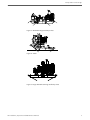
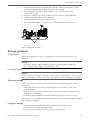
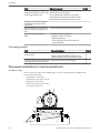
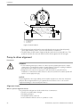
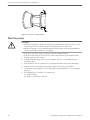
Figure 18: Example of incorrect parallel alignment
5. Repeat the previous steps until the permitted reading value is achieved.
NOTICE:
Use the specified permitted reading values unless specified otherwise by the coupling
manufacturer. Failure to do so may result in reducing the reliability of the pump.
Perform parallel alignment for a vertical correction
Before you start this procedure, make sure that the dial indicators are properly attached
for measurement.
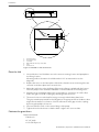
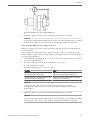
A unit is in parallel alignment when the parallel indicator (P) does not vary by more than
the values given on the included coupling drawing as measured at four points 90° apart at
the operating temperature.
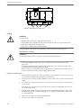
1. Set the parallel alignment indicator (P) to zero at the top-center position (12 o’clock) of
the driver coupling half (Y).
2. Rotate the indicator to the bottom-center position (6 o’clock).
3. Record the indicator reading.
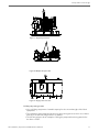
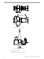
Example illustration given in previous section.
Condition
Action
Negative reading value: The pump coupling half (X) is Remove shims of a thickness equal to half of the
lower than the driver coupling half (Y).
indicator reading value under each driver foot.
Positive reading value: The pump coupling half (X) is Add shims of a thickness equal to half of the indicator
higher than the driver coupling half (Y).
reading value to each driver foot.
NOTICE:
You must use an equal amount of shims with each driver foot to prevent
misalignment. Failure to do so can result in equipment damage or decreased
performance.
4. Repeat the previous steps until the permitted reading value is achieved.
NOTICE:
Use the specified permitted reading values unless specified otherwise by the coupling
manufacturer. Failure to do so may result in reducing the reliability of the pump.
HL Installation, Operation and Maintenance Manual
29