Download OPERATING INSTRUCTIONS GB

Transcript
PRONAR Sp. z o.o.
17-210 NAREW, UL. MICKIEWICZA 101A, PODLASKIE PROVINCE
tel.:
fax:
+48 085 681 63 29
+48 085 681 63 81
+48 085 681 63 83
+48 085 681 64 29
+48 085 681 63 82
+48 085 682 71 10
www.pronar.pl
OPERATING INSTRUCTIONS
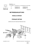
ROTARY WINDROWER RAKES
PRONAR ZKP300
TRANSLATION OF THE ORIGINAL INSTRUCTIONS
ISSUE 2A-01-2010
PUBLICATION NO 178N-00000000-UM
GB
ROTARY WINDROWER RAKES
PRONAR ZKP300
MACHINE IDENTIFICATION
SYMBOL /TYPE:
SERIAL NUMBER:
ZKP300
INTRODUCTION
Information contained herein is current at date of publication. As a result of improvements,
some numerical values and illustrations contained in this publication may not correspond to
the factual specification of the machine supplied to the user. The manufacturer reserves the
right to introduce design changes in machines produced that facilitate operation and improve
the quality of their work, without making minor amendments to these operating instructions.
Please send comments and observations on the subject of the design and operation of the
machine to the manufacturer. This information enables objective evaluation of the machines
produced and provides indications for their further modernisation. Information on significant
design changes are passed on to users with the aid of the information insert attached to
these operating instructions (annexes).
The operating instructions are an integral part of the machine's documentation. Before using
the tractor, the user must familiarise himself with the content of these instructions and
observe all recommendations. This guarantees safe operation and ensures malfunction free
work of the machine. The machine is designed to meet obligatory standards, documents and
legal regulations currently in force.
The instructions describe the basic principles of safe use and operation of PRONAR ZKP300
rotary windrower rakes. If the information contained in the operating instructions needs
clarification then the user should refer for assistance to the sale point where the machine was
purchased or to the manufacturer.
Manufacturer's address:
PRONAR Sp. z o.o.
ul. Mickiewicza 101A
17-210 Narew
Contact telephones
+48 085 681 63 29
+48 085 681 64 29
+48 085 681 63 81
+48 085 681 63 82
Information, descriptions of danger and precautions and also recommendations and orders
associated with user safety instructions are marked:
and also preceded by the word "DANGER”. Failure to observe the instructions may
endanger the machine operator's or other person's health or life.
Particularly important information and instructions, the observance of which is essential, are
distinguished in the text by the sign:
and also preceded either word "ATTENTION". Failure to observe the instructions may lead
to damage to the machine as a result of improper operation, regulation or use.
In order to focus the user's attention on the need to perform technical maintenance, the
relevant section of the operating instructions is marked with the pictogram:
TABLE OF CONTENTS
1
BASIC INFORMATION
1.1
1.1
IDENTIFICATION
1.2
1.2
INTENDED USE
1.3
1.3
FITTINGS
1.4
1.4
WARRANTY CONDITIONS
1.4
1.5
TRANSPORT
1.6
1.6
ENVIRONMENTAL HAZARDS
1.8
1.7
WITHDRAWAL FROM USE
1.8
2
SAFETY IN USE
2.1
2.1
BASIC SAFETY PRINCIPLES
2.2
2.2
PRINCIPLES WHEN TRAVELLING ON PUBLIC ROADS
2.6
2.3
DESCRIPTION OF MINIMAL RISK
2.6
2.4
INFORMATION AND WARNING STICKERS
2.7
3
CONSTRUCTION AND PRINCIPLE OF OPERATION
3.1
3.1
TECHNICAL SPECIFICATION
3.2
3.2
ROTARY WINDROWER RAKES DESIGN
3.2
3.3
HITCHING SYSTEM
3.4
3.4
OPERATING PRINCIPLE
3.6
4
CORRECT USE
4.1
4.1
PREPARING FOR WORK BEFORE FIRST USE
4.2
4.2
TECHNICAL INSPECTION OF WINDROWER
4.4
4.3
ATTACHING TO TRACTOR
4.5
4.4
PREPARATION OF WINDROWER FOR WORK
4.6
4.4.1
MOUNTING OF RAKING ARMS
4.7
4.4.2
SETTING GUARDS
4.8
4.4.3
SETTING WORKING HEIGHT
4.9
4.5
CONNECTING DRIVESHAFT
4.11
4.6
RAKING
4.13
4.7
DISCONNECTING THE WINDROWER
4.14
4.8
PREPARATION OF WINDROWER FOR TRANSPORT
4.14
5
TECHNICAL MAINTENANCE
5.1
5.1
PRINCIPLES OF SAFE TRACTOR OPERATION
5.2
5.2
REDUCTION GEAR OPERATION
5.2
5.3
STORAGE
5.4
5.4
LUBRICATION
5.5
5.5
INSPECTION AND CHANGING RAKING FINGERS
5.7
5.6
TIGHTENING TORQUE FOR NUT AND BOLT CONNECTIONS
5.9
SECTION
1
BASIC INFORMATION
IDENTIFICATION
INTENDED USE
FITTINGS
WARRANTY CONDITIONS
TRANSPORT
ENVIRONMENTAL HAZARDS
WITHDRAWAL FROM USE
1.1
1.1 IDENTIFICATION
FIGURE 1.1A
Location of the data plate
(1) data plate
The ZKP 300 rotary windrower is marked with a data plate (1), placed on left side of
machine's lifting arm. When buying the rotary windrower check that the serial numbers on the
machine agree with the number written in the WARRANTY BOOK, in the sales documents
and in the OPERATING INSTRUCTIONS.
The meaning of the individual fields found on the data plate are presented in the table below:
A - machine name,
B - serial number,
C - machine type/symbol
D - year of manufacture,
E - gross weight
1.2
F - Quality control stamp,
G - machine name, name extension.
1.2 INTENDED USE
Rotary windrower rakes are designed for agricultural work: raking cut swaths (straw, grass,
hays) and gathering it into windrows on stone free grassland with a level surface. Do NOT
use the machine for any other purpose. Using it as intended also involves all actions
connected with the safe and proper operation and maintenance of the machine. Due to the
above, the user is obliged to:
•
familiarise himself with the content of this publication and the content of the
telescopic articulated shaft operating instructions and adhere to the
recommendations contained in these documents,
•
understand the operating principle of the machine's operation and of its safe
and proper use,
•
comply with general safety regulations while working,
•
prevent accidents,
•
comply with road traffic regulations.
TABLE 1.1
THE AGRICULTURAL TRACTOR'S REQUIREMENTS
CONTENTS
MEASURED
AS
REQUIREMENTS
-
I or II
RPM
540
-
1 3/8’’ / 6
kW /
Horsepower
14.7 / 20
Resr three-point linkage
Category
Power take-off shaft
Rotation speed
Type / number of PTO splines
Other requirements
Minimum power demand
1.3
Do NOT perform unauthorised repairs and modifications to the windrower as this shall be
treated by the Manufacturer as misusing the machine.
The machine may only be used by appropriately trained users, who are aware of the
dangers, construction and operating principles of the windrower. Repairs to the machine shall
only be made by qualified personnel (in the guarantee period all repairs must be performed in
the guarantee service, indicated by the Manufacturer). Maintenance and repairs that can be
performed by the user, are described in section 5.
IMPORTANT!
The windrower must not be used for purposes other than those for which it is intended.
1.3 FITTINGS
FITTINGS
OPERATING INSTRUCTIONS
•
WARRANTY BOOK
•
Articulated, telescopic shaft (complete)
•
OPTION
ZKP 300 ROTARY WINDROWER RAKES FITTINGS
STANDARD
TABLE 1.2
Recommended articulated telescopic shafts:
•
7102086CE007128 B&P,
•
1620-6200-086-02 Weasler,
•
T200860EN112U24 Comer.
1.4 WARRANTY CONDITIONS
PRONAR Sp. z o.o., Narew guarantees the reliable operation of the machine when it is used
according to its intended purpose as described in the OPERATOR'S MANUAL.
1.4
The repair period is specified in the WARRANTY BOOK.
The guarantee does not cover those parts and sub-assemblies of the machine which are
subject to wear in normal usage conditions, regardless of the warranty period. Consumables
include the following parts/sub-assemblies:
•
tyres,
•
spring tine fingers,
•
bearings.
The warranty service only applies to such cases as: mechanical damage which is not the
user's fault, factory defects of parts, etc.
In the event of damage arising from:
•
mechanical damage which is the user's fault, caused by road accidents,
•
by inappropriate use, regulation or maintenance, use of the windrower for
purposes other than those for which it is intended,
•
use of a damaged windrower,
•
repairs carried out by unauthorised persons, improperly carried out repairs,
•
arbitrary and wilful adjustments to the windrower's structure,
the user will lose the right to warranty service.
The user is obliged to report immediately on noticing any wear in the paint coating or traces
of corrosion, and to have the faults rectified whether they are covered by the guarantee or
not. Detailed guarantee regulations are contained in the WARRANTY BOOK attached to
each machine.
ATTENTION!
Demand that the seller carefully and precisely fills out the WARRANTY BOOK and
guarantee repair coupons. A missing date of purchase or sale point stamp, may make
the user ineligible for any warranty repair or refund.
1.5
1.5 TRANSPORT
The windrower is prepared for sale in a completely assembled condition and does not require
packing. Packing consists solely of the machine's technical documentation and operating
instructions.
ATTENTION!
When transporting independently, the user must familiarise himself with the content of
these instructions and observe their recommendations. When being transported on a
motor vehicle the windrower must be mounted on the vehicle's platform in accordance
with the transport safety requirements. The driver of the vehicle should take particular
care while driving.
Supply to user takes place by transport vehicle. Transport of the windrower is permissible
connected to a tractor provided the tractor's driver familiarises himself with the machine's
operating instructions and particularly with information concerning safety and principles of
connection and transport of windrower on public roads. Do NOT drive the tractor with
windrower connected when visibility is limited.
When loading and unloading the windrower, comply with the general principles of workplace
health and safety for reloading work. Persons operating reloading equipment must have the
qualifications required to operate these machines.
The windrower should be attached to lifting equipment in places shown on figure (1.2A), i.e.
to transport lug (1) and central connection pin (2), which are located to the front and rear of
lifting arm. Securing point is marked with information sticker. It is recommended that during
transport of the machine the extending arm together with forming shield are dismantled. In
the event that cable or strap of transloading equipment may be caught by protruding rake
elements placed in transport position, it is necessary to dismantle them. When raising the
windrower take particular care due to the possibility of tipping over the machine and the risk
of injuries from protruding machine parts.
1.6
FIGURE 1.2A
Points of windrower suspension
(1) transport lug, (2) central connection pin
DANGER
During loading, windrower should be placed in transport position. Extending arm and the
forming shield should be dismantled.
The windrower should be attached firmly to the platform of the vehicle using straps or chains
fitted with a tightening mechanism. The fastening equipment used must have a valid safety
certificate. Wedges or other objects without sharp edges should be placed under the wheels
1.7
of the windrower to prevent it from rolling. The wedges must be fixed to the platform of the
vehicle. During reloading work, particular care should be taken not to damage parts of the
windrower's fittings or the paint coat.
1.6 ENVIRONMENTAL HAZARDS
A hydraulic oil leak from the reducer constitutes a direct threat to the natural environment
owing to its limited biodegradability. While carrying out maintenance and repair work which
involves the risk of an oil leak, this work should take place on an oil resistant floor or surface.
In the event of oil leaking into the environment, first of all safeguard the source of the leak,
and then remove the leaked oil using available means. Remaining oil should be removed
using sorbents, or by mixing the oil with sand, sawdust or other absorbent materials. The oil
pollution, once gathered up, should be kept in a sealed, marked, hydrocarbon resistant
container, and then passed on to the appropriate oil waste recycling centre. The container
should be kept away from heat sources, flammable materials and food.
Oil which has been used up or is unsuitable for further use owing to a loss of its properties
should be stored in its original packaging in the conditions described above.
1.7 WITHDRAWAL FROM USE
Should the user decide to withdraw the machine from use, the entire windrower should be
taken to a scrap yard. When spare parts are changed, worn out or damaged parts should be
taken to a collection point for recyclable raw materials. Hydraulic oil should be taken to the
appropriate facility dealing with the re-use of this type of waste.
1.8
SECTION
2
SAFETY IN USE
BASIC SAFETY PRINCIPLES
PRINCIPLES WHEN TRAVELLING ON PUBLIC ROADS
DESCRIPTION OF MINIMAL RISK
INFORMATION AND WARNING STICKERS
2.1
2.1 BASIC SAFETY PRINCIPLES
•
Before using the windrower the user should thoroughly acquaint himself with the
content of these instructions and the articulated telescopic shaft instructions and
adhere to the recommendations contained in these documents.
•
The windrower may only be used and operated by persons qualified to drive
agricultural tractors and trained in the use of the machine.
•
If the information contained in the operating instructions is difficult to
understand, contact a seller who runs an authorised technical service on behalf
of the manufacturer, or contact the manufacturer directly.
•
Careless and improper use and operation of the windrower, and non-adherence
to the recommendations included in these instructions are dangerous for the
health.
•
Be warned that a minimal risk does exist, and for this reason the fundamental
basis for using this machine should be the application of safety principles and
sensible behaviour.
•
The windrower must never be used by persons who are not authorised to drive
agricultural tractors, including children and people under the influence of alcohol
or other drugs.
•
Non-adherence to the principles of safe use creates a danger for the health and
life of the operator and others.
•
The windrower must not be used for purposes other than those for which it is
intended. Anyone who uses the machine other than the way intended takes full
responsibility on himself for any consequences of this use.
•
Any modification to the windrower frees PRONAR Narew from any responsibility
for damage or detriment to health which may arise as a result.
•
Before using the windrower always check its technical condition. In particular
check the technical condition of the hitching system, drive system, mounting of
rakes and protective guards.
2.2
•
Windrower disconnected from tractor must be supported with the aid of
supports and secured against rolling away by using wheel wedges or other
elements without sharp edges.
•
Do NOT ride on the windrower or transport any materials on it.
•
The windrower may only be used when all the safety guards and other
protective elements are technically sound and correctly positioned. In the event
of loss or destruction of the safety guards, they must be replaced with new
ones.
•
The machine must not be used when not in working order.
•
While reversing and during turns, the windrower drive must be disengaged.
•
Do NOT leave the tractor cab, when the machine drive is engaged.
•
Do NOT stand within the windrower's working zone.
•
Before hitching the machine to the tractor, check the technical condition of the
hitching system of the windrower and the tractor.
•
Be especially careful when attaching the machine.
•
When reversing the tractor, there must be nobody between the windrower and
the tractor.
•
To attach the machine to the tractor only the rear Three-Point Linkage System
may be used. After linking the machine, check the safeguards.
•
Use an articulated telescopic shaft recommended by the Manufacturer.
•
The windrower may not be used or transported in conditions of limited visibility.
•
The articulated telescopic shaft has markings on the casing, indicating which
end of the shaft shall be connected to the tractor.
•
Never use a damaged articulated telescopic shaft, it may cause an accident. A
damaged shaft must be repaired or replaced.
•
Disconnect the drive shaft each time when it is not necessary to drive the
machine, or when the tractor and windrower are at an unsuitable angle to each
other.
2.3
•
The chains preventing the shaft cover from turning while the shaft is working,
shall be secured to a fixed element of windrower structure.
•
Do NOT use the securing chains to support the shaft while machine is parked or
when transporting the windrower.
•
Before using the windrower the user should thoroughly acquaint himself with the
articulating telescopic shaft instructions and adhere to the recommendations
contained in them.
•
The windrower may only be connected to the tractor with the aid of the
appropriately selected articulated telescopic shaft recommended by the
Manufacturer.
•
The driveshaft must be equipped with a cover. Do NOT use the shaft with
damaged or missing guards.
•
After connecting shaft ensure that it is correctly and safely connected to the
tractor and to the windrower.
•
Before starting the windrower make sure that there are no bystanders
(especially children) or animals in the danger zone. The machine operator is
obliged to ensure proper visibility of the machine and the working area.
•
While windrowing apply working speed recommendations.
•
When using the windrower and power takeoff shaft, do not use PTO rotation
speed greater than 540 revs/min. Do NOT overload shaft and windrower and
also engage the clutch suddenly. Before starting articulated telescopic shaft
make certain that the PTO shaft rotation direction is correct.
•
During windrowing use the correct working position.
•
Before disconnecting the shaft, turn off the tractor engine and remove the key
from the ignition.
•
When working on the tyres, wedges or other objects without sharp edges
should be placed under the wheels of the windrower to prevent it from rolling.
•
Repair work on the wheels or tyres should be carried out by persons trained
and entitled to do so. This work should be carried out using appropriately
selected tools.
2.4
•
In order to reduce the danger of fire the machine must be kept in a clean
condition.
•
In the event of work requiring the windrower to be raised, use properly certified
hydraulic or mechanical lifts for this purpose. After lifting the windrower, stable
and durable supports must also be used. Work must not be carried out under a
machine which has only been raised with a lift.
•
The windrower must not be supported using fragile elements (bricks or concrete
blocks).
•
Check the tyre pressure regularly.
•
In the event of any fault or damage whatsoever, disconnect the windrower from
use until the fault has been fixed. The machine must not be used when not in
working order.
•
When operating the machine wear protective gloves and use the appropriate
tools.
•
Servicing and repair work should be carried out in line with the general
principles of workplace health and safety. In the event of injury, the wound must
be immediately cleaned and disinfected. In the event of more serious injuries,
seek a doctor's advice.
•
Repair, maintenance and cleaning work should be carried out with the tractor's
engine switched off and the ignition key removed.
•
Regularly check the condition of the screw and nut connections.
•
The paint coating should be cleaned off before beginning welding work. Burning
paint fumes are poisonous for people and animals. Welding work should be
carried out in a well lit and well ventilated space.
•
During welding work pay attention to flammable or fusible elements. If there is a
risk that they will catch fire or be damaged, they should be removed or covered
with non-flammable material before commencing welding work. The windrower
must be disconnected from the tractor before commencing electric welding.
•
During the warranty period, any repairs may only be carried out by a Warranty
Service authorised by the manufacturer.
2.5
•
Should it be necessary to change individual parts, use only those parts
indicated by the manufacturer. Non-adherence to these requirements may
cause danger to the health and the user's and other people's lives, and also
damage the machine.
•
After completing work connected with greasing, remove excess oil or grease.
•
Do NOT wear loose clothing, straps or whatever may become wrapped round
the rotating drive shaft. Contact with rotating articulated telescopic shaft may
cause severe injuries.
•
Do NOT go over and under the shaft or to stand on it equally during work as
also when the machine is parked.
2.2 PRINCIPLES WHEN TRAVELLING ON PUBLIC ROADS
•
When travelling on public roads, respect the road traffic regulations.
•
Do not exceed the maximum speed when travelling. Adjust your speed to the
road conditions.
•
Before beginning travel, the windrower must be placed in transport position and
raised using the rear three-point linkage system. While parking the windrower
should be lowered.
•
It is forbidden for the tractor driver to leave his position while the tractor is
moving.
2.3 DESCRIPTION OF MINIMAL RISK
Pronar Sp. z o. o. in Narew has made every effort to eliminate the risk of accidents. There is,
however, a certain minimal risk which could lead to an accident, and this is connected mainly
with the actions described below:
•
using the windrower for purposes other than those for which it is intended,
•
being between the tractor and the windrower while the engine is running and
when the machine is being attached,
•
being on the machine while the engine is running,
•
operating the windrower with the safety guards removed or faulty,
2.6
•
not keeping a safe distance from the danger zone or being within the zones
while the windrower is operating,
•
operation of the windrower by persons under the influence of alcohol,
•
cleaning, maintenance and technical checks of the windrower.
•
using unreliable articulated telescopic shaft.
The minimal risk may be kept to a minimum by following the recommendations below:
•
prudent and unhurried operation of the machine,
•
sensible application of the remarks and recommendations contained in the
operating instructions,
•
keeping a safe distance from forbidden or dangerous places,
•
a ban on being on the machine when it is operating,
•
carrying out repair and maintenance work in line with operating safety
principles,
•
carrying out repair and maintenance work by persons trained to do so,
•
using strictly suited protective clothing,
•
ensuring unauthorised persons have no access to the machine, especially
children.
2.4 INFORMATION AND WARNING STICKERS
The windrower is labelled with the information and warning stickers mentioned in table (2.1).
The symbols are positioned as presented in figure (2.1A). Throughout the time it is in use, the
user of the machine is obliged to take care that notices and warning and information symbols
located on the windrower are clear and legible. In the event of their destruction, they must be
replaced with new ones. Stickers with notices and symbols are available from the
manufacturer, or from the retailer where the windrower was purchased. New assemblies,
changed during repair, must be labelled once again with the appropriate safety signs.
2.7
TABLE 2.1 INFORMATION AND WARNING STICKERS
ITEM
SAFETY SYMBOL
DESCRIPTION
1
Before starting work, familiarise
yourself with the contents of the
OPERATING INSTRUCTIONS.
2
Before beginning servicing or
repairs, switch off engine and
remove key from ignition
3
Danger associated with the
rotating articulated telescopic
shaft.
4
Maximum allowable PTO shaft
rotation speed is 540 revs/min.
2.8
ITEM
SAFETY SYMBOL
DESCRIPTION
5
Danger of crushing or severing of
limbs. Be careful while folding and
unfolding side guards.
6
Thrown out objects, danger to the
whole body. Keep a safe distance
from machine during work of
windrower.
7
Danger of being struck by rotating
elements of the machine. Keep a
safe distance from raking
assembly.
8
Windrower type
9
Transport catch point marking.
2.9
FIGURE 2.1A
Locations of information and warning stickers.
Labelling in line with table 2.1 „Information and warning stickers”.
2.10
SECTION
3
CONSTRUCTION AND
PRINCIPLE OF
OPERATION
TECHNICAL SPECIFICATION
ROTARY WINDROWER RAKES DESIGN
HITCHING SYSTEM
OPERATING PRINCIPLE
3.1
3.1 TECHNICAL SPECIFICATION
TABLE 3.1
ROTARY WINDROWER RAKES TECHNICAL DATA
CONTENTS
UNIT
ZKP 300
Total length in working setting
mm
3 030
Total length in transport setting
mm
2,190
minimum
mm
3,135
maximum
mm
3,635
Width in transport setting
mm
1,110
Height in working setting
mm
1,120
Height in transport setting
mm
1 855
Raking width
mm
3 000
Minimum tractor power demand
KM
18
RPM
540
Tare weight
kg
290
Work output
ha/h
3
Recommended working speed
km/h
10
dB
below 75
-
15x6.0-6
kPa
200
Dimensions
Width in working setting
Technical specification
Maximum PTO speed
Noise emission level
Tyres
Tyre
Air pressure in the tyres
3.2 ROTARY WINDROWER RAKES DESIGN
Construction of the rake carousel is shown in figure (3.1A). The machine's main subassembly is the support frame (1). In the front part is the system for mounting the machine to
the Three-Point Linkage of the tractor, category I or II. In the rear part of the windrower is the
transmission gearing system (2) of the working assembly. The reducer is powered by the
articulated telescopic shaft and then through the driveshaft placed in the extension (4) of the
support frame (1).
3.2
FIGURE 3.1A
Rotary windrower rakes design
(1) frame, (2) reducer, (3) raking arm, (4) extender, (5) springtine finger, (6) securing angle,
(7) linchpin, (8) wheel beam, (9) undercarriage leg, (10) wheel, (11) extension arm,
(12) shield, (13), (14) shield wing struts, (15) support, (16) regulation screw, (17) screw lock
3.3
The transmission gearing (2) has 8 radiating shafts, to which are secured raking arms (3).
Each of the arms is equipped with 3 springtine fingers for raking the swath. They are
mounted on the arm extension with the aid of securing angles (6), which prevent fingers from
sliding or rotating. Arms are secured to the gearing transmission with the aid of linchpins (7).
Rake suspension is connected in the lower part of the transmission gearing. The
undercarriage legs (9) together with the wheels (10) are secured to the wheel beams (8). The
extension arm (11) together with the forming shield (12) secured to it is on the left side of the
windrower. During machine work the shield constitutes a barrier for the raked swath, due to
which it is not scattered but formed into a regular windrow. The extension arm is secured by
the left shield wing strut (13) and locked with a linchpin. The height of raking arm setting
above the surface is regulated by the regulation screw (16) and secured by the interlock (17).
3.3 HITCHING SYSTEM
The windrower rake carousel is mounted on the tractor using the hitching system integrated
in the support frame of the machine. Figure (3.2A), shows detailed mounting structure.
The windrower is adapted to agricultural tractors equipped with three-point linkage of
category I or II. Pins (1) and (2) – external - serve to attach the machine to a tractor equipped
with category II three-point linkage, similarly pins (3) and (4) – internal - for linkage to factor
tractor equipped with category I three-point linkage. The upper pin it is common to both
categories, designed for securing the upper suspension point irrespective of three-point
linkage category. The upper pin may be placed in one of two available sockets. The upper
socket (A) with an elongated shape, it is used during machine work (working position), socket
(B) for transporting the windrower.
3.4
FIGURE 3.2A
Hitching system
(1), (2) lower securing pins (three-point linkage – II category), (3), (4) lower securing pins
(three-point linkage – I category), (5) upper securing pin, (6), (7) locking linchpins,
(A) working pin position socket, (B) travelling pin position socket
3.5
3.4 OPERATING PRINCIPLE
The rotary windrower rakes is equipped with the reduction gearing driven by the tractor PTO.
The torque is transferred through transfer shafts. The reducer's design ensures the rotation
movement of the raking assembly in an anticlockwise direction.
The gear's cam mechanism enables the rotation of individual arms, due to which the
springtine fingers are lowered or raised according to current setting. During raking – figure
(3.3A), area (A) - springtine fingers are lowered almost vertically. The raked swath is retained
by the forming shield, due to which it is formed into an even windrow. In remaining instances
the raking springtines are raised to the upper position.
FIGURE 3.3A
The windrower's operating principle
(A) swath raking phase
3.6
SECTION
4
CORRECT USE
PREPARING FOR WORK BEFORE FIRST USE
TECHNICAL INSPECTION OF WINDROWER
ATTACHING TO TRACTOR
PREPARATION OF WINDROWER FOR WORK
CONNECTING DRIVESHAFT
RAKING
DISCONNECTING THE WINDROWER
PREPARATION OF WINDROWER FOR TRANSPORT
4.1
4.1 PREPARING FOR WORK BEFORE FIRST USE
The manufacturer guarantees that the windrower is fully operational and has been checked
according to quality control procedures and is ready for normal use. This does not release
the user from an obligation to check the machine's condition after delivery and before first
use. The machine is delivered to the user in a completely assembled state.
Before connecting to tractor, machine operator must inspect the technical condition of the
windrower and prepare it for test startup. In order to do this:
•
the user must familiarise himself with the content of these instructions and
observe all recommendations, understand the design and the principle of
machine operation
•
check the condition of protective paint coat,
•
Inspect windrower's individual components for mechanical damage resulting
from incorrect transport (dents, piercing, deflections or broken components),
•
Check the windrower's all lubrication points, lubricate the machine as needed
according to recommendations provided in section 5,
•
Check technical condition of tyres and tyre pressure,
•
check if wheel and rocker mounting is correct,
•
check if springtine finger and guard mounting is correct,
•
check technical condition of hitching system pins and locking linchpins,
•
check lubricating oil level in reduction gear.
If all the above checks have been performed and there is no doubt as to the windrower's
good technical condition, it can be connected to tractor. Start the tractors engine, check all
systems and test the windrower before beginning work. In order to inspect:
•
Hitch windrower to tractor.
•
set raking arms, raise windrower upwards maximally using the crank, so that
raking fingers do not touch surface,
•
connect articulated telescopic shaft to tractor and windrower
•
start PTO drive.
4.2
Engage rake drive for several minutes, and check the following:
•
there is no knocking or noise in the drive system arising from scraping or
grinding of metal elements,
•
proper rotation of raking system,
•
proper action of cam mechanism (raking fingers should be lowered and raised
according to current arm position).
ATTENTION!
Before using the windrower always check its technical condition. In particular check the
technical condition of the raking system, wheel system, all protective guards and correct
condition of mounting of raking fingers.
The windrower's operation at no load should be smooth. Shaking of raking mechanism and
whole machine is not acceptable, nor is changed noise and vibrations coming from loose nut
and bolt connections. After stopping windrower check fastening of rake fingers and raking
arms. Check that the gear oil does not leak from the reduction gearing.
DANGER
Before using the windrower, the user must thoroughly familiarise himself with the
content of these instructions.
Careless and improper use and operation of the windrower, and non-adherence to the
recommendations included in these instructions are dangerous for the health.
The windrower must never be used by persons who are not authorised to drive
agricultural tractors, including children and people under the influence of alcohol or
other drugs.
Non-adherence to the principles of safe use creates a danger for the health and life of the
operator and others.
DANGER
Before starting the windrower, make sure that there are no bystanders in the danger
zone.
4.3
If any faults are detected they must be identified and rectified. If a fault cannot be rectified or
the repair could void the guarantee, please contact retailer for additional clarifications.
4.2 TECHNICAL INSPECTION OF WINDROWER
When preparing the windrower for normal use, check individual elements according to
guidelines presented in table (4.1).
TABLE 4.1 TECHNICAL INSPECTION SCHEDULE
Check mounting of rake fingers to
raking arms
Ensure that fingers are correctly
tightened.
Check technical condition of tyres
and tyre pressure,
Visually inspect the tyres and if they
are properly inflated.
Check technical condition of tyres
and tyre pressure,
Check the condition of tyre tread,
lateral surfaces, wheel rim and if
necessary inflate the tyres up to
recommend pressure
Check of all main nut and bolt
connections are properly tightened
Torque values should be according to
table (5.2)
Lubrication
Lubricate elements according to
guidelines presented in section
"lubrication points".
ATTENTION!
The windrower must not be used when not in working order.
4.4
Before each use
check the technical condition of
safeguards, if complete and correctly
mounted.
Every
month
Condition of safeguards
FREQUENCY
After the
winter
SERVICE OPERATION
Accordi
ng to
table
(5.1)
DESCRIPTION
4.3 ATTACHING TO TRACTOR
FIGURE 4.1A
Attaching windrower to tractor
(1), (2) lower three-point linkage securing pins, (3) upper securing pins, (4) support,
(5) locking linchpin, (A), (B) lower three-point linkage hitching points, (C) upper three-point
linkage connection
The windrower may only be connected to tractors with power output greater than 20 hp,
equipped with category I or II rear three-point linkage.
•
Drive tractor to windrower.
•
Reverse tractor ensuring that there is nobody between the tractor and the
windrower.
4.5
•
Reversing the tractor bring the lower three-point linkage connection points (A)
and (B) close to pins (1) and (2) of windrower.
•
Set connection arms (A) and (B) of tractor at appropriate height.
•
Switch off tractor's engine and prevent it from rolling.
•
Connect lower pins (1) and (2) with connecting arms (A) and (B) and lock with
the aid of linchpins.
•
Release top link of tractor and connect it with pin (3) of windrower and lock with
linchpin.
•
Raise support (4) and secure with linchpin.
ATTENTION!
Before using the windrower, the user must thoroughly familiarise himself with the
tractor's operating instructions.
The lower connection arms must at identical height. If not the windrower shall be tilted to
the left or right side, which will interfere with the machine's operation. Appropriate
regulation is made with the aid of the tractor lower three-point linkage suspender rods.
DANGER
Exercise caution when linking the machine.
The top link pin must be in the upper socket of the hitching system, if the windrower is
prepared for field work – in working position. To transport the windrower use the lower socket
– transport position – compare with figure (3.2A).
4.4 PREPARATION OF WINDROWER FOR WORK
Windrower transported to the field must be set in appropriate working position. Preparing of
the machine for work must only take place exclusively where the windrower shall work.
Travel of machine on roads with raking arms installed and extended guards is forbidden.
4.6
4.4.1 MOUNTING OF RAKING ARMS
FIGURE 4.2A
mounting of raking arms
(1) locking linchpin, (2) raking arm, (3) securing of arm
•
Stop tractor and remove the key from the ignition, ensure that unauthorised persons
do not have access to the tractor.
•
immobilise tractor with parking brake,
•
Remove securing linchpin (1) from left and right side of windrower, take out arm (2).
•
Insert arms to attachment point (3) and secure with linchpins (1).
4.7
ATTENTION!
Raking arms in transport position secured with the aid of 2 linchpins (1 linchpin for each
side). These linchpins are used to secure raking arms in working position.
DANGER
Do NOT operate the machine when the complete set of 8 raking arms is not installed.
Raking arms shall be mounted with tractor engine switched off. Remove the key from the
ignition, ensure that unauthorised persons do not have access to the tractor. Tractor
shall be immobilised with parking brake.
4.4.2 SETTING GUARDS
•
Holding guard frame (3) in upper setting, remove locking linchpin (2) from right
side of machine.
•
Set right guard in working position, insert linchpin in its place.
•
Holding left guard frame (1) in upper setting, remove locking linchpin (2) from
left side of machine.
•
Set left guard in working position, insert linchpin in its place.
•
Take out locking linchpin (4), extend arm (5) set forming guard at chosen
working width. Insert securing linchpin.
DANGER
During lowering of guards it is necessary to be particularly careful with regard to the
danger of uncontrolled lowering of these sub-assemblies.
DANGER
Tractor engine should be switched off during lowering of guards. Remove the key from
the ignition, ensure that unauthorised persons do not have access to the tractor. Tractor
shall be immobilised with parking brake.
4.8
The forming guard is the barrier for the raked swath. Thanks to the swath is formed into an
even windrow of the required width. When setting the guard observe the principle that the
greater the swath then the wider the working width, and the other way round, the lower the
quantity of swath then the barrier distance should be less.
FIGURE 4.3A
Setting side guards
(1) left guard arm, (2) locking linchpin, (3) right guard arm, (4) linchpin securing extended
arm, (5) extended arm
4.4.3 SETTING WORKING HEIGHT
The correct working position of windrower has a decisive influence on the cleanness of the
raked swath, quality of windrow forming and working comfort.
One of the basic factors deciding the correctness of machine setting is the correct height
regulation of the lower three-point linkage tractor lift arms. Their height is regulated by the
suspender rods. Both the lift arms must be at the same height, if not the windrower may be
tilted to the left or the right side. This must be done before connecting windrower to the
tractor.
4.9
ATTENTION!
Read the instructions on regulation of the three-point linkage which are part of the
tractor's operating instructions.
FIGURE 4.4A
Setting working height
(1) crank, (2) counter nut, (3) reduction gearing
Regulation of working position is performed after lowering the machine to the ground.
Working position of windrower is regulated by performing the following actions:
•
park tractor and windrower on flat level ground,
•
set top link pin in sliding socket,
•
set rear three point linkage in position regulation mode,
•
set height of tractor lower three-point linkage forks,
•
set length of top link,
•
unscrew counter nut (2) anticlockwise - figure (4.4A),
4.10
•
Regulate height of windrower using the crank in such a way that the rake
assembly is in a horizontal plane – parallel to the ground surface and the
springtine fingers lightly touch the ground, the top link pin should be in the
middle of the sliding socket,
•
Tighten counter nut and check machine setting.
Height of rakes shall be set in such a way that springtine fingers of raking assembly delicately
touch the ground while working. Windrower's support frame should be set horizontally,
parallel to the ground Height selection also depends on the amount of cut swath, degree of
dampness, raking speed and also the ground over which the windrower is moving. If the
height is too high there is a risk that not all of the swath will be raked. At a low setting the
swath may be contaminated with disturbed earth, turf and stones etc. Furthermore there is
increased danger of damage to the windrower, mainly for raking fingers and their mounting to
the arms. Height selection should be checked frequently during working and if necessary the
setting should be corrected.
DANGER
Regulation of windrower's working height must be done with the tractor engine switched
off. Remove the key from the ignition, ensure that unauthorised persons do not have
access to the tractor. Tractor shall be immobilised with parking brake.
4.5 CONNECTING DRIVESHAFT
The windrower is equipped with the appropriately selected articulated telescopic shaft with
overload protection clutch. Before connecting the windrower it is absolutely necessary to
acquaint oneself with the content of the instructions attached by the manufacturer of the shaft
and observe the instructions contained in them. Before connection to the tractor check the
technical condition of the shaft guard, the completeness and condition of the protecting
chains and the general technical condition of the shaft. Multi splined ends are appropriately
marked, so it is clear which end should be connected to the tractor.
4.11
FIGURE 4.5A
Articulated telescopic shaft with overload protection clutch
(1) articulated telescopic shaft
Shaft is equipped with overload protection clutch, which prevents damage to windrower or
tractor. Torque value for shaft is set in the factory by the manufacturer and may not be
changed by the user. Change of overload protection clutch setting may invalidate the
guarantee
DANGER
The use of articulated telescopic shaft and its technical condition must be in accord with
the operating instructions of articulated telescopic shaft.
4.12
DANGER
Before connecting the shaft, turn off the tractor's engine and remove the key from the
ignition. Ensure that unauthorised persons do not have access to the tractor.
4.6 RAKING
If the windrower is correctly set for working in the field, is totally serviceable and its technical
condition causes no concerns one may commence work. Recommended working speed is 10
km/h or less. At greater travelling speeds the swath may not be properly raked and formed
into windrow. Allowable revolution speed of articulated telescopic shaft is 540 revs/min
however recommended speed is about 450 revs/min. With a very dry swath it is
recommended that PTO shaft speed should be reduced even further.
IMPORTANT!
Do NOT start windrower with PTO revs speed higher than 540 revs/min.
The revolution speed of the shaft and the speed of travel depend on several factors, including
size of swath, degree of moisture, length of swath, type of ground, therefore the selection of
appropriate working parameters rests on the person operating the windrower. During
machine operation the linkage system shall be set in position regulation work mode.
DANGER
Before engaging drive to articulated telescopic shaft make sure that there are no
bystanders, especially children, near the windrower. Maintain proper visibility of
machine during work
Other persons should be at a safe distance from the windrower during work because of
the danger that objects may be thrown (stones, branches from beneath raking fingers.
Raking the swath in order to form it into windrows should be conducted in a system of smaller
areas. During turning or reversing, articulated telescopic shaft should be disengaged and
windrower raised. Width of windrow should be somewhat less that baler intake pickup – if
swath shall be baled.
4.13
4.7 DISCONNECTING THE WINDROWER
In order to disconnect the windrower from the tractor perform the following:
•
lower windrower support and secure with linchpin,
•
lower windrower using three-point linkage to rest position,
•
switch of tractor engine and remove key from ignition,
•
disconnect articulated telescopic shaft,
•
disconnect top link of three-point linkage,
•
disconnect lower windrower pins and drive tractor away.
4.8 PREPARATION OF WINDROWER FOR TRANSPORT
After finishing fieldwork the windrower must be set in transport position. Before beginning
preparation works switch of tractor engine and remove the key from the ignition. Brake tractor
with parking brake and secure tractor cab, ensure that unauthorised persons do not have
access to the tractor.
Travel with rake arms extended in work position is forbidden. During travel they must be
placed in sockets on frame and secured with linchpins.
Side guards shall be raised to vertical position and also secured with linchpins. It is
recommended that forming guard arm is totally retracted.
Disconnection of articulated telescopic shaft is not essential but it is recommended. Turning
sharp corners, especially in field conditions may be hindered because of this. If the shaft is
not taken off, is essential to remember not to engage the PTO drive of the tractor during
transport travel. During transport the windrower must be raised by the three-point linkage.
DANGER
Preparing the windrower for transport may only be done with tractor engine switched off.
Remove the key from the ignition, ensure that unauthorised persons do not have access
to the tractor. Tractor shall be immobilised with parking brake.
Do NOT drive on public roads when visibility is limited.
4.14
SECTION
5
TECHNICAL
MAINTENANCE
PRINCIPLES OF SAFE TRACTOR OPERATION
REDUCTION GEAR OPERATION
STORAGE
LUBRICATION
INSPECTION AND CHANGING RAKING FINGERS
TIGHTENING TORQUE FOR NUT AND BOLT CONNECTIONS
5.1
5.1 PRINCIPLES OF SAFE TRACTOR OPERATION
•
Repair, maintenance and cleaning work should be carried out with the tractor's
engine switched off and the ignition key removed. Ensure that unauthorised
persons, especially children, do not have access to the tractor.
•
The machine must not be used when not in working order.
•
Repair work on the wheels or tyres should be carried out by persons trained
and entitled to do so. This work should be carried out using appropriately
selected tools.
•
In the event of work requiring the windrower to be raised, use properly certified
hydraulic or mechanical lifts for this purpose. After lifting the windrower, stable
and durable supports must also be used. Work must not be carried out under a
machine which has only been raised with a lift.
•
The windrower must not be supported using fragile elements (bricks or concrete
blocks).
•
When operating the machine wear protective gloves and use the appropriate
tools.
•
Servicing and repair work should be carried out in line with the general
principles of workplace health and safety. In the event of injury, the wound must
be immediately cleaned and disinfected. In the event of more serious injuries,
seek a doctor's advice.
5.2 REDUCTION GEAR OPERATION
Service of reduction gear is conducted during general inspection, change or topping up gear
oil. In the event of damage to reducer contact authorised service point in order perform
repairs.
First oil change must be made after the first 50 hours worked. The next oil change should be
made after 500 hours of windrower work or once a year. Most suitable time for changing
reduction gear oil is when preparing for first fieldwork. The quantity of oil necessary to fill the
reduction gear box amounts to 2.8 litres. Reduction gearing oil: SAE90EP.
5.2
FIGURE 5.1A
Changing reduction gear oil
(1) inlet plug
In order to change oil in reducer:
•
set windrower on a hard surface and level the machine
•
unscrew inlet plug (1),
•
unscrew drain plug on lower part of reducer,
•
drain oil into oil resistant tight container, container capacity should be about 4 litres,
•
if oil manufacturer recommends flushing gearing system, that operation should be
performed according to the guidelines of the oil manufacturer (these recommendations
may be detailed on the oil packaging)
•
tighten drain plug,
5.3
•
add oil until oil flows out of inlet opening, tighten plug.
The first oil change should be made after 50 hours of windrower work and the next
change should be after 500 hours or once a year.
During normal operation, lubrication of the entry shaft and the windrower's height regulation
screw is also required – consult section "Lubrication”.
If a leak is noticed, carefully inspect seals and check oil level. Work of reduction gearing with
insufficient oil may cause permanent damage of the mechanism.
Repair of reduction gear during guarantee period may only be performed at specialised
mechanical workshops.
5.3 STORAGE
After completion of work the carousel windrower should be carefully cleaned and washed
with a water jet. While washing do not direct a strong water or steam jet at information and
warning stickers or bearings. Nozzle of pressure or steam washer should be kept at a
distance of not less than 30 cm from cleaned surface.
After cleaning windrower inspect the whole machine, inspect technical condition of individual
elements. Used or damaged elements should be repaired or replaced.
In the event of damage to the paint coat, clean rust and dust from damaged area, degrease
and then paint with undercoat and after it is dry paint with surface coat paint retaining colour
uniformity and even thickness of protective coating. Until the time of repainting the damaged
place may be covered with a thin layer of grease or anticorrosion preparation. Windrower
should be kept in closed or roofed building.
If the windrower will not be used for a long time, it is essential to protect it from adverse
weather, especially rust and accelerated tyre deterioration.
Windrower should be lubricated according to instructions provided. In the event of prolonged
work stoppage, it is essential to lubricate all elements regardless of the period of the last
lubrication process. Additionally before the winter period hitching system pins should be
smeared with grease. The ends of the raking arms and rake mounting sleeves should be
cleaned from any contamination and protected with any widely available anticorrosion agent.
5.4
Tyres should undergo conservation maintenance at least twice a year using the appropriate
preparations designed for this purpose. Complete wheels and tyres should be previously
carefully washed and dried. During longer storage of unused windrower it is recommended
that every 2 to 3 weeks the trailer may be moved a bit so that the place of contact of tyres
with ground is changed. So that tyres are not deformed and maintain proper geometry. Also
tyre pressure should be inspected from time to time, and if necessary pressure should be
increased to appropriate value.
5.4 LUBRICATION
Greasing of windrower shall be performed where indicated on figure (5.2A) as stipulated in
table (5.1). This procedure should be performed using a hand or foot operated grease gun
filled with generally available permanent grease. Before beginning greasing in so far as is
possible remove old grease and other contamination. Remove excess oil or grease
Oil in reduction gearing shall be changed after the first 50 hours, and then after 500 hours or
once a year of use. Detailed description of oil change and service of reduction gear is given
in section 5.1 "Service of reduction gear”
During windrower use the user is obliged to observe greasing instructions according to
attached schedule. Excess greasing substance causes depositing additional
contaminants in places requiring greasing, therefore it is essential to keep individual
machine elements clean.
5.5
FIGURE 5.2A
Windrower greasing points
5.6
TABLE 5.1
GREASING POINTS
ITE
M
NAME
NUMBER
OF
GREASING
POINTS
TYPE OF
GREASE
GREASING
FREQUENCY
1
Undercarriage strut arms
2
PERMANENT
40 hours
2
Shaft bearing
1
PERMANENT
20 hours
3
Multi-splined driveshaft
1
PERMANENT
20 hours
4
Reduction gear bearing
1
PERMANENT
20 hours
5
Gear:
1
OIL
500 hours
6
Regulation screw
2
PERMANENT
60 hours
7
Pin
2
OIL
8 hours
8
Articulated telescopic shaft
IMPORTANT! Marking description in column LP in table (5.1) conforms with numbering shown in figure (5.1A).
 Apply grease to upper threaded part and the lower part of the regulation screw
 Greasing articulated telescopic shaft should be performed according to the instructions of manufacturer.
Detailed information on maintenance is contained in maintenance instructions attached to the shaft.
5.5 INSPECTION AND CHANGING RAKING FINGERS
In order to dismantle raking fingers:
•
unscrew nut (4)
•
dismantle securing angle (2) and screw (3)
•
remove damaged raking finger (1) and mount new finger,
•
place angle and insert screw, tighten nut to appropriate moment.
5.7
Raking fingers and their mounting should be checked while working with windrower.
Damaged elements should be replaced. It is not possible to repair raking fingers.
Each day check condition of raking finger connections to arms and locking linchpins on
raking arms frame in case they have fallen out
FIGURE 5.3A
Changing raking fingers
(1) raking finger, (2) securing angle, (3) screw, (4) self-locking nut
DANGER
Before beginning preparation works switch of tractor engine and remove the key from
the ignition and engage tractor parking brake. Ensure that unauthorised persons do not
have access to the tractor.
5.8
5.6 TIGHTENING TORQUE FOR NUT AND BOLT
CONNECTIONS
Unless other tightening parameters are given, during maintenance repair work apply
appropriate torque to tightening nut and bolt connections. Recommended tightening torque of
most frequently applied nut and bolt connections are given in table (5.2). Given values apply
to non greased steel bolts.
Detailed inspection of tightness of nut and bolt connections should be made after the first 10
hours of work, and then each time at the end of working year of windrower.
FIGURE 5.4A
Bolt with metric thread
(1) bolt strength class, (d) thread diameter
TABLE 5.2
TIGHTENING TORQUE FOR NUT AND BOLT CONNECTIONS
THREAD (d)
5.8
8.8
[mm]
10.9
MD [Nm]
M6
8
10
15
M8
18
25
36
M10
37
49
72
M12
64
85
125
5.9
THREAD (d)
5.8
8.8
[mm]
10.9
MD [Nm]
M14
100
135
200
M16
160
210
310
M20
300
425
610
M24
530
730
1 050
M27
820
1 150
1 650
M30
1 050
1 450
2 100
(MD) – tightening torque, (d) thread diameter
5.10
NOTES
…………………………………………………………………………………………………………………………………..
…………………………………………………………………………………………………………………………………..
…………………………………………………………………………………………………………………………………..
…………………………………………………………………………………………………………………………………..
…………………………………………………………………………………………………………………………………..
…………………………………………………………………………………………………………………………………..
…………………………………………………………………………………………………………………………………..
…………………………………………………………………………………………………………………………………..
…………………………………………………………………………………………………………………………………..
…………………………………………………………………………………………………………………………………..
…………………………………………………………………………………………………………………………………..
…………………………………………………………………………………………………………………………………..
…………………………………………………………………………………………………………………………………..
…………………………………………………………………………………………………………………………………..
…………………………………………………………………………………………………………………………………..
…………………………………………………………………………………………………………………………………..
…………………………………………………………………………………………………………………………………..
…………………………………………………………………………………………………………………………………..
…………………………………………………………………………………………………………………………………..
…………………………………………………………………………………………………………………………………..
…………………………………………………………………………………………………………………………………..
…………………………………………………………………………………………………………………………………..
…………………………………………………………………………………………………………………………………..
…………………………………………………………………………………………………………………………………..
…………………………………………………………………………………………………………………………………..
…………………………………………………………………………………………………………………………………..
…………………………………………………………………………………………………………………………………..
…………………………………………………………………………………………………………………………………..
…………………………………………………………………………………………………………………………………..
…………………………………………………………………………………………………………………………………..
…………………………………………………………………………………………………………………………………..
…………………………………………………………………………………………………………………………………..
…………………………………………………………………………………………………………………………………..
…………………………………………………………………………………………………………………………………..
…………………………………………………………………………………………………………………………………..
…………………………………………………………………………………………………………………………………..
…………………………………………………………………………………………………………………………………..
…………………………………………………………………………………………………………………………………..
…………………………………………………………………………………………………………………………………..
…………………………………………………………………………………………………………………………………..
…………………………………………………………………………………………………………………………………..
…………………………………………………………………………………………………………………………………..
…………………………………………………………………………………………………………………………………..
…………………………………………………………………………………………………………………………………..
…………………………………………………………………………………………………………………………………..
…………………………………………………………………………………………………………………………………..
…………………………………………………………………………………………………………………………………..
…………………………………………………………………………………………………………………………………..
…………………………………………………………………………………………………………………………………..
…………………………………………………………………………………………………………………………………..
…………………………………………………………………………………………………………………………………..
…………………………………………………………………………………………………………………………………..
…………………………………………………………………………………………………………………………………..
…………………………………………………………………………………………………………………………………..
…………………………………………………………………………………………………………………………………..
…………………………………………………………………………………………………………………………………..