1
Instructions for Use
Introduction
Alternatively a fused 3A 3 pin plug and shuttered unswitched
socket may be used.
Please read these instructions and follow them carefully for the
safe and economical use of your Combination boiler.
The colours of three core flexible cable are, blue - neutral, brown
- live, green and yellow - earth.
This boiler must have been installed by a competent person in
accordance with the current rules in force in the countries of
destination at the time of installation.
As the markings on your plug may not correspond with these
colours continue as follows:The wire coloured blue must be connected to the terminal
marked “N” or “Black”.
Once the controls are set, the boiler is automatic in operation.
The Compact combination boiler is able to provide room heating
as part of a central heating system and domestic hot water
direct from the cold water supply, without the need for secondary
storage.
The wire coloured brown must be connected to the terminal
marked “L” or “Red”.
The wire coloured green and yellow must be connected to the
.
terminal marked “E” or “Green” or the earth symbol
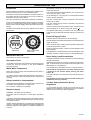
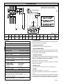
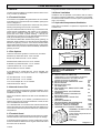
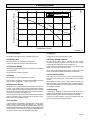
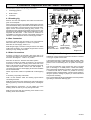
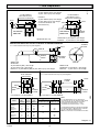
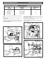
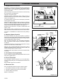
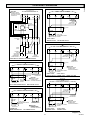
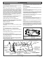
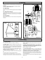
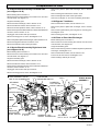
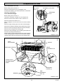
The boiler can be fitted with one of two makes of clock, which
look like this:-
6937
Clock / Timers
0
I AUTO
RUN P
13 12 11 1
0
19 18 17 1
6
20
7
24 23
22
Digital timer
1
MIN
R
Note. The boiler safety cutoff may have operated, please refer
to the following section to reset.
2
HR
3
21
5
DAY
Normal operation of the boiler should resume when the electrical
supply is restored.
6
P
The boiler will not work without an electrical supply.
4
W Th F S Su
8
M T
Electrical Supply Failure
I
9
15
14
PVC flexible cable having a conductor size of 0.75mm2 (24/
0.20mm) must be used within the boiler casing to connect to the
boiler.
Reset any external controls, to resume normal operation of the
central heating.
Electro / mechanical
clock / timer
The digital timer, has a lithium battery back up and will not need
resetting. Unless it is without power for a considerable period.
IMPORTANT NOTICE:
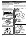
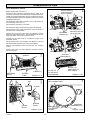
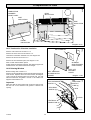
Boiler Safety Cutoff Reset Button
This boiler is for use only on G20 gas.
The boiler is fitted with a safety cutoff device to prevent damage
through overheating.
Gas Leak or Fault
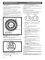
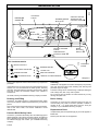
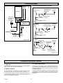
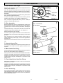
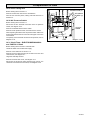
Should the main burner go out during a demand the red lockout
light “F” will illuminate on the control fascia situated above the
Reset Button “G”, see diagram 4.
If a gas leak or fault exists or is suspected, turn the boiler off and
consult your local gas company or your local installation/
servicing company.
The red light will not illuminate if there is no system demand.
Mains Water Temperature
Allow the boiler and system to cool down waiting at least
a minimum of four minutes before pressing the Reset
button “G”.
NOTE: The mains incoming water temperature in the winter is
lower than in summer.
The boiler will take a few seconds to reset after the button is
pressed.
To achieve the same outlet water temperature in the winter, it
will be necessary to reduce the water flow rate using the hot
water tap.
If the problem persists, turn the boiler off and consult your
installation/ servicing company.
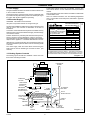
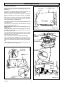
Boilers Installed in Compartments
If the boiler has been fitted into a compartment or cupboard, do
not obstruct the compartment air supply vents.
The Gas Safety (Installation & Use)
Regulations
Do not use the compartment for storage.
In your interests and that of safety it is the law that ALL gas
appliances are installed by competant persons in accordance
with the current issue of the above regulations.
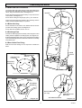
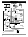
Electrical Supply
WARNING. The boiler must be earthed.
The boiler must be connected to a 230V~50Hz permanent
supply.
Connection of the whole electrical system of the boiler and any
heating system controls to the electrical supply, must be through
one common isolator.
Isolation should preferably be by a double pole switched fused
spur box. The fused spur box should be readily accessible and
preferably adjacent to the appliance. It should be identified as
to its use.
3
221895A