1
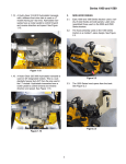
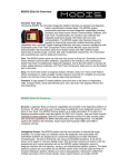
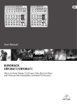
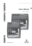
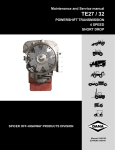
Chrysler and Jeep Reference
C1025
Subject:
Transmission changes for 1989-97 FWD vehicles with A604 (41TE and 41AE)
4-speed electronic transaxles
Source:
Chrysler training manuals
This revision outlines changes and improvements made to the A604 (41TE) front-wheel-drive
(FWD) 4-speed transmissions from 1989 through 1997.
1989 Model Year
Reaction Shaft Support
Early 1989 transaxles had reaction shaft supports with three sealing rings. The 3-ring support
was changed to a 4-ring support as a running change in February 1989. The 3-ring
configuration could cause clutch failures due to internal leakage between the underdrive and
overdrive circuits. The additional ring allowed the third and fourth seal rings each to perform a
single sealing function and provided dual venting to the sump.
Input Clutch Hub
The input clutch hub bore was deepened to accommodate a new reaction shaft support
length in February 1989. The revised input clutch hub (4531637) must be used with the
revised (4-ring) reaction shaft support.
The input clutch retainer was machined flat to allow more travel of the overdrive-reverse
piston (Figure C1025-1). The change occurred in February 1989.
Figure C1025-1
During 1989, the O-ring compression, or crush, was increased by making the hub O-ring
groove shallower to increase the sealing between the O-rings and the input clutch retainer.
The original black O-rings were replaced by orange and green Teflon-coated, tear-resistant
O-rings. Some remanufactured transaxles received light blue and yellow O-rings that had a
0.007 inch larger cross section than the original. The change increased O-ring compression
while still using the original hub.
C69
C1025
Chrysler and Jeep Reference
Transaxle Lip Seals
Some overdrive-reverse piston and input clutch hub outer lip seals were out of specification
(Figure C1025-2). Some 1989 and 1990 A604 Ultradrive transaxles may slip during 2-3
upshifts because of these seals. These seals can be found in other transaxle locations that
are within specifications. The seals were only dropped from overdrive-reverse piston and
input clutch hub outer lip seal applications. The seals can be identified by the marking “IPC.”
Figure C1025-2
Parking Sprag Guide Bracket and Pawl
The parking sprag bracket and pawl were changed in May 1989 from a stamped steel unit to
a precision cast unit (Figure C1025-3). The cast guide bracket reduced the effort required to
move the shift lever out of the park position.
Figure C1025-3
C70
C1025
Chrysler and Jeep Reference
Input Clutch Hub O-rings
In July 1989, the input clutch hub O-rings were changed from a 0.070" to a 0.103" cross
section, and the groove on the hub was deepened. This change was made to eliminate the
possibility of O-ring damage during installation. The latest O-rings are red and blue.
Low-Reverse Snapring Orientation
When installing the low-reverse reaction plate tapered snapring, be sure to follow the removal
or installation guidelines in the service manual for model years 1989 to the present
(Figure C1025-4). The ends of the snapring should be opposite the oil pan face and, when
installed, should be located under the case metal, not by the reaction plate lugs.
Figure C1025-4
Cooler Bypass Valve
An external cooler bypass valve was introduced in December 1989 to prevent potential
transaxle damage due to a lack of lubrication. Under very cold conditions, the transaxle fluid
may get cold enough to resist flow through the oil cooler and deprive the transaxle of
lubrication (Figure C1025-5). The valve was made an integral part of the transmission.
C71
C1025
Chrysler and Jeep Reference
Figure C1025-5
1990 Model Year
Overdrive-Reverse Piston
In July 1989, for 1990 production, the 8-slot OD-reverse piston and pressure plate were
upgraded to a 4-slot piston and pressure plate (Figure C1025-6).
Figure C1025-6
The OD-reverse piston orifice production procedure was revised in December 1989 for 1990.
The staking process and the length of the orifice assembly were changed to prevent reverse
and overdrive clutch failures due to orifice blowout or incorrect orifice installation
(Figure C1025-7).
C72
C1025
Chrysler and Jeep Reference
Figure C1025-7
Low-Reverse Piston Retainer
Transaxles that experienced a “stop bump” (harsh initial or coastdown engagement) condition
may have been the result of a high surface finish on the low-reverse clutch piston retainer.
This was discovered in February 1990. The out-of-specification surface finish of the retainer
could cause the low-reverse lip seal to wear and not energize until the TCM recognized that
the shift was not completed in the specified time (Figure C1025-8). The TCM would then turn
the solenoid controlling the low-reverse clutch circuit, to a fully on condition. This would apply
full line pressure to the clutch, and the result was the “stop bump” condition.
Figure C1025-8
C73
C1025
Chrysler and Jeep Reference
Transaxle Snaprings
In March 1990, the tapered snapring on the input clutch hub was modified for installation
purposes. The tab on the left side of the snapring was thickened to make sure that the
snapring was installed with the taper up (Figure C1025-9).
Figure C1025-9
Torque Converter
An additional improvement was made to the 10-inch torque converter by bonding friction
material to front cover for the 3.3L and 3.8L engines. This application was upgraded from a
9.5-inch converter to handle the increased torque load of the larger engines and was
introduced in June 1990. The part number is 4736076.
Input Clutch Assembly
In 1989 (for the 1990 model year), the input clutch and retainer were improved for durability
and quality. The overdrive clutch changed from a 3-disc, 2-separator-plate assembly to a
4-disc, 3-separator-plate assembly (Figure C1025-10).
Figure C1025-10
C74
C1025
Chrysler and Jeep Reference
PRNDL Switch
The internal contacts of the PRNDL switch were improved in January 1990.
Input Clutch Hub Bushing
The surface finish of the reaction shaft support journal could cause excessive wear of the
input clutch hub housing. The reaction shaft and the input clutch hub machining process was
revised in August 1990 to reduce wear.
Overdrive-Reverse Piston
The OD-reverse piston had material removed between the pressure plate snaprings. The
material was not needed, and the change reduced the weight of the OD-reverse piston and
allowed easier snapring installation. This change occurred during 1990 production.
Underdrive-Overdrive-Reaction Plate
The underdrive-overdrive reaction plate was revised as a running change in December 1990.
The new plate is different in appearance from previous plates. The new plate is fully
compatible with all other parts in the input clutch assembly. However, the plate must be used
with a matched snapring. A mismatch of these parts can cause the plate to move, resulting in
a 2-3 upshift shudder or a harsh 4-3 downshift.
Low-Reverse Clutch
When measuring to change low-reverse clutch pack clearance, a reduction in clearance
(0.035 inch) can improve 2-1 shift quality.
Piston Lip Seal
For 1990 and later, the underdrive clutch piston large outer lip seal is shallower. This lip seal
cannot be used with previous 1989 input clutch retainers.
1991 Model Year
Torque Converter
A damper assembly was added to the torque converter for the 1991 model year
Cooler Bypass Valve
An internal cooler bypass valve was introduced in July 1990 for the 1991 model year. It
replaced the external cooler bypass valve introduced in December 1989. The cooler bypass
is located in a bore in the pump face of the case. This can be recognized by a bump in the
case around the pump area near the cooler fittings. Always replace the bypass valve (part
number 4539880) during a transaxle overhaul.
C75
C1025
Chrysler and Jeep Reference
Transfer Shaft
Some early transfer shafts showed signs of torsional deflection under load in lab tests. There
were no field failures. A thicker transfer shaft was used to correct this condition and prevent
any possible pinion or ring gear failures (Figure C1025-11). The change occurred in July 1990
for the 1991 model year.
Figure C1025-11
Transaxle Case
The case was modified for the 3.3L all-wheel-drive (AWD) minivan in July 1990 for the 1991
model year. The extension housing was removed, and the case was machined flat for the
adapter plate installation. The adapter plate connects the transaxle to the power transfer unit.
The outer differential carrier bearing was enlarged to handle the increased load.
Input Shaft
The input shaft was changed from a 24-tooth spline to a 22-tooth spline. The change in the
number of shaft splines was made to accommodate a newly designed torque converter and
prevent incorrect assembly of the two components. The new torque converter also has a
damper assembly. The change covers the 1991-to-current models years.
Input Clutch Retainer
The input clutch retainer was changed to increase the depth of the reverse pressure plate
snapring groove by 0.5mm from 143.6mm diameter. There was no part number change. The
change occurred in early 1990 for the 1991 model year and was made to increase snapring
retention and to ensure proper installation during production.
Underdrive-Overdrive Reaction Plate
An induction hardening process was introduced for the underdrive-overdrive reaction plate for
the 1991 model year. The increased hardness improves plate and underdrive-overdrive
tapered snapring durability. The hardening process may cause the plate to have black or dark
lugs and a black or dark ring around the outer diameter of the part (Figure C1025-12). This is
C76
C1025
Chrysler and Jeep Reference
a normal appearance and is not to be confused with a damaged or burned plate. There are no
dimensional changes to the plate. The four select part numbers were not changed.
Figure C1025-12
Transaxle Friction Discs
Improved friction discs are available for the overdrive and 2-4 clutches on the AWD 41AE
production units and all clutches except the low-reverse for service units. The new friction
material was introduced as a running change during the 1991 model year.
Transfer Gears
New transfer gears were introduced as a running change in May 1991. The output and
transfer gear teeth have a new helix angle of 32 degrees to minimize gear whine. The
previous production output and transfer gear teeth were at a 27.5-degree helix angle.
The recessed area on the output transfer gear was eliminated to increase gear durability for
1991. The rear carrier output shaft is approximately 1/8-inch longer to accommodate the
revised output gear. The output gear bolt and transfer shaft nut now have a Loctite material on
the threads. The bolt and nut must be replaced whenever they are removed.
PRNDL Switch
If a vehicle built before May 1991 exhibits lighting of the backup lamps, clutch drag, slowing of
the vehicle, or vehicle shudder with the transaxle selector in overdrive, a faulty PRNDL switch
may be the cause. Diagnose and repair any trouble codes that may be present and then
follow the repair procedure for replacing the PRNDL switch. The new switch (July 1991) can
be identified by the antique bronze or olive-drab appearance of the switch housing.
Valve Body
A new valve body was released in May 1991 that contains aluminum spool valves for reduced
leakage throughout the temperature range. The earlier steel spool valves could potentially
C77
C1025
Chrysler and Jeep Reference
leak because of the difference in thermal expansion of steel valves in an aluminum housing.
The new valve body also contains a different converter clutch control valve that provides for
an electronically modulated converter clutch (EMCC). The old valve was referred to as the
lockup switch valve. In August 1991, a steel regulator valve was introduced to reduce the
tendency to buzz in reverse gear. A steel valve provides increased valve stability.
1992 Model Year
Separator Plates
In March 1992, a revised manufacturing process for the 2-4 separator plate, low-reverse
separator plate and UD-OD-reverse clutch separator was introduced to improve the quality
and durability of the plates and related parts. The new parts replace the old the old in service.
Differential Assembly
The AWD differential has a matched set of 59-tooth and 17-tooth gears for 1992 —59 teeth
for the ring gear, 17 teeth for the transfer shaft. The new AWD differential has a 2.49 overall
top gear ratio.
Transmission Control Module (TCM)
In 1992, a new TCM and valve body were introduced on 500 AY-body vehicles. The new TCM
allowed for electronically modulated converter clutch (EMCC) of the torque converter in 3rd
and 4th gears. The time the vehicle could be in EMCC mode had been extended for improved
fuel economy during city driving. Since that time, later software updates require disabling
extended EMCC operation because it will shear the transmission fluid and cause a
transmission shudder. It is recommended that the controller should be flash reprogrammed
with the latest software to eliminate extended EMCC operation. EMCC also is provided in 2nd
gear to minimize transaxle and engine overheating conditions.
Valve Body
Two changes were made to the transaxle valve body (Figure C1025-13) in 1992 to prevent a
reverse buzz condition.
• A 1 mm notch was cut into the valve body housing in the torque converter control valve
area in November 1991.
• A new valve body separator plate with reduced “T” and “Y” orifice diameters was
introduced in August.
Valve body repairs for 1992 models required replacement of either the valve body or the valve
body separator plate, depending on the build date of the transaxle. In August 1992, the
regulator valve was changed back to aluminum to provide for EMCC.
C78
C1025
Chrysler and Jeep Reference
Figure C1025-13
Chrysler Collision Detection (CCD) Bus
In 1992, vehicles began using the CCD bus system protocol. The protocol change is the
method of communication across the CCD bus. The TCM for 1992 and later vehicles will not
work properly if used on 1989–91 vehicles (Figure C1025-14). Service control modules with
improved features are available for 1989–91 models.
Figure C1025-14
C79
C1025
Chrysler and Jeep Reference
1993 Model Year
Oil Pump
A revised oil pump housing and a changed reaction support casting were released in July
1992 for the 1993 model year. The changes were made to extend the cavitation point of the
pump to higher engine speeds. The new pump assembly (part 4567862) can be used to
replace the older design.
Low-Reverse Piston
The low-reverse piston outer diameters were reduced by 0.04 inch to eliminate potential
thermal binding in the retainer. The casting tab was moved 1 mm (0.0394 inch). The part
number did not change, and the old and new parts are interchangeable. The change occurred
in July 1992 for the 1993 model year.
Extension Housing and Bearing Retainers
The speedometer pinion bore was removed from the extension housing in July 1992 for the
1993 model year. This eliminated the speedometer pinion, vehicle speed sensor, and
associated hardware. The transmission output speed sensor is used to send a vehicle speed
signal directly to the TCM. All 41TE transaxles now use the extension without the
speedometer bore, but the new extension cannot replace the old one on earlier
transmissions. The TCM is programmable with a “pinion factor” to calculate vehicle speed.
Accumulator Springs and Pistons
The inner accumulator spring was changed in July 1992 for the 1993 model year. The new
spring replaces the old spring with part number 4471881. The new spring is required in all
1993 model year low-reverse and 2-4 accumulators. The low-reverse accumulator is in the
case, and the 2-4 is in the valve body. The springs are shot peened and chamfered to
increase durability.
Some applications require a new outer spring (green) and a plain inner spring for the
underdrive spring only. The change improved neutral-to-drive shift quality. Part numbers are:
• Overdrive clutch outer accumulator spring — part number 4659124 (green)
• Overdrive clutch inner accumulator spring — part number 4567575 (plain)
Park Sprag Guide Bracket
The park sprag guide bracket was modified slightly for the 1993 model year to allow the
bracket to be common with the 42LE guide bracket (Figure C1025-15). The guide bracket
allows easier rod installation. The new guide bracket can replace the old design.
Oil Pump Seal
An orange ink coating was applied to the outer diameter oil pump seal in February 1993. The
coating prevents seal twist during production installation. A properly installed seal is easily
identified by the orange coating on one side of the seal. If the seal is twisted, black will be
visible instead of orange. There was no change to pump seal dimensions.
C80
C1025
Chrysler and Jeep Reference
Figure C1025-15
AWD Bearing Retainer
The all-wheel-drive (AWD) bearing retainer is made in two pieces since April 1993. An
additional O-ring on the outside diameter of the retainer is required with the retainer for
sealing purposes. The current O-ring, part no. 4486042, is carried over for this bearing
retainer assembly (Figure C1025-16). The new parts replace the old, and the part numbers
are as follows:
•
•
•
•
Transmission retainer plate — 47773735AB
Bearing Cone — 4567382
O-ring — 6500111
Overdrive Hub and Shaft
A faster machining process on the overdrive shaft spline was introduced in July 1993. The
new shaft can replace the old if a new front carrier also is used.
Rooster Comb and Insulator
The insulator tabs on the edge of the rooster comb were widened to accommodate the
electronic PRNDL display. The plastic insulator was modified to allow for wider tab slots and
was released in July 1993
Torque Converter
The torque converter clutch was changed to a bonded clutch disc from a free-floating clutch
disc to improve durability in November 1993 for the 10 inch converter and in April 1994 for the
9.5 inch converter.
C81
C1025
Chrysler and Jeep Reference
Figure C1025-16
Snapring
A new UD/OD reaction plate tapered snapring was introduced to improve durability. A new
UD/OD reaction plate (part numbers 456740, 641, 642, 643) is used to accommodate the
snapring. The new 0.16 inch snapring can replace the old if a new reaction plate also is used.
Differential Assembly
Two new gear tooth combinations were released for 1993 FWD and AWD differentials. The
matched gear set combinations are 59/17 and 60/16. The new differential assemblies can
replace the old. The matched set part numbers are:
•
•
•
•
FWD 59/17 — 4531990
AWD 59/17 — 4531996
FWD 60/16 — 4531993
AWD 60/16 — 4531999
A differential assembly with high intensity shot peening to improve durability also was
released in 1993. It is used with 3.8L engines. To identify, look for two grooves in the side of
the differential ring gear (Figure C1025-17) and one groove in the side of the pinion gear on
the transfer shaft. The part number for the matched set is 4659178 with a ratio of 60:16.
TCM Pinion Factor
When installing a replacement TCM for 1993 and later model years, it is necessary to set the
“pinion factor”. Use the scanner and select the proper axle ratio to set the “pinion factor” so
that the speedometer indicates correct mph.
C82
C1025
Chrysler and Jeep Reference
Figure C1025-17
TCM Quick Learn
The quick-learn function applies to all 1993 and later vehicles with the 41TE transaxle if
flashed properly. This option is not available for earlier vehicles. Introduced in 1993, the
quick-learn function customizes, or adapts, the TCM to the particular characteristics of the
vehicle transaxle. Quick learn provides improved initial shift quality after transaxle or TCM
service, compared to the initial programmed parameters stored in the TCM. The quick-learn
function should be performed under the following conditions:
• Upon installation of new TCM
• After replacement or rebuilding of internal transmission parts or the torque converter
Transaxle Symptom — Harsh Shifts
Harsh engagement occurs with tip-in during low-speed 2-1 downshifts, low-speed harsh 2-1
kickdown shifts, harsh 3-2 and 4-3 coastdown shifts, harsh 3-4 upshifts, harsh stationary
neutral-drive shifts, park-to-reverse noise (grunt) in 1993 FWD vehicles and some 1994
vehicles. Use the scanner to diagnose and repair any diagnostic trouble codes or service any
engine or transaxle related problems. If no codes are present and all systems are functioning
properly, replace the TCM, change the transmission fluid, set the pinion factor in the TCM,
and perform a transaxle quick-learn procedure.
Transaxle Gear Retaining Strap
Beginning in November 1993, 41TE transaxles used with the FWD 3.8L engine or AWD
minivan have a stirrup (part 4567263) and retaining strap (part 4659134) attached to the
output gear with two bolts (part 6503355, Figure C1025-18). The stirrup, strap, and bolts
prevent the output gear retaining bolt from turning and backing out of the rear carrier. These
C83
C1025
Chrysler and Jeep Reference
additional output gear retaining parts are required because of the additional thrust loads from
the new, quieter 32-degree helix-angle transfer gears and the high-output 3.8L engine.
Figure C1025-18
Owner’s Manual Changes
The transmission gear selection and operating instructions in the owner’s manual for all
vehicles with automatic transaxles or transmissions were revised in 1993 to provide more
precise transmission control, to explain the advantage of engine braking on grades, and to
reduce the chance of engine overheating. The revised instructions are as follows:
• Park (“P”) — Supplements the parking brake by locking the transaxle. Engine can be
started in this range. Never attempt to use PARK while vehicle is in motion. Apply parking
brake while leaving vehicle in this range.
• Reverse (“R”) — Shift into this range only when the vehicle has come to a complete stop.
• Neutral (“N”) — Engine may be started in this range. Use this range for starting your
vehicle if it is moving or being towed.
• Overdrive (“OD”) — This range should be used for most city and highway driving. It
provides smoothest upshifts and downshifts and the best fuel economy.
• Drive (“3”) — This range should be used for descending hills. The shift schedules in this
range provide improved engine braking and vehicle performance at the expense of fuel
economy. The transaxle will not shift into overdrive when this range is selected. Under
certain conditions, this eliminates frequent shifting between third gear and overdrive.
• Low (“L’) — This range should be used for maximum engine braking when descending
steep grades. In this range, upshifts will occur only to prevent engine overspeed while
downshifts occur as early as possible.
C84
C1025
Chrysler and Jeep Reference
1994 Model Year
Front Carrier Assembly
A new overdrive shaft for 1994 required that the front carrier hub internal spline be recessed
for overdrive shaft clearance. The shaft and front carrier were changed in July 1993 for the
1994 model year. The bearing pocket in the front carrier was made larger and deeper to
accommodate the common no. 2, 5, and 7 thrust bearings (Figure C1025-19). The new
carrier replaces the old.
Figure C1025-19
Thrust Bearings
The no. 2, 5, and 7 thrust bearings became common in July 1993 for the 1994 model year,
figure 19. This reduced the number of bearing assemblies required for the no. 2, 5, and 7
positions. Previously, two part numbers were used. The new thrust bearing part number is
4567262. The old part numbers were 4431962 for the no. 2 and 5 bearings, and 4412209 for
the no. 7 bearing.
Valve Body
A new valve body and transfer plate assembly were introduced in July 1993 for the 1994
model year to eliminate valve body whistle. The regulator valve was modified to add a ground
step diameter for full-time oil feed to the torque converter. The valve body steel separator
plate has the X1 orifice eliminated (Figure C1025-20).
Snapring
The UD/OD reaction plate tapered snapring uses a new material for improved durability. The
change was effective in April 1994 with no part number change.
C85
C1025
Chrysler and Jeep Reference
Figure C1025-20
1995 Model Year
Input Clutch Hub
A dirt collection groove was added under the input clutch hub lip seal groove to improve
durability. The underdrive clutch feed orifice in the input clutch hub also was reduced in size to
minimize the UD clutch cavity transient pressure loss. The change improved shift quality and
occurred for the 1995 model year. The part number is 4531637.
Overdrive-Reverse Piston
For the 1995 model year, the bottom of the OD-reverse piston slots where the OD-reverse
pressure plate fits was given a D-shaped cutout (Figure C1025-21) to allow better oil flow and
reduce powdery debris buildup that could affect lip seal function.
Overdrive-Reverse Clutch Pressure Plate
The OD-reverse clutch pressure plate material was changed for 1995 to improve durability.
The pressure plate can be identified by a dimple in one of the drive hubs. The part number is
5017518AB.
Underdrive Clutch Hub and Shaft Assembly
The underdrive hub and shaft assembly has an added step to eliminate burrs caused by the
face grinding process. Added clearance for a redesigned spring pack also was provided.
C86
C1025
Chrysler and Jeep Reference
Figure C1025-21
2-4 Clutch Piston Retainer
A lance-bleed orifice was added to the 2-4 piston retainer to improve shift quality in 1995. The
new retainer part number is 5102880AA.
Piston Lip Seals
The underdrive clutch piston inner lip seal material was changed for 1995. The new seal
replaces the old one.
The low-reverse piston lip seals also were revised in 1995. The new lip seals are D-shaped
rings to improve installation during production. The new seals service the old.
Differential Case, Side Gears, Seal Retainer, and Extension Housing
The differential side gears and the differential case for the 41TE were modified to accept
circlips on the axle shafts for 1995. This improved axle shaft retention and overall quality. The
inside diameters of the oil dams in the differential bearing retainer and extension housings
have been increased to accommodate the axle shafts with the circlips. The change began
with production for the 1995 model year. Part numbers for the oil dams are as follows:
• Left oil dam — 4567493 (new), 4269787 (old)
• Right oil dam — 4567494 (new), 5222255 (old)
The differential bearing retainer seal for some models also was changed for 1995. The new
part number is 4567496 (green) to replace 4412522 (old — blue). For servicing, the new seal,
part number 4762418 (green), must be used so that the current special tool can be used
without damage to the seal.
C87
C1025
Chrysler and Jeep Reference
Some transaxles require a short aluminum extension housing (Figure C1025-22) part number
4567337. The old extension housing part number is 4567412.
Figure C1025-22
Transaxle Covers
The outside contour of the differential cover was revised for added vehicle clearance in July
1993 for 1994 models. The differential gear cover was revised for 1995 in preparation for the
rear mount. The wiring tab also was moved to provide additional clearance for the new
Minivan. The transfer gear cover was raised to accept the stirrup and strap retainer for the
output bolt (Figure C1025-23). The transfer gear cover outside contour and the gear pockets
were revised to accommodate new axle shafts and new ratio transfer gears on future models.
Figure C1025-23
C88
C1025
Chrysler and Jeep Reference
The new covers can replace the old. The part numbers below for the differential cover are for
the 1995 model year.
• Differential cover — 4659520 (new), 4659093 (old)
• Transfer gear cover — 4659636 (new), 4567255 (old)
1996 Model Year
Transmission Range Sensor (TRS)
The transmission range sensor (TRS) is located on top of the valve body. The TRS replaces
both the gear position switch and the transmission range switch to provide transaxle gear
position measurement.
A separate transmission temperature sensor, located inside the TRS, measures transmission
fluid sump temperature. The temperature sensor is serviced with the TRS as a unit.
The TRS sends a signal to the TCM on the position of the transaxle manual valve lever. The
TCM receives the signal and processes the data. The TCM sends the shift lever position
(SLP) information to the body control module (BCM) over the CCD bus. The BCM then lights
the appropriate shifter position indicator in the instrument cluster.
Transaxle Case Mounting
The 41TE transaxle for 1995-1/2 has a 4-point engine-to-transmission mounting system.
Earlier models used a 3-point mounting. The casting change (3 bosses on top of the
differential case) was made early in 1995 for 3.3L engines. This casting change also affected
some past models with ABS.
The 3.0L case does not get the fourth mount, and the 2.2L and 2.5L case castings have
always had the fourth mount.
• 3.3L and 3.8L case part numbers — 4567013 (3 mount), 4567533 (4 mount)
• Case casting part numbers — 4539572 (3 mount), 4567534 (4 mount)
Upgraded Differential
The differential was changed to improve durability of the left side differential bearing. The
changes are listed below:
• Differential bearing retainer — Bearing bore increased in diameter for larger bearing.
Flange thickness was also increased by 2mm.
• Differential bearing retainer bolt — Longer bolt and a 360-degree patch to seal the holes
tapped through the case.
• Cup and cone — Larger diameter left side differential bearing cup and cone.
• Oil dam — Left side bearing baffle to match the bearing cone.
• Select differential bearing retainer shim — Select-fit differential bearing shims for
adjusting bearing preload.
• Case — Tapped for the longer differential bearing retainer holes bolts.
• Differential assembly — Differential hub size change to accommodate the larger bearing.
• Reduced differential backlash.
C89
C1025
Chrysler and Jeep Reference
Valve Body Improvements
Several changes were made to the valve body for 1996 on 41TE transaxles. The major
changes were the addition of two new valves:
Low-reverse switch valve — This has taken the place of the no. 1 check ball to provide a
more positive design and to avoid the possibility of a sticking check ball. In pre-1996 designs,
the check ball tended to stick, so the new switch valve was necessary.
Torque converter limit valve — The X1 orifice was eliminated, and a small undercut was
machined into the limit valve to provide a constant bleed to the converter.
Additionally, the torque converter control valve was modified to delete the function of
regulating the flow to the torque converter when the converter clutch is not applied. The
modification was made to reduce the sticking tendencies that could occur when fluid from the
torque converter was routed through the valve. The valve switches the direction of fluid flow
when the converter clutch is applied and vents the release side of the torque converter clutch.
Overdrive Shaft
A thicker overdrive shaft was added for improved strength along with a thin-wall shaft bushing
and a thinner wall front sun gear bushing. When replaced together, the new overdrive shaft
assembly and sun gear assembly can replace the old.
Rear Carrier
Changes to the cup and plate of the rear carrier allowed a stronger, 360-degree weld instead
of the previous segmented weld.
1997 Model Year
The reaction plates were reduced from four to three plates. The tapered snapring and flat
snapring on either side of the UD/OD clutch were increased in size to 0.015 inch. Therefore, a
sleeved reaction shaft support was added and the input clutch retainer was revised.
The cover assembly also was modified to be a “sandwiched” cover that consists of a layer of
metal, then a layer of plastic, and then metal. This change helped reduce transfer gear noise.
C90