1
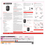
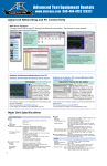
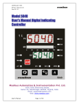
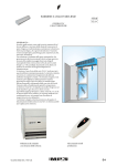
1
DRAFT
OSKRG Research/Restoration Bulletin #2
52-71 Linkert/Tillotson Carburetors
This research and restoration bulletin was created with input and
assistance from members of the OSKRG. The report consolidates
the best available information at the time of creation and may be
updated or revised at a future date. If errors are identified, or
there is additional information on the subject of this report that
has not been included, please send corrections or additions to:
[email protected] & [email protected]
© 2014 By OSKRG
2
Forward
As the opening statement on page 1 states “This research and restoration bulletin was created with input and
assistance from members of the OSKRG. The report consolidates the best available information at the time of
creation and may be updated or revised at a future date. “This work is by no means definitive. A realistic
expectation of this work would be that there are going to be errors but at least it is a place to start the
conversation from. Consider this bulletin to be a living thesis, as empirical evidence presents itself this document
will be modified to more accurately reflect what was original equipment on the Ks & Sportsters from 1952 through
1971. It addresses the M53 Linkert series, the DC Linkerts and the Tillotsons. There are a number of models and
years that remain an outright mystery like what production bike was the M53A Linkert carb used on if any at all to
areas that might be considered “gray” like what models and years was the DC-1L used on and when did Harley stop
using the DC-10 and start using the DC-12. If you have a bike that you are confident has its original carb on it we
would love to hear from you. Within the document we have a “score card” of sorts to track what carb people have
on their original bikes, this score card can serve as an important validation tool. Hopefully over time we can mold
this document into a valuable tool to help enthusiast in their restoration efforts.
© 2014 By OSKRG
3
Table of Contents
Forward
Page 2
Section 1, 52-56 Linkert Carburetors:
Page 3:
Carburetor Model, Carburetor Part Number, Jet Diameter/Number & Year
What Is Actually On Your Bike-Please Let Us Know
Page 4:
Linkert 53 Series Notes & Pictures
Section 2, 57-65 DC Linkert Carburetors:
Page 5:
DC Linkert Carburetor Model, Bike Type, Model Year & Comments
Page 6:
DC Linkert Carburetor Model, DC Linkert Carburetor Part Number, Jet Diameter/Number & Comments
Page 7:
What Is Actually On Your Bike-Please Let Us Know
Pages 8 & 9:
DC Linkert Series Notes & Pictures
Section 3, 66-71Tillotson Carburetors:
Page 10:
Tillotson Carburetor Model, Tillotson Carburetor Part Number, Jet Diameter/Number & Comments
Page 11:
What Is Actually On Your Bike-Please Let Us Know
Page 12:
Tillotson Series Notes & Pictures
© 2014 By OSKRG
4
Section 1
52-56 K Model Linkert Carburetors
Green Indicates Some Degree of Confidence Carb was Original Equipment Yellow Indicates Some Uncertainty
R10
Linkert Carburetor Model
Part Number
Jet # & Dia.
1952
1953
M53
27146-52
#8 ( ) or #9 (.067)
K
K & KK
1954
1955
1956
Comments: The bombsight venturi on the M-53 is 1 ¼” so it won’t fit the later 53-A1 carb but it will fit on an earlier 1 ¼’ body. Both carbs still use the
flathead style bowl though, which is different from the Panhead version as the float lever and needle and seat housing is offset and not “in line” as on the
OHV carbs. In other words the bowl gasket on sidevalve carbs are an “O” and the bowl gasket on OHV carbs has two “O”s, one big, one small. (Scott.L.)
M53-A
KH & KHK
Comments: M53A exists, application unknown, perhaps a transitional model between the M53 and M53A1.
M53-A1
27146-52A
#8 ( ) or #9 (.067)
KH & KHK
KH & KHK
KH & KHK
Comments: The M-53A1 carb has a full size venturi just like the Linkert M-74B used on panheads, 1 ½” standard open venturi and no bombsight. Both
carbs still use the flathead style bowl though, which is different from the Panhead version as the float lever and needle and seat housing is offset and not
“in line” as on the OHV carbs. In other words the bowl gasket on sidevalve carbs are an “O” and the bowl gasket on OHV carbs has two “O”s, one big, one
small. (Scott.L.)
© 2014 By OSKRG
5
52-56 Linkert Carburetors
Linkert Carburetor Significant Part Number Changes from Parts Book to Parts Book vs.1
Note: A column Part Number Color Change Indicates a Part Number Change. Text in Red Indicates What the part is Supposed to Fit has Changed.
Parts
Book
Year
Carburetor
Complete
Part
Number
Linkert
Carburetor
Model
1953 PB
1954 PB
1956 PB
27146-52
27146-52A
27146-52A
M-53
M-53A1
M-53A1
What Is Actually On Your Bike-Please Let Us Know
1952
Linkert Model
M53
M53-A
M53-A1
OTHER
© 2014 By OSKRG
K
1953
K
1954
KK
KH
1955
KHK
KH
1956
KHK
KH
KHK
6
Linkert 53 Series Notes & Pictures
M53 Carburetor
M53A Carburetor
Air intake, M-53A on left, M-53A1 on right. You can see the
one piece choke lever assembly
© 2014 By OSKRG
M53A1 Carburetor
Air intake, M-53. Note two
piece choke lever. Lever
part very hard to find.
7
Linkert 53 Series Notes & Pictures
Manifold end, M-53. Note offset fuel
intake on all M-53 models.
Manifold end,
M-53A.
Manifold end,
M-53A1.
These are obviously unrestored carburetors. The high and low speed adjustment needle controls should be cad plated, also the
bowl nut, throttle control components.
M-53A1 with some
of original black
paint remaining.
Manifold end,
M-53A1.
© 2014 By OSKRG
8
Top down view, M-53A1. This
was complete take-off unit,
including air cleaner and
intake manifold in
background. Note manifold is
parkerized finish, manifold
nuts are cad plated.
M-53A1, air cleaner
assembly side.
Scott L. Additional comments about the Linkert finishes:
“I would confirm Roger’s observation re: black paint. Bruce Palmer’s book confirms this on the Panhead models, including the M-74B. They are
not hard to paint. I put on a crappy bowl, then set the ends on the sticky side of contact paper, then use an exacto knife to trace around the
outline of the end openings, and then spray away. Interesting thing I have been reading as I have been researching all finishes for the Linkerts. The
finishes used (zinc dichromate, silver cad, and even the black paint) all seem to break down fairly quickly at temperatures above 120
degrees. Sitting between the cylinders of an air cooled motorcycle puts temps well above that threshold and would explain why the finishes are
almost always evenly worn off on used Linkerts.”
© 2014 By OSKRG
9
Section 2
57-65 DC Linkert Carburetors
Green Indicates Some Degree of Confidence Carb was Original Equipment Yellow Indicates Some Uncertainty
R10
Linkert
Carburetor
Model
1957
XL
1958
XL
XLH
1959
XLCH
XL
XLH
1960
XLCH
XLH
XLCH
1961
XLH
XLCH
1962
XLH
XLCH
1963
XLH
XLCH
1964
XLH
XLCH
1965
XLH
XLCH
DC-1 Open Vent
Comments: 27155-57. Open Vent. The early versions (pre-1960 or so) don’t have the patent numbers on the bowl.
Later versions have a patent number. 1 year only choke lever for 57.
Theorizing HD used same part number for all DC-1 models. 1957 version of DC-1 used washer 6187 in throttle lever assembly, replaced in 1958 by 6182.
DC-1 Closed Vent
Comments: 27155-57A. Closed Vent, XL-XLH.
1959 parts book indicate the female thread float valve assembly (27382-57) was changed to the male hose barb float valve assembly (2738257A) in mid-1958. Change from open vent (27343-57) to closed vent (27343-57A), and main jet (27317-57 - #9 @ .067) to (27317-57A - #4 @ .0625) occurred at or around the same time.
DC-1L
Comments: Believed to have been used on all 1958 high compression models, though not positively confirmed. The DC-1L is the same carburetor as the reconfigured DC-1 used in mid-late
1958.
DC-10
Comments: 27155-57A.
Same carburetor as the reconfigured DC-1 except model stamp. All models. Control wire block screw 1058W replaced 1063 in 1961; throttle lever stop screw
1073W replaced with 1074W in 1961. 1963 Service Manual suggests DC-10 still in use through 1962, though many original 1961 bikes are observed to have DC-12 carburetors.
DC-12
Comments: 27155-57B.
Improved float valve assembly (27382-61). Second opening added to needle housing, needle tip cut off leaving only enough bevel to seat when closed. Control
wire block screw 1058W replaced 1063 in 1961; throttle lever stop screw 1073W replaced with 1074W in 1961. 1963 Service Manual suggests DC-10 still in use through 1962, though many original
1961 bikes are observed to have DC-12 carburetors. Early versions of DC-12 had flat surface @ inlet hose barb, later versions had recessed surface @ inlet hose barb. Late versions of DC-12 have
brass “anti-sprattle” plate to reduce spillage through overflow vent. Used on 1964 XLA.
DC-6
Comments: 27155-57B.
Observed on several original 1965 models. Believed to be replacement version of DC Linkert series, introduced around 1965 and installed interchangeably with DC12 on late 1965 models. Believed to have brass “anti-sprattle” plate.
1957
1958
1959
1960
1961
1962
1963
1964
1965
1966
DC-2
Comments: Service cars
DC-1M
Comments: XLA. The DC-1M is the military version.
It is powered down as the military spec for the XLA was a 750CC motorcycle. Same as 27155-57 with #1 main jet @ .052.
Shovelhead
DC-7
Comments: 1966 Shovelhead.
Same as 27155-57B, with #45 main jet @ .070.
DC-11
XLR
Comments:
Multiple DC Linkerts stamped DC-11 observed with same float valve assembly used on K model Linkerts (27382-52) with 3/8 UNF male threaded inlet to accept 3/8” 90 degree hose
inlet elbow used on competition models. Competition manuals suggest the DC-11 was a carburetor option for the XLR.
DC-3, DC-4, DC-5,
DC-8, & DC-9.
Comments: No documentation of these models.
custom applications.
© 2014 By OSKRG
Some Linkerts stamped with these numbers believed to be blank bodies stamped by someone other than Linkert or Harley-Davidson for
10
57-65 DC Linkert Carburetors- Contradicting Opinions
Green Indicates Some Degree of Confidence Carb was Original Equipment
Yellow Indicates Some Uncertainty-Red Indicates Other Sources Assertions
Linkert Carburetor
Model
1957
XL
1958
XL
XLH
1959
XLCH
XL
XLH
1960
XLCH
XLH
XLCH
1961
XLH
XLCH
1962
XLH
XLCH
1963
XLH
XLCH
1964
XLH
XLCH
1965
XLH
XLCH
DC-1 Open Vent
DC-1 Closed Vent
DC-1 Other Source
Rational for our assertions: Based primarily on a number of original paint unmolested bikes.
DC-1L
DC-1L Other Source
Rational for our assertions: Based primarily on a number of original paint unmolested bikes.
DC-1M
DC-1M Other Source
XLA
1960 XL
Rational for our assertions: Shop dope bulletin clearly states the DC-1M was for the 1957 XLA. XL only produced in 57, 58 & 59 per “Legend Begins” book.
DC-10
DC-10 Other Source
Rational for our assertions: Based on a number of original paint unmolested bikes & extensive research of service manuals and parts books.
DC-12
DC-12 Other Source
Rational for our assertions: We have tracked the parts books very carefully – we have detailed the configurations of fixed jets and needle and seat assemblies
and pinned down the dates of changes. The earlier service manuals do not show the DC-6 and DC-12 models, indicating they were later versions.
DC-6
DC-6 Other Source
Rational for our assertions: We have tracked the parts books very carefully – we have detailed the configurations of fixed jets and needle and seat assemblies
and pinned down the dates of changes. The earlier service manuals do not show the DC-6 and DC-12 models, indicating they were later versions.
1957
1958
DC-2
DC-1M
1959
Service Cars
Non XL, XLH & XLCH Models
1960
1961
1962
1963
1964
1965
1966
XLA
Shovelhead
DC-7
DC-11
Comments:
XLR
Multiple DC Linkerts stamped DC-11 observed with same float valve assembly used on K model Linkerts (27382-52) with 3/8 UNF male threaded inlet to accept 3/8” 90 degree hose inlet
elbow used on competition models. Competition manuals suggest the DC-11 was a carburetor option for the XLR.
DC-3, DC-4, DC-5,
DC-8, & DC-9.
Comments: No documentation of these models.
© 2014 By OSKRG
11
57-66 DC Linkert Carburetors Part Numbers, Sizes & Thicknesses
Yellow Indicates Some Uncertainty
Linkert Carburetor
Model
DC-1 Open Vent
Part Number
27155-57
Jet # & Dia.
#9
.067
Throttle Disc
9A
Comments: Open Vent. The early versions (pre-1960 or so) don’t have the patent numbers on the bowl.
same part number for all DC-1 models
DC-1 Closed Vent
Throttle Body
Thickness @ Bolt
Holes to Manifold
.219”
Throttle Body
Opening Diameter
1.375”
Later versions have a patent number. 1 year only choke lever for 57. Theorizing HD used
#9
.067
9A
.219”
1.375”
#4
.0625
9A
1.375”
#4
.0625
9A
1.375”
#4
.0625
9A
.281”
1.375”
27155-57B
#4
.0625
9A
.281”
1.375”
Part Number Unknown
#20
.0452
12
.219”
1.0625”
Comments: Closed Vent , XL-XLH
DC-1L
Comments: XLCH
DC-10
27155-57A
Comments: XLCH
DC-12
Comments: XLH-XLCH, 64XLA
DC-6
Comments:
DC-2
Comments: Service cars
DC-1M
Comments:
DC-7
#1
.052
XLA. The DC-1M is the military version. It is powered down as the military spec for the XLA was a 750CC motorcycle.
Part Number Unknown
#45
9A
.281”
.070
Verified -66PN for #45 Jet
1.375”
Comments: Early Shovelheads 1966
DC-11
Comments:
DC-3, DC-4, DC-5, DC-8, & DC-9
Comments:
No documentation of these models. Some Linkerts stamped with these numbers believed to be blank bodies stamped by someone other than Linkert or Harley-Davidson for custom
applications.
© 2014 By OSKRG
12
57-65 DC Linkert Carburetors
DC Linkert Carburetor Significant Part Number Changes from Parts Book to Parts Book
Vs.3 Note: The pictures in some cases do depict the part accurately, in others they don’t. The intent of their inclusion is more for reference.
Parts
Book
Year
Comments/Changes
57 PB
58 Year
59 PB
60 Year
61 Sup.
62 Sup.
27433-57 Carb Support
Bracket 57-59 XL & XLH.
27433-58 Carb Support
Bracket 58-59 C & CH
New parts for
61*Carburetor:
•
Control wire
block screw
•
Throttle
control bracket
screw
•
Support nut
•
Throttle
control bolt
clamp
Same as 61 Comments in
addition carburetor
throttle lever stop screw
& spring PN 27270-49
replaced by 27270-49A
63 PB
65 PB
© 2014 By OSKRG
Carburetor
Complete
Part
Number
Possible DC
Linkert
Carburetor
Model
Carburetor
Matched
Float Valve
& Seat
Carburetor
Jet
Carburetor
Nozzle Vent
Housing
Assemble
Tube-Idle
Bleed
Throttle
Disc
High Speed
Needle
Valve
27155-57
DC-1
DC-1L
DC-1M
27382-57
27317-57
27343-57
Not
Present
27280-57
27297-57
27331-57
27324-57
27339-57
27155-57A
DC-10
27382-57A
27317-57A
27343-57A
27280-57
27297-57
27331-57
27324-57
27339-57
DC-6
&
DC-12
27382-61
27280-57
27297-57
27331-57
27324-57
27339-57
27280-57
27280-57
27297-57
27297-57
27331-57
27331-57
27324-57
27324-57
27339-57
27339-57
27155-57A
27155-57B
27155-57B
27382-61
27317-57A
27155-57B
27155-57B
27382-61
27382-61
27317-57A
27317-57A
27343-57A
27343-57A
Carburetor
Main Nozzle
Idle Tube
Assemble
Low Speed
Needle
Parts Never Changed
27322-58
27322-58
13
57-65 DC Linkert Carburetors
What Is Actually On Your Bike-Please Let Us Know
1957
1958
DC Linkert Model
XL
XL
DC-1 Open Vent-90’
Gas Inlet
1
2
XLH
1959
XLCH
XL
XLH
1960
XLCH
XLH
1961
XLCH
XLH
1962
XLCH
XLH
1963
XLCH
XLH
XLCH
1964
1965
XLH
XLCH
XLH
XLCH
1
2 & 1 XLA
1
1
DC-1 Open VentStraight Gas Inlet
DC-1 Closed Vent
1
DC-1L
DC-10
1
DC-12
DC-7
DC-2
DC-4
DC-11
DC-Other
© 2014 By OSKRG
3
1
1
1
DC-6
DC-1M
1
1
1-XLA
1
1
2
14
DC Linkert Series Notes & Pictures
Early & Late Float Bowls, Common Carb Bodies, Open & Closed Vent & Anti-Splash Plate
© 2014 By OSKRG
15
DC Linkert Series Notes & Pictures
5 Needle & Seat/Fuel Inlet Combinations
© 2014 By OSKRG
16
DC Linkert Series Notes & Pictures
Documented -57A & -61 Needle & Seat/Fuel Inlet Combinations
© 2014 By OSKRG
17
DC Linkert Series Notes & Pictures
Different Thickness Throttle Bodies
2 Different Throttle body Thicknesses with the Same Part Number. The One on the Left is about 1/16” Thinner.
© 2014 By OSKRG
18
DC Linkert Series Notes & Pictures
XLCH Gas Tank Fuel Strainer & Outlet & Carburetor Fuel Inlet Fittings
Help with this topic, here are comments you made on the subject Scott & pictures you sent.
. The 1958 XLCH used the DC-1L, with mid to late bikes having the dual nylon hose barb fitting, one coming out of the female float valve inlet fitting and the other
coming out of the fuel tank strainer. By 1959, all models came with the DC-10, with the -57A float valve assembly and straight hose barb inlet. All 1960 models also
had the same DC-10 configuration. In 1961 the -61 float valve assembly was introduced, designated DC-12. This is the dual notch, chopped needle tip version of the
needle and seat with straight hose barb inlet. We determined the DC-11 was a racing version for the XLR. It has a male threaded float valve assembly inlet and
appears to be the same assembly as used on K model carburetors. The 90 degree, 3/8” inlet elbow from the -54R strainer and hose kit fits onto the threaded float
valve inlet and connects to a 3/8” inside diameter fuel line.
© 2014 By OSKRG
19
I also dug through all my -54 strainers and lo and behold I found a used one with the metal hose barb, 62378-52, still installed. When I talked to Bill Morris today he
said he will check his 1971 XLCH to see what is coming out of the fuel tank strainer. If the fitting there is nylon, I will defer to Roger on 62374-58. If it is metal, I will
instead continue to think the nylon version of the strainer outlet valve had a very limited application to 1958 and very early 1959 only. When I spoke with Bill today he
confirmed he knew 100% of the history of the 1961. He has had offers up to $30K, but won’t sell it specifically because, as he put it “that bike has been a part of his life
for over 50 years.” Whatever is on the fuel tank strainer on that bike is what the factory put there when they built it.
I am intrigued by the plastic/nylon gas fitting. I am going to assume it is nylon rather than plastic as plastics from the time didn’t have the same properties as modern
fuel resistant properties. I have never seen a strainer with the nylon fitting installed nor have I come across a needle and seat assembly with the nylon barb seated in
the female threaded inlet. I see your point though about the parts book. I also looked at the -63 parts book which indicates 62374-58 replaced the 90 degree elbow in
late 1958 to 1961. I also looked at the oil tank group and see that item 63578-52 appears to be the part number on the smaller 5/16” fittings that I have routinely seen
in the strainers I have come across. The use of 63578-52 seems logical given that it is the identical fitting to 63533-41 in the racing strainer kit, only smaller to fit the
smaller stock size fuel line. In my parts book analysis I noted that it appears that around 1959 the needle and seat assembly was changed from the early female version
to the male hose inlet version. We must assume this was done on the XLCH as well as the other models, which would mean only one 62374-58 would be needed for
the strainer outlet rather than two. Yet, the 1963 parts books still call for two from late 1958 through 1961. The parts book simply can’t be right here. Once again, I’m
skeptical that we can rely completely on the parts book to reach conclusions on this. That said, there is a period from mid 1958 to perhaps early 1959 when the early
female inlet needle and seat was used without the 90 degree elbow where a nylon fitting may have been used. My guess is that if that is the case it the nylon fittings
were not used on many bikes. Note the 1959 parts book was issued on September 1, 1958 around the time the new 1959 models were rolled out. The -57A needle
and seat assembly was specified for all Sportster models. It is hard to see a window other than mid 1958 to rollout of 1959 where the nylon fitting would have been
used with the -57 version of the assembly. Makes me wonder – is your 1959 a really early one possibly produced before September 1, 1958? If so, maybe you have a
pretty rare bike where a transitional part was used. I have an early 1965 XLCH with the early version of the horn mount bracket. I have looked high and low for
another of these horn mounting brackets and have never seen one anywhere. Perhaps you have a similar anomaly?
I found a needle and seat assembly in my parts pile that was in the old brown envelope with the early black ink logo and parts markings. I looked inside and noted that
the early -57A needle and seat assembly came with the hose, which had the same inside diameter but had a much smaller outside diameter than the later version of
the hose which appears to have been introduced in 1959. The XL and XLH models may have had the thicker hose from ’57 through ’59 because the clamp 9998 fits that
hose but is too big for the smaller diameter XLCH hose used in 1958. Intuitively, it seems the smaller version of the hose would connect well with the nylon barb fitting
in the photo you sent.
That said, the rarity of the nylon barb, along with the fact that nylon was in its infancy at the time, causes me to be a bit cautious. A parallel in time is the use of the
ESNA (Elastic Stretch Nut of America) or nylock fasteners. Until 1957, Harley had been using the metal tension nuts then changed over to the wine colored ESNA nuts
in 1957 (the invention was patented by ESNA and the wine color was proprietary and protected by patent. That is why early nylock fasteners are incorrect on
restorations of the period and why knowledgeable restorers will use RIT dye to recolor clear fasteners to look like an early ESNA product.) In any event, it makes sense
Harley may have used a nylon fuel fitting in 1958 and 1959 and even up to 1961, but I still find it very hard to understand why there are none out there today. It seems
there should be some left in NOS inventory. I am going to call Bill Morris later today to see if he has come across any of these, whether they are on his all original 1961
XLCH, and whether he has any in inventory. Of course I will let you know what I find out.
Not sure if you noted in the photos I sent there was one shot of the 90 degree racing inlet fitted to the early female needle and set and right next to it was an
unexplained needle and seat assembly where the inlet barb was soldered into a female threaded fitting. This might have been a precursor to the later style needle and
seat assemblies introduced around 1959. I still have no explanation for that version of the needle and seat.
© 2014 By OSKRG
20
Like the DC-1L we will figure this one out. Having you point out alternatives to the conventional wisdom is exactly what is needed to reach a reliable conclusion for
would-be restorers. I will let you know what I find out from Bill Morris.
Scott
© 2014 By OSKRG
21
DC Linkert Series Notes & Pictures
Early DC-1 Pictures
Early Open Vent DC-1, 57 to Early
58
9A Throttle Disc used on all Stock DC 1, 1L, 12, 6 & 7 Carbs
© 2014 By OSKRG
DC-1 with Early Bowl with No Patent
Numbers & 57 Only 90 Degree Fuel Inlet
First Version Needle & Fuel Inlet used On the DC-1
Carb, Pointed needle & Single Notch Inlet with 90’ Gas
Inlet
22
DC Linkert Series Notes & Pictures
Later DC-1 Pictures
#9 Main Jet
9A Throttle Disc
Closed Vent, Early
to Later 58
No Patent Numbers
© 2014 By OSKRG
“Unmilled, Single Notch”
Gas Inlet, Later 58?
23
DC Linkert Series Notes & Pictures
DC-1L Pictures
More Needed
© 2014 By OSKRG
24
DC Linkert Series Notes & Pictures
DC-1M Pictures
Needed
© 2014 By OSKRG
25
DC Linkert Series Notes & Pictures
DC-2 Pictures
DC-2 Pictures, Service
car applications, Float
Bowl on Opposite Side
© 2014 By OSKRG
26
DC Linkert Series Notes & Pictures
DC-6 Pictures
DC-6 Needle & Seat, “Milled” Inlet End
with Dual Notch & Blunt Needle
“Milled” Area
DC-6 With Anti-Sprattle Plate: Definitely in the DC-6 and
DC-7 versions but not all DC-12s. Probable came in around
1965 – perhaps something Linkert added to try to save the
business but too little too late and Harley never acknowledged it
in their parts books?
Someone Wrote: ”that baffle helps
DC-6 With #4 Jet
© 2014 By OSKRG
arrest a rare annoying Linkert trait. If
you’re moving at high speed and you
grab all the binders you can in order to
set up for a tight corner, the fuel
sloshes to the front of the bowl
opposite of the bowl vent tube. As you
stand the bike back up and peg the
throttle wide open the fuel now sloshes
over to the opposite end of float
chamber where it enters the top of the
vent tube and exits the carb spraying
the rider. You will smell it. In extreme
cases if you’re hanging off the right
side of bike you can get a face full of
hi-test.
27
DC Linkert Series Notes & Pictures
DC-7 Pictures
Milled End-Dual Notch Fuel Inlet
with Blunt Needle
#45 Main Jet
with AntiSplash Plate
© 2014 By OSKRG
28
DC Linkert Series Notes & Pictures
DC-10 Pictures
Needed
© 2014 By OSKRG
29
DC Linkert Series Notes & Pictures
DC-11 Pictures
More Needed
Help with this topic-Comments from Scott on the subject
I took a close look at the K model needle and seat assembly and noted it had two fuel flow notches and a pointed needle. It fit perfectly into the DC Linkert bowl. I’m
sure this is what was on the DC-11 carburetors when I disassembled them. The 90 degree 3/8” racing inlet elbow also fit perfectly onto the bottom of the assembly.
That said, I’m reasonably certain the DC-11 was different from other DC models because it came with the K model needle and seat (27382-52) and its protruding male
(fine) threaded inlet. This would resolve the apparent conflict you noted from the 1959 competition parts catalog and would seem to confirm the Linkert DC – 11 was
a racing configuration. I will note, however, that if the racing assemblies used 3/8” fittings and hoses, you would think the needle and valve assembly would have a
bigger inside diameter. Not that the smaller diameter would cause a bottleneck – the bigger hose diameter would be designed to reduce hose friction in the gravity
feed from the tank and by the time the fuel got to the bowl it would fill it up pretty fast, especially if the truncated needle was substituted. That point aside, Roger I
hope you agree conclusion on the DC – 11 is consistent with what you noted in the competition parts catalog.
© 2014 By OSKRG
30
DC Linkert Series Notes & Pictures
DC-12 Pictures
Needed
© 2014 By OSKRG
31
DC Linkert Series Notes & Pictures
DC Linkert Racing Carburetor Modifications on a DC-12
Modifications
on DC-12
Much Larger Fuel Inlet
Webco Spacer Block for
More Fuel Capacity
Very Large Unnumbered Main Jet &
Pinched Off Vent Tube
Very Large Need & Seat
Un-bored Venturi from a
DC-12, Observe the Ridge
Clear Hose Venting top Of
Webco Spacer from Top to
Bottom, Purpose Unclear
© 2014 By OSKRG
Bored Venturi from the DC-12, Observe
Absence of Ridge & Less Metal on Inner
Edge of Hole.
32
DC Linkert Series Notes & Pictures
DC Linkert Racing Carburetor Modifications on a DC-12
Enlarged Throttle
Body Opening
Standard Throttle
Body Opening for the
DC 1, 10, 12, 6 & 7
© 2014 By OSKRG
33
DC Linkert Series Notes & Pictures
© 2014 By OSKRG
34
DC Linkert Series Notes & Pictures
© 2014 By OSKRG
35
DC Linkert Series Notes & Pictures
© 2014 By OSKRG
36
Some Tips on Finding & Restoring Old DC Linkert Carbs by Scott Lange.
Finding Old DC Linkerts:
There is still a good supply of these carburetors floating around at swap meets, though prices are increasing and you really have to pay attention when you are buying
one. There are 14 different threaded openings in the pot metal DC Linkert, any of which can be a pain if you have to install a helicoil. The two most important to pay
attention to – and the most often bad on used carbs for sale at swap meets – are the high speed needle valve housing opening and the carburetor bowl nut
opening. Look close at these two openings, jiggling the needle valve housing and carburetor bowl nut to see if they are firmly seated. Also, check for signs of JB weld
or locktite that have been used to make up for stripped threads. Take a pass on those units where either of those two openings are messed up. In general, the more
pieces on the carburetor for the model you are looking at, the more likely it is a complete original carburetor. When you see a mix of early and late parts, you never
know what is inside.
Take a close look at the body and bowl surfaces. If they are scraped down, banged up, dented or corroded away, keep in mind these defects generally can’t be
fixed. When you get done restoring the carburetor, each imperfection will stand out vividly. Try to find bodies and bowls that have as smooth and unblemished
finishes as possible. You will be much happier with the result when done restoring.
There are early and late bowls. The early ones don’t have the patent number, the later ones do. (We should sort out the break point in the Linkert bulletin). The bowl
is visible so if you plan to have your bike judged it is a good idea to find the right bowl. As you might expect, nice early bowls are harder to find than the more plentiful
later ones.
The bodies and bowls are the key components of the DC Linkert. Everything else is available without much difficulty, but nobody is (nor will) making
replacements. When the originals run out, there won’t be replacements available. Having collected a huge pile of DC Linkert parts, I can tell you the number of
carburetors I can put together is limited completely by the available bodies and bowls. These aren’t cheap anymore, so when you find good ones at a decent price you
can never have too many.
Tearing Them Down When You Have Found One:
Breaking down a DC Linkert is pretty easy with one or two notable exceptions. They adventure starts when removing the carburetor bowl nut. The carburetor bowl
nut gets a lot more torque than it should, as attaching to the carburetor support bracket often involves torqueing the bottom nut too much. The extra torque makes
the carburetor bowl nut torque down further into the carburetor body, pulling the relatively soft threads on the body outward. More on that in a second. First, you
have to remove the tiny little brass idle tube that runs up through the center of the carburetor. Hopefully, the base of the idle tube is not stuck in the carb bowl nut
and you can see the head of the tube just sticking out of the carburetor when the bowl nut is removed. DO NOT GRAB THE BOTTOM OF THE TUBE AND PULL
DOWN. The tube is actually two pieces – a tiny brass tube and a “head” that affixes to the tube via a tiny pointed tip that fits into the idle tube opening. If you pull
down to remove the idle tube, you may disconnect the “head”. This doesn’t hurt if the head comes off cleanly without breaking the tiny pointed tip in the
process. Unfortunately, the tiny pointed tip breaks off half the time you pull it from the idle tube. Instead, using the thumb of your right hand, and middle finger of
you left hand, stick your digits into each end of the venturi and use them to “spin” the idle tube to free it up from the tight fit into the hole at the top of the venturi. If
it is frozen in there, try spinning and rocking it back and forth slightly to unstick if from the body. Once the tube starts to move, try spinning again, holding tightly and
© 2014 By OSKRG
37
applying downward pressure. You will see from the position of the head when it is starting to move. If you can work it loose with just your fingers, insert a needle
nosed pliers into the venturi and tigten gently around the idle tube. Rotate the pliers back and forth gently until the tube breaks loose from the body. Apply
downward pressure to work it out. The pliers may rough up the tube slightly, but this can be fixed later.
With the idle tube out, now you are looking down into the number one challenge on these carburetors – the nozzle. It shares the same threads as the carburetor bowl
nut. To get the nozzle out for restoring the body, it has to travel all the way out of the threaded opening. Even if everything is in perfect shape, you will encounter
resistance when you hit the threads distorted by the bowl nut. Generally, though, things aren’t in perfect shape. Look down the threaded opening to check the
condition of the brass nozzle inside. If the slots are clean and straight and there is no damage to the threaded opening, you bought a nice carburetor. You still aren’t
out of the woods yet thought.
The first thing NOT to do is use a screwdriver blade that is too wide. To remove the nozzle properly, you need a fairly wide screwdriver blade that bridges the center
hole of the nozzle. Generally when a screwdriver has this wide of blade, however, it also has a couple of even wider “shoulders” even further up. If you try unscrewing
the nozzle with a screwdriver with wide shoulders, you will end up mashing the pot metal threads of the body. This will effectively preclude restoration of the
carburetor because you won’t be able to get the nozzle out after that. What you must do is grind off the wide shoulders on your screwdriver blade so they won’t tear
into the body threads while you try to extricate the nozzle.
Extrication of the nozzle is the biggest challenge to restoring a DC Linkert. I’ve ruined more bodies on this exercise than any other way, by far. If the carburetor has
been sitting around, the brass nozzle is going to be stuck hard in the threaded opening, gunked in by dried gas residue. There will have been some unequal metal heat
expansion and also dissimilar metal galvanic action happening there, so the nozzle is going to be set in there tight and it will take some brute force to break it
loose. NEVER USE BRUTE FORCE! If you try to power the nozzle out, the screwdriver will mushroom the slots on the nozzle out and they will then begin to dig into the
soft pot metal threads. The more force you apply, the greater the distortion, and before the nozzle has traveled 1/8” it will be frozen in there with brass shards and
mangled pot metal threads.
When you get to the nozzle part, get a propane torch and some penetrating lubricant like WD40 or Kroil. Shoot a little down the opening to begin to seep down into
the nozzle threads. Set the body gently into the bench vise, vent opening pointed straight up, then apply some heat to the body surrounding the nozzle. 15 to 20
seconds on each side of the body is all you need. After heating, put a little more penetrant into the hole. While everything is still warm, insert your modified
screwdriver blade and carefully begin to unscrew. Be very careful as you back the nozzle out to keep the screwdriver blade centered in the hole and not chewing on
the body threads on the way out. Just before the nozzle slot comes flush with the edge of the carburetor body you will feel increasing resistance from the threads
distorted by the carb bowl nut. Apply more penetrant and carefully increase the torque as needed until it finally breaks free. If you successfully extract the nozzle, you
have done well and saved the body. To avoid problems when reinstalling the nozzle later, wire wheel off the nozzle to remove any brass fragments and grind down
any mushroomed slot ends. It is also a good idea to run a thread restorer all the way into the body opening to repair some of the thread distortion caused by the carb
bowl nut.
Breaking down the rest of the carburetor and throttle body is pretty elementary, with one last comment regarding the throttle body. The idle hole body plug can get
set in very firmly. This is the second area where heat and penetrating oil is a good idea. Take one look at how the slot is usually chewed up confirms the amount of
force needed to uncork this little plug. Again, put the throttle body in the vice (gently to not mar the gasket surfaces) apply penetrant, heat the body around the screw
for 20-30 seconds, a last spritz of penetrant, then take the biggest bladed screwdriver you have that fits the slot. Seat the blade firmly, get a firm grip, and twist with
some gusto. When it breaks loose, you can unscrew it the rest of the way with your finger. If you don’t break it loose, you are most likely going to rip up the slot on
the plug trying.
© 2014 By OSKRG
38
If after you’ve disassembled your DC Linkert you notice the high speed needle housing or carb bowl nut threads are messed up, the body isn’t necessarily junk. I have
made oversized fittings for these two openings to avoid having to discard an old body. However, you first have to drill out the opening to oversize, then use a flat
bottom threading tap to cut the oversize threads. The oversized carb bowl fix is actually a major improvement to the carburetor as it eliminates the problem of having
two items share the same crappy threads and makes it much easier to extract the nozzle if necessary.
Notwithstanding what you see when you look at an old DC Linkert, nearly all of the external pieces were originally cad plated and not the bare brass you see
today. Whenever I buy an old DC Linkert, no matter how blackened or gunked up, I will usually blast it first with low pressure walnut shell media to see the condition
of the original body and bowl finish. If the finish is still shiny with color, you can rebuild the carb with only cleaning the bowl and body. But, if the finish is worn off and
dull gray, you need to re-finish these two pieces. Start with either bead blasting the body with fine bead and moderate pressure, or dipping the body for only 30
seconds or so in muriatic acid (rinse thoroughly after dipping). Once the body is clean, the original finish can be restored via zinc dichromate or anodizing
processes. You can still obtain liquid and powder zinc chromating chemicals from various (mainly aviation) suppliers, but because these products contain hexavalent
chrome they are heavily regulated and being phased out of home use. Trade names of these products include “Irridite”, “Alodine” and PPG DX503. You can find
instructions for using these products on the web. Many plating companies also offer this service and you may prefer to have someone else do it for you.
All parts other than the body and bowl are plated with “clear” or “silver” cadmium. This includes the throttle body, nozzle vent assembly and strap, screws and
washers, high speed needle assemble, carb bowl nut, springs, idle hole body plug and throttle lever.
Reassembly:
These carburetors go back together intuitively and quickly. Make sure you have a fresh packing washer, or properly sized rubber o-ring, to place in the high speed
needle valve seat. You may have to dig the old one out with a dental pick. I usually install the float valve with needle inside onto the bowl, then install the float lever
and float after first seating the needle in the float slot. Setting the float level is simple – just set the top of the float at the location indicated in the service manual and
tighten down the small screw. Simple.
You will want to check the condition of the throttle shaft while reassembling. Unlike older Linkerts, you can’t put in new throttle shaft bushings. Hopefully if the
throttle shaft is sloppy it is because of a worn shaft. If there is excessive play at the throttle shaft you will get some vacuum leakage and you will never get the engine
to idle smoothly. Best to try to find a nice, tight throttle shaft. If that doesn’t do it, you will need to find another throttle body that is not so worn.
The early style DC-1 models with the short nozzle vent tube can be a bit problematic when dialing a carburetor in. I have seen this version of the DC with a small set
screw in the opening at the top of the body where the later vent nozzle tube is inserted. I helped a guy whose early DC-1 with the short nozzle vent tube just wouldn’t
keep the bike running. I told him to try plugging the hole with a set screw and instantly the carburetor worked perfectly. Not sure what happened, just noting this for
the purists who want the short nozzle vent version for their 1957 XLs.
Many people have commented on how the current gasoline blends available distort the float assembly components, causing it to freeze in place and either cause fuel
starvation or overflow. The clear/white nylon base for the float lever has been reported to swell and restrict movement of the lever. This can be alleviated by shaving
off some of the nylon on each end and allowing more room when fuels or additives cause expansion. I have also heard that the fuel can permeate the foam floats and
render them inoperable. I am going to experiment with some of the better tank sealers that are impervious to fuels to see if they can be used as a barrier against fuel
inundation of the float. Another option is to use a modern fuel additive that neutralizes the adverse effects of the alcohol and other additives like MTBE that are in
modern fuels.
© 2014 By OSKRG
39
Setting the carburetor when re-assembled is straightforward. Turn both the high and low speed needle valves all the way in and back out the number of turns
indicated in the service manual. That should allow the engine to start and you can dial in further when the engine is running.
The main difference between the various DC Linkert versions is the float valve assembly. The latest versions of that assembly were designed to permit the maximum
fuel flow into the carburetor possible. The design of the earlier -57 and -57A float valve assemblies almost assures fuel starvation using modern unleaded gasoline
formulas. While the original -57 and -57A float valve assemblies may be correct for restoration and judging, if you are going to ride your XL it’s best to have the -61
float valve and needle installed.
© 2014 By OSKRG
40
Page 1
IRIDITE® 14-2
Chromate Coating for Aluminum
DESCRIPTION
Iridite 14-2 is a chemical process that produces a protective chromate conversion film on aluminum and aluminum alloys. Application is by dip, brush, swab, or spray, producing coatings ranging from clear to dark yellow.
The darker coatings providing the greatest corrosion protection. The coating can be used as a final finish or can be dyed various colors. It can also serve as a base for paints and high performance top coats, lacquers, or as a
base for rubber bonding.
The operating range of Iridite 14-2 is extremely flexible. Suitable adjustments of the Iridite 14-2 concentration can accommodate wide variations in immersion time, the corrosion protection (film thickness) desired, and the
alloy to be treated.
FEATURES
1. Coating has minimum effect on electrical characteristics of aluminum for high or low frequency work when used at lower concentrations
2. Coating protects abraded anodized surfaces and also provides electrical contact to those surfaces
3. Coated aluminum surface can be welded by shielded arc method or by spot welding
4. Bath activators are self-regulating, providing maximum uniformity of results and ease of control
5. Qualified under Specification MIL-DTL-81706B, Class 1A, Form II, Method A, B, C; and under Class 3, Form II, Method C. The clear Iridite 14-2 finish also qualifies under Class 3, Form II, Method C of the same specification.
(Specification MIL-DTL-81706B qualifies products for use in conforming to Specification MIL-C-5541E)
TYPICAL PROCESS CYCLE
1. Clean (as recommended)
2. Warm or cold running rinse
3. Iridite 14-2
4. Cold running rinse
5. Hot water rinse *
6. Dry
* Optional: See Rinsing & Drying Procedures on Pages 4 to 6.
EQUIPMENT
Tank: Use 304 stainless steel, or use mild steel lined with polyethylene or Koroseal, or equal.
Heating: Use 316 stainless steel for heating coils.
Agitation: Agitation is not required in the bath other than to free entrapped air bubbles. However, moderate agitation, either mechanical or with clean air, improves coating uniformity and accelerates coating reaction
slightly.
Ventilation: Adequate local ventilation is required.
SOLUTION MAKE-UP
1. Fill tank ¾ full with water.
2. Heat water to about 120°F (49°C). Do not exceed 120°F (49°C).
3. Add required quantity of Iridite 14-2 compound, while stirring. Iridite 14-2 concentration should not exceed 4 oz/gal (30 g/L).
4. Heat (or cool) working solution to required operating temperature.
© 2014 By OSKRG
41
OPERATING CONDITIONS
Cleaning
Prepare metal as recommended in the Cleaning Cycles section of this document.
Operating Conditions
Iridite 14-2: ¾ - 2 ¼ oz/gal (5.6 - 17 g/L)
Solution temp: 60°-100°F (16°-38°C)
Immersion time: 30 sec. - 6 minPage 2
Concentration
5.6 g/L (¾ oz/gal)
conc.
9.4g/L (1¼ oz/gal)
conc.
17 g/L (2¼ oz/gal)
conc.
© 2014 By OSKRG
pH Range
1.6-1.9
1.3-1.6
1.1-1.4
42
Section 3
66-71Tillotson Carburetors
Green Indicates Some Degree of Confidence Carb was Original Equipment-Yellow indicates Uncertainty
R10
Tillotson Carburetor Model
Part Number
Jet # & Dia.
1966
1967
1968
1969
1970
1971
HD-1A
27162-66
HD1A
Comments: XLH-XLCH. 1 year only choke lever. Believe that the HD-1A & HD-1B were used with staggered duals. (Dave C.)
HD-1B
27162-66A
HD1B
Comments: XLH-XLCH. Believe that the HD-1A & HD-1B were used with staggered duals. (Dave C.)
Model Unknown
27162-66B
Comments: Not even sure if this part number was ever even used.
Run Change
HD-1C
27162-66C
HD1C
to HD-1D
Comments: XLH-XLCH. HD-1C was 68 at least in California which used the "Bronson" pipes in 68 & 69, HD-1D running change from HD-1C in 1970. (Dave
C.)
Run Change
HD-1D
to HD-1D
Comments: HD-1D running change from HD-1C in 1970. Believe this may have been a running change with the 1970 switch from the more costly
"Bronson" exhaust to the Bagpipe, which had even smaller diameter exhaust pipes than their predecessors. (Dave C.)
HD-2C? or
HD-2C
HD-2D?
Comments: HD-1D was 1970 and 71 believe Harley used HD-2C's or HD-2D’s or whatever was left over from Big Twins fitted with Tillotsons from 67 to
70. (Dave C.)
HD-2C? or
HD-2D
HD-2D?
Comments: HD-1D was 1970 and 71 believe Harley used HD-2C's or HD-2D’s or whatever was left over from Big Twins fitted with Tillotsons from 67 to
70. (Dave C.)
General Comments: Some of this is verified by the sundial date code on some Tillotson bodies. The model change with the exhaust change is a fairly logical story.
(Dave C.)
© 2014 By OSKRG
43
65-71 Tillotson Carburetors
Tillotson Carburetor Significant Part Number Changes from Parts Book to Parts Book vs.1
Note: A column Part Number Color Change Indicates a Part Number Change. Text in Red Indicates What the part is Supposed to Fit has Changed.
Parts
Book
Year
Carburetor
Complete
Part
Number
Possible
Tillotson
Carburetor
Model
Inlet
Needle,
Seat &
Gasket
1967 PB
27162-66
66 XLH &
XLCH
27162-66A
67 XLH &
XLCH
HD 1A
27597-66
66 XLH &
XLCH
HD 1B
27588-66
67XLH
27162-66C
66 to 71
XLH & XLCH
????????
27588-66
66 to 71
XLH &
XLCH
1971 PB
Inlet Lever,
Needle,
Seat &
Gasket
Carburetor Main Jet
Bracket
Throttle
Cable
Throttle
Shaft &
Lever
27615-66 .057” STD.
27616-66 .061”
27617-66 .053”
27618-66 .055”
27619-66 .059”
27620-66 .063”
27448-57
57 to 66 XL,
XLH & XLCH
27449-66
67 XLH &
XLCH
27708-66
66 XLH &
XLCH
27708-67
67 XLH &
XLCH
27615-66 .057” STD.
27616-66 .061”
27617-66 .053”
27618-66 .055”
27619-66 .059”
27620-66 .063”
27449-66
67 to 71
XLH & XLCH
27708-67
66 to 71
XLH &
XLCH
Wire Block,
Throttle
Lever
Retainer
Clip, Choke
Wire Block
Wire Block,
Choke
Lever
Choke
Shaft &
Lever
Lever, Inlet
Valve
27740-63
66 XLH &
XLCH
27740-66
67 XLH &
XLCH
27740-66
67 to 71
XLH & XLCH
27715-67
67 XLH &
XLCH
27716-55
67 XLH &
XLCH
27716-67
67 XLH &
XLCH
27718-66
66 XLH &
XLCH
27718-67
67 XLH &
XLCH
27715-67
67 to 71
XLH & XLCH
27716-55
67 to 71
XLH & XLCH
27716-67
67 to 71
XLH & XLCH
27718-67
67 to 71
XLH & XLCH
Welch
Plug, Check
Ball
713
66 to Early
70 XLH &
XLCH
Tillotson Carburetor Significant Part Number Changes from Parts Book to Parts Book (Continued)
Parts Book Year
Stud, Carburetor
Adaptor-2”
Stud, Carburetor
Adaptor-1 & 5/8”
Insulating Block,
Carburetor Mounting
Insulating Block,
Carburetor Mounting
1967 PB
1971 PB
Friction Spring,
Choke Shaft
27671-66
66 to 67 XLH & XLCH
24824-67
67 to 69 XLCH
1962-1973
Supplement
© 2014 By OSKRG
24825-66
66 to 71 XLH & XLCH
27012-67
67 to 69 XLCH
27015-66
66 to 71 XLH, 66 XLCH
& 70 to 71 XLCH
27671-66
66 to 71 XLH & XLCH
27671-55
66 to 71 XLH & XLCH
(Replaces 27671-66)
44
What Is Actually On Your Bike-Please Let Us Know
1966
Tillotson Model
XLH
1967
XLCH
XLH
1968
XLCH
XLH
1969
XLCH
XLH
1970
XLCH
HD1A
HD1B
HD1C
HD1D
HD2C
HD2D
OTHER
© 2014 By OSKRG
1
1
XLH
1971
XLCH
XLH
XLCH
45
Tillotson Series Notes & Pictures
© 2014 By OSKRG
46
Tillotson Series Notes & Pictures
Comments about the Tillotson Series of Carburetors by Bob Evans.
Sundial; Best I'll conclude is that it is a 'cast date code' since it is cast in. It did not show up until later in production, (1968 I think?).
And there are later HD1C's and D's that don't have it, so? WTF? But you’re A, B, C & D's seem correct. Off the top of my head I view
it this way; HD1A, 1966 only and no 'forked fuel inlet lever' as shipped. This became a running change probably late in 1966
production when the hard starting complaints received attention. The original lever depended upon gravity for the fuel inlet needle
to drop off its seat, allowing fuel to enter the diaphragm area. If the cycle was not started often enough, the fuel would begin to
dry out slightly, effectively 'gluing' the needle to the seat and no fuel could enter the carb. (My all original 1966 XLCH had this early
inlet needle and lever along with Zach R’s personal notes on the cycle stating why he finally gave up riding it with only 1,300 miles
on the clock. He constantly complained in his notes of what a bastard it was to start. After I won the cycle at auction I brought it
home and knew what to look at first as I had previously read the HD service bulletin on this. Sure enough, it had the original parts. I
changed them out and the cycle started on the fifth kick! Also as you mention, 1966 was a one year only choke lever. 1967 arrived
with the HD1B, presumably with the changed choke arrangement and the forked inlet lever which allowed manual priming of the
carb through the tiny air hole in the bottom of the diaphragm cover. By physically sticking a toothpick or straightened out paperclip
through the hole you lifted the fuel needle off its seat allowing fuel to enter and freeing up the needle from the seat. The
aftermarket offered 'Tillotson ticklers' which screwed to the bottom of the diaphragm cover to make this task easier. 1968 may
have 'B's or 'C's on them. There are no changes that I am aware of except for the possibility of a different main jet. As we all know
the idle and midrange are adjustable so no likelihood of a change there. 1969 may have 'C's or 'D's on them, otherwise same as
1968. 1970 and 1971 only ever had HD1D's on them, every stock cycle that I've ever seen. And 'HD5' carbs were KR, XLR and iron
XR carbs that had no accelerator pump, a plain stamped steel diaphragm cover and adjustable main jet rather than fixed. Andrew's
Products offered their 'Super 45' variation of the Tillotson around 1973. It was usually stamped either HD137 or HD138, had no
high speed venturi, (aka bomb site), and was bored out to 45 mm. I had one and it worked great. There may have been main jet
changes depending on exhaust system options. Finally, I will repeat what I read in a cycle magazine article about Tillotsons some 45
years ago; Though both the HD1's and HD2's may appear identical, there is one major difference that has driven guys crazy
when trying to get a HD2 to idle properly on their Sportster. The tiny idle bleed holes are larger in the HD2 causing an always rich
mixture on a smaller engine. Regards, -Bob-
© 2014 By OSKRG