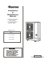
1
Installation
&
Maintenance
Manual
INVERTER-DRIVEN
MULTI-SPLIT
AIR CONDITIONER
(HEAT PUMP)
- Outdoor Units MODEL
AVW - 38UCSC
AVW - 48UCSC
AVW - 54UCSC
P00415Q
ORIGINAL INSTRUCTIONS
HISENSE
HISENSE
HISENSE
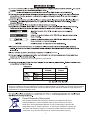
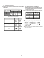
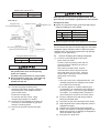
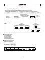
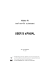
Install these air conditioners by local regulations or standards.
23WB
46 DB
30 DB
15.5 WB
15WB
-5 DB
15 DB
-20 WB
NOTE:
These air conditioners only are appliable of cooling or heating mode,do not operate cool and heat mode together,
if operate cool and heat mode at the same time,air conditioner system will be fluctuated for large difference in
temperature for changing operate mode.
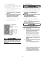
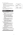
Correct Disposal of this product
This marking indicates that this product should not be disposed with other
household wastes. To prevent possible harm to the environment or human
health from uncontrolled waste disposal, recycle it responsibly to promote the
sustainable reuse of material resources. To return your used device, please use
the return and collection systems or contact the retailer where the product was
purchased. They can take this product for environmental safe recycling.
I
SAFETY SUMMARY
! Use refrigerant R410A in the refrigerant cycle. Do not charge oxygen, acetylene
or other flammable and poisonous gases into the refrigerant cycle when performing a
leakage test or an air-tight test. These types of gases are extremely dangerous and
can cause an explosion. It is recommended that compressed air, nitrogen or
refrigerant be used for these types of tests.
! Do not pour water into the indoor or outdoor unit. These products are equipped with
electrical parts. If poured, it will cause a serious electrical shock.
! Do not touch or adjust safety devices inside the indoor or outdoor units. If these
devices are touched or readjusted, it may cause a serious accident.
! Do not open the service cover or access panel for the indoor or outdoor units without
turning OFF the main power supply.
! Refrigerant leakage can cause difficulty with breathing due to insufficient air. Turn OFF
the main switch, extinguish any naked flames and contact your service contractor, if
refrigerant leakage occurs.
! The installer and system specialist shall secure safety against refrigerant leakage
according to local regulations or standards.
! Use an ELB (Electric Leakage Breaker). In the event of a fault, there is danger of an
electric shock or a fire if it is not used.
! Do not install the outdoor unit where there is a high level of oil mist, flammable gases,
salty air or harmful gases such as sulphur.
! Do not use any sprays such as insecticide, lacquer, hair spray or other flammable
gases within approximately one (1) meter from the system.
! If circuit breaker or fuse is often activated, stop the system and contact your service
contractor.
! Do not perform installation work, refrigerant piping work, drain piping and electrical
wiring connection without referring to our installation manual. If the instructions are
not followed, it may result in a water leakage, electric shock or a fire.
! Check that the ground wire is securely connected. If the unit is not correctly grounded,
it lead electric shock. Do not connect the ground wiring to gas piping, water piping,
lightning conductor or ground wiring for telephone.
! Connect a fuse of specified capacity.
! Do not put any foreign material on the unit or inside the unit.
! Make sure that the outdoor unit is not covered with snow or ice, before operation.
! Before performing any brazing work, check to ensure that there is no flammable
material around.
When using refrigerant be sure to wear leather gloves to prevent cold injuries.
! Protect the wires, electrical parts, etc. from rats or other small animals.
If not protected, rats may gnaw at unprotected parts and which may lead to a fire.
! Fix the cables securely. External forces on the terminals could lead to a fire.
II
SAFETY SUMMARY
! Do not install the indoor unit, outdoor unit, remote control switch and cable within
approximately 3 meters from strong electromagnetic wave radiators such as medical
equipment.
! Supply electrical power to the system to energize the oil heater for 12 hours before
start-up after a long shutdown.
! Do not step or put any material on the product.
! Provide a strong and correct foundation so that;
a. The outdoor unit is not on an incline.
b. Abnormal sound does not occur.
c. The outdoor unit will not fall down due to a strong wind or earthquake.
l The appliance is not to be used by children or person with reduced physical, sensory
or mental capabilities,or lack of experience and knowledge,unless they have been given
supervision or instruction concerning use of the appliance by a person responsible for
their safety.
l Children should be supervised they do not play with the appliance.
NOTE:
! It is recommended that the room be ventilated every 3 to 4 hours.
! The heating capacity of the heat pump unit is decreased according to the outdoor air
temperature. Therefore, it is recommended that auxiliary heating equipment be used in
the field when the unit is installed in a low temperature region.
l Operate the heat pump air conditioner within this range.
Regarding installation altitude below 1000 meters;
Regarding frequency of supply power within ±1% Hz of rated frequency.
Regarding transport storage temperature within -25~55℃.
CHECKING PRODUCT RECEIVED
! Upon receiving this product, inspect it for any shipping damage.
Claims for damage, either apparent or concealed, should be filed immediately with the shipping
company.
! Check the model number, electrical characteristics (power supply, voltage and frequency) and
accessories to determine if they are correct.
! The standard utilization of the unit shall be explained in these instructions.
! Therefore, the utilization of the unit other than those indicated in these instructions is not
recommended.
! Please contact your local agent, as the occasion arises.
! HISENSE ,s liability shall not cover defects arising from the alteration performed by a customer
,
without HISENSE s consent in a written form.
III
TABLE OF CONTENTS
1. Safety Summary ....................................................................................................................... 1
2. Structure ...................................................................................................................................1
2.1 Outdoor Unit & Refrigerant Cycle .....................................................................................1
2.2
Necessary Tools and Instrument List for Installation ........................................................3
3. Transportation and Handling ................................................................................................ ....4
3.1
3.2
Indoor Unit &Outdoor Unit Matching...................................................................................... 4
Transportation ..................................................................................................................4
4. Outdoor Unit Installation ............................................................................................................5
4.1
4.2
Factory-Supplied Accessories ......................................................................................... 5
Initial Check .....................................................................................................................5
4.4
Installation Work ..............................................................................................................6
4.3
Service Space .................................................................................................................6
5. Refrigerant Piping Work ...........................................................................................................8
5.1 Piping Materials ................................................................................................................8
5.2
5.3
Refrigerant Piping Work ...................................................................................................9
Branch Pipe ..................................................................................................................... 12
5.5
Air Tight Test.....................................................................................................................14
5.4
5.6
5.7
5.8
5.9
Piping Connection ........................................................................................................... 13
Vacuum Pumping and Charging Refrigerant....................................................................15
Caution of the Pressure by Check Joint ...........................................................................17
Fill the charge Refrigerant Register List............................................................................18
Collecting Refrigerant .......................................................................................................19
6. Electrical Wiring .........................................................................................................................19
6.1 General Check ................................................................................................................19
6.2
Electrical Wiring Connection ........................................................................................... 20
7. Outdoor Unit Dip-Switch Setting................................................................................................ 23
8. Test Run.................................................................................................................................... 24
9. Safety and Control Device Setting............................................................................................28
IV
1. Safety Summary
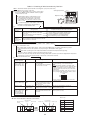
Table 1.1 Line-Up of Outdoor Unit
Capacity(KBtu/h)
Model
38
AVW-38UCSC
48
54
AVW-48UCSC
AVW-54UCSC
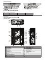
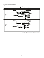
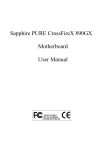
2. Structure
.
1
2
3
4
5
6
7
8
9
10
11
12
13
.
Compressor
Heat Exchanger
Propeller Fan
Fan Motor
Check Valve
Reversing Valve
Distributor
Check Joint for High/Low Pressure(Cool/Heat)
Strainer
Electrical Expansion Valve
Gas & Liquid Separator
Stop Valve for Gas Line
Stop Valve for Liquid Line
14
15
16
17
18
19
20
21
22
23
24
25
26
1
Bypass Solenoid Valve
High Pressure Switch
Pressure Sensor
Crankcase Heater
Electrical Box
Base assembly
Vibration Absorbing Rubber
Air Inlet
Outdoor Unit
Air Temperature Sensor
Condensator Temperature
Sensor
Liquid Line Refrigerant
Piping Connection
Gas Line Refrigerant
Piping Connection
Discharge Temperature
Sensor
Refrigerant Flow Direction(Cooling Operation)
Refrigerant Flow Direction(Heating Operation)
Field Refrigerant Piping
Flare Connection
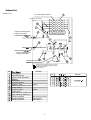
NO.
Remark
Compressor
Heat Exchanger
Gas & Liquid Separator
Strainer
Distributor
Reversing Valve
Capilary Tube
Electrical Expansion Valve
Reversing
Valve
Check Valve
Capilary
SolenoidTube
Valve
Check Joint
Stop Valve for Liquid Line
Individual
Valve
Stop Valve
for Gas Line
Pressure Switch
Pressure
Sensor
Check Joint
Pressure Sensor
NO.
Bypass
Bypass
Bypass
High Pressure Protect
High Pressure
Low Pressure
2
Material
2.2
No.
1
Necessary Tools and Instrument List for Installation
Tool
Tool
6
Copper Pipe Bender
7
3
Phillips
Screwdriver
Vacuum Pump
4
Refrigerant Gas
Hose
Megohmmeter
2
5
Handsaw
No.
No.
Tool
No.
16
Leveller
Tool
11
Spanner
Manual Water Pump
12
Charging Cylinder
17
8
Pipe Cutter
13
Gauge Manifold
18
9
Brazing Kit
14
Cutter for Wires
19
Ammeter
10
Hexagon Wrench
15
Gas Leak Detector
20
Voltage Meter
Clamper for Solderless Terminals
Hoist
(for Indoor Unit)
Use tools and measuring instruments only for the new refrigerant which is directly touch to refrigerant.
": Interchangeability is available with current R22
#: Prohibited
Measuring Instrument and Tool
Pipe Cutter
Chamfering Reamer
Flaring Tool
Refrigerant
Pipe
"
"
" !
"
Extrusion
Adjustment Gauge
!
-
Pipe Bender
"
"
"
"
Expanding Tool
!
"
"
"
Brazing Tool
"
"
Nitrogen Gas
"
"
Lubrication Oil
(for Flare Surface)
!
$
Refrigerant
Cylinder
!
$
"
"
!
$
Manifold Valve
!
$
Charging Hose
!
$
Charging Cylinder
#
#
Weight Scale
"
"
!
$
Torque Wrench
Vacuum Pump
Adapter for
Vacuum Pump
Vacuum
Drying
.
Refrigerant
Charge
Interchangeability
with R22
R410A R407C
Refrigerant Gas
Leakage Detector
&
&
!: only for Refrigerant R410A (No Interchangeability with R22)
$: only for Refrigerant R407C (No Interchangeability with R22)
Reason of Non-Interchangeability and Attention
(%: Strictly Required)
-
* The flaring tools for R407C are applicable to R22.
* If using flaring tube, make dimension of tube
larger for R410A.
* In case of material 1/2H, flaring is not available.
* In case of material 1/2H, bending is not available.
Use elbow for bend and braze.
* In case of material 1/2H, expanding of tube is not
available. Use socket for connecting tube.
* For !12.7, !15.88, spanner size is up 2mm.
* For !6.35, !9.53, !19.05, spanner size is
the same.
* Perform correct brazing work.
* Strict Control against Contamin
(Blow nitrogen during brazing.)
* Use a synthetic oil which is equivalent to the oil
used in the refrigeration cycle.
* Synthetic oil absorbs moisture quickly.
* Check refrigerant cylinder color.
% Liquid refrigerant charging is required regarding
zeotoropic refrigerant.
% The current ones are applicable. However, it is
required to mount a vacuum pump adapter which
can prevent from reverse flow when a vacuum
pump stops, resulting in no reverse oil flow.
* No interchangeability is available due to higher
pressures when compared with R22.
% Do not use current ones to the different refrigerant.
If used, mineral oil will flow into the cycle and cause
sludges, resulting in clogging or compressor failure.
Connection diameter is different; R410A: UNF1/2,
R407C: UNF7/16.
* Use the weight scale.
* The current gas leakage detector (R22) is not
applicable due to different detecting method.
&: Interchangeability with R407C.
3
Use
Cutting Pipe
Removing Burrs
Flaring for Tubes
Dimensional Control
for Extruded Portion
of Tube after Flaring
Bending
Expanding Tubes
Connection of
Flare Nut
Brazing for Tubes
Prevention from
Oxidation during
Brazing
Applying Oil to the
Flared Surface
Refrigerant Charging
Vacuum Pumping
Vacuum Pumping,
Vacuum Holding,
Refrigerant Charging
and Check of
Pressures
Measuring
Instrument for
Refrigerant Charging
Gas Leakage Check
3. Transportation and Handling
3.1 Indoor Unit&Outdoor Unit Matching
Below Indoor Unit matching Hi Smart L outdoor unit.
Table 3.1 Indoor Unit Model
Indoor Unit
Rated Capacity (KBtu/h)
07
09
12
14
17
18
22
24
Ceiling Ducted Type
High Static Pressure
Ceiling Ducted Type
Low Static Pressure
Low-height
Ceiling Ducted Type
Slim Ceiling Ducted
Type
Fig. 3.1 Hanging Work for Transportation
4-Way Cassette
Type
Wall-Mounted Type
Allow
Indoor Unit total Capacity must be 50% to 130% for
If have no package to move,Please protect with
cloth or paper
Outdoor Unit Rated Capacity
Table 3.2 System Matching
Outdoor Unit Model
Capacity(KBtu/h)
38
48
54
3.2
Put Cloth or Paper
Rated Capacity(KBtu/h)
Min. Matching Max. Matching Matching
Capacity
Capacity
Quantity
(KBtu/h)
(KBtu/h)
19
24
27
24
62
70
Min. Single
Operate Capacity
(KBtu/h)
to
to
to
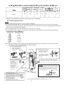
Transportation
Transport the product as close to the installation
location as practical before unpacking.
Fig.3.2 Transportation for no wooden base
Do not put any material on the product.
Apply two lifting wires onto the outdoor unit,
when lifting it by crane.
! Hanging Method
When hanging the unit, ensure a balance of
the unit, check safety and lift up smoothly.
Outdoor Unit Model
(KBtu/h)
Net Weight
38
93
95
97
48
54
(1) Do not remove any packing materials.
(2) Hang the unit under packing condition with
two (2) ropes, as shown in Fig. 3.1.
Do not put any foreign material into the
outdoor unit and check to ensure that none
exists in the outdoor unit before the
installation and test run. Otherwise, a fire or
failure, etc. may occur.
4
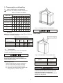
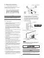
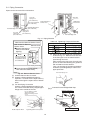
4. Outdoor Unit Installation
4.1
Direction of Strong Wind
Factory-Supplied Accessories
Check to ensure that the following accessories
are packed with the outdoor unit.
Table 4.1 Factory-Supplied Accessories
Accesso
Washer
Q'ty
4
Recommend
for Anchor Bolts
Direction of Air Discharge
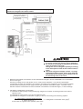
• In case of installation in the open spaces
unavoidably where there is no buildings or
surrounding structures, adopt the wind guard
set or install near the wall to avoid facing the
wind directly. Ensure that the service space
should be secured.
NOTE
If any of these accessories are not packed with
the unit, please contact your contractor.
4.2
(1) Using Wind Guard
Initial Check
Wind Guard Set
(Optional)
• Install the outdoor unit where good ventilation is
available, and where it is dry.
• Install the outdoor unit where the sound or the
discharge air from the outdoor unit does not
affect neighbors or surrounding vegetation.
The operating sound at the rear or right/left
sides is higher than the value in the catalog at
the front side.
• Check to ensure that the foundation is flat, level
and sufficiently strong.
• Do not install the outdoor unit where there is a
high level of oil mist, salty air or harmful gases
such as sulphur.
• Do not install the outdoor unit where the
electromagnetic wave is directly radiated to the
electrical box.
• Install the outdoor unit as far as practical, being
at least 3 meters from the electromagnetic
wave radiator.
• When installing the outdoor unit in snowcovered areas, mount the field-supplied hoods
at the discharge side of the outdoor unit and
the inlet side of the heat exchanger.
• Install the outdoor unit where it is in the shade
or it will not be exposed to direct sunshine or
direct radiation from high temperature heat
source.
• Do not install the outdoor unit where dust or
other contamination could block the outdoor
heat exchanger.
• Install the outdoor unit in a space with limited
access to general public.
Model
Quantity
HWSP-160A
Strong Wind
(2) A Wall to Guard Against Wind
Wall
Secure the adequate
service space(600mm).
Direction of Strong Wind
NOTE:
If the extreme strong wind blows directly against
the air discharge portion, the fan may rotate
reversely and be damaged.
Aluminum fins have very sharp edges. Pay
attention to the fins to avoid any injury.
NOTE
• Do not install the outdoor unit in a space where
a seasonal wind directly blows to the outdoor
heat exchanger or a wind from a building space
directly blows to the outdoor fan.
Install the outdoor unit on a roof or in an area
where people except service engineers can not
touch the outdoor unit.
5
1
4.3
Service Space
Install the outdoor unit with a sufficient space around the outdoor unit for operation and maintenance as
shown below Fig4.1.
Upper Side is Open
Left Right&Upper Side is Open
'
0
00
>
20
>2
0
>30
>5
Multiple Installation
Single Installation
Single Installation
0
>100
>30
>100
Keep a distance of 100mm between
>5 at least
right side
0
0
Keep a distance of 100mm between
right side at least
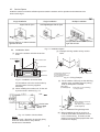
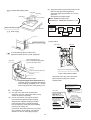
4.4
Fig. 4.1 Installation Space
Installation Work
(3) Example of fixing outdoor unit by anchor
bolts.
(1) Secure the outdoor unit with the anchor
bolts.
Max. 21mm
(After cut "A " )
Air Flow Direction
Base of Outdoor Unit
A
Nut
Special Washer
Anchor Bolt
Max.
21mm
M10
Cut this portion when this type
of anchor bolt is used.
If not, it is difficult to remove
the service cover.
Concrete
Filled Mortar
(4) Fix the outdoor unit firmly so that declining,
making noise, and falling down by strong
wind or earthquake is avoided.
Fix the outdoor unit to the anchor bolts by
special washer of factory-supplied
accessory.
(2) When installing the outdoor unit, fix the unit
by anchor bolts. Refer to Fig. 4.3
regarding the location of fixing holes.
Unit
Air Outlet
Anchor Bolt
Fig. 4.4 Fixing Example
Fig. 4.2 Installation of Anchor Bolts
Front
Concrete
Fixing Plate
(Field-Supplied)
Both sides on the unit fixing
can be possible.
When vibration measures
are necessary,
add vibration proof rubber.
(Field-Supplied)
Anchor bolts
hole
Fig. 4.5 Additional Fixing Arrangement
(5) When installing the unit on a roof or a
veranda, drain water sometimes turns to
ice in a cold morning. Therefore, avoid
draining in an area where people often use
because it is slippery.
Fig. 4.3 Position of Anchor Bolts
NOTE:
When the mark * dimension is secured, piping
work from bottom side is easy without
interference of foundation.
6
Recommended Metal Plate Size (Field-Supplied)
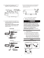
(6) In case of the drain piping is necessary for
the outdoor unit, use the drain-kit
(HDBS-26 or HDBS-26L:Optional Parts) .
Material: Hot-Rolled Mild Steel Plate (SPHC)
Plate Thickness: 4.5T
C10
Drain Hole
Drain Hole
Hole
Position of Drain pipe joint
Optional
Front(Air Outlet)
Fig. 4.6 Frame and Base Installation
5.
(7) The whole of the base of the outdoor unit
should be installed on a foundation. When
using vibration-proof mat, it should also be
positioned the same way.
When installing the outdoor unit on a fieldsupplied frame, use metal plates to adjust
the frame width for stable installation as
shown in Fig. 4.6.
Use refrigerant R410A in the refrigerant cycle.
Do not charge oxygen, acetylene or other
flammable and poisonous gases into the
refrigerant cycle when performing a leakage
test or an air-tight test. These types of gases
are extremely dangerous and can cause an
explosion. It is recommended that
compressed air, nitrogen or refrigerant be
used for these types of tests.
Incorrect
5.1
Base Width of Outdoor Unit
75mm
Piping Materials
(1) Prepare locally-supplied copper pipes.
(2) Select the piping size from the Table 5.1.
(3) Select clean copper pipes. Make sure
there is no dust and moisture inside of the
pipes. Blow the inside of the pipes with
nitrogen or dry air, to remove any dust or
foreign materials before connecting pipes.
Outdoor Unit
is Unstable.
Frame
Frame Width 60mm
(Field-Supplied)
NOTE
! Cautions for Refrigerant Pipe Ends
Correct
Base Width of Outdoor Unit
75mm
When installing pipe through
the wall, secure a cap at the
end of the pipe.
Incorrect
Correct
Outdoor Unit
is Stable.
Frame
Refrigerant Piping Work
Hole
Metal Plate
Correct
Incorrect
Rain water can
enter.
Attach a cap
or vinyl bag with
rubber band.
7
Correct
Incorrect
Hole
Attach a cap
or vinyl tape.
Metal Plate
100mm or more
Do not place the pipe
directly on the ground.
Attach a cap
or vinyl tape.
! Cap the end of the pipe when the pipe is to
be inserted through a hole.
! Do not put pipes on the ground directly
without a cap or vinyl tape at the end of the
pipe.
! Flaring Dimension
Perform the flaring work as shown below.
Diameter
! Piping Thickness and Material
Use the pipe as below.
Diameter
Thickness
Material
Material is based on a JIS standard (JIS B8607).
! Flare Nut Dimension
Use the flare nut as below.
<Flare Nut Dimension B (mm)
Diameter
R410A
Flare Nut
Dimension is based on a JIS standard
(JIS B8607).
8
5.2
Refrigerant Piping Work
(1) Ensure that the directions for refrigerant piping work according
to the tables.
Table 5.1 Limitation of Outdoor Unit
Capacity
(KBtu/h)
Diameter
Outer Diameter of Pipe
Gas
Liquid
(2) Additional Refrigerant Charge R410A
Although refrigerant has been charged into this unit,
it is required that additional refrigerant be charged
according to piping length.
Table 5.3
is Outdoor Unit Ref.charge before shipment
Branch Pipe
Outdoor Unit Model
38
Capacity(KBtu/h)
HFQ-052F
48
54
Table 5.2 Indoor Unit Pipe Model
Indoor Unit Pipe Model
38
3.8
48
3.8
54
4.1
Gas Pipe Liquid Pipe
Calculate charge refrigerant quantity by liquid pipe
length,charge it to refrigerant cycle.
07~14
liquid length
0.04
liquid length
17~18
Inform local service the quantity of charging refrigerant
after finish charging.
22~24
9
Table 5.4 Refrigerant Pipe System&Additional Refrigerant Quantity
System
Item
Example
One outdoor unit joint six indoor units,
pipe materials are acquired from local
Branch pipe for Line Branch
Outdoor Unit
Oil Trap is recommended
at every 10meters lift
Max.Saving Length Lt
Max.Pipe Length
Total Pipe Lentth
Outdoor is Higher than
High Distance
Indoor Unit
between Outdoor
Indoor is Higher than
and Indoor Unit
Outdoor Unit
Max.High Distance betwen Indoor and
Indoor or Indoor and Branch Pipe
Max.Pipe Length From "a" Branch Pipe to
between Branch Indoor of Max. Distance
Pipe and Indoor From every Branch Pipe
to Indoor of connecting
Choose Branch
Pipe(KBtu/h)
with HFQ-052F
38~54
<Example>
AVW-54UCSC
Total refrigerant charge
of this system is calculted
in the following formula.
Symbol
Liquid
Pipe
thereinto
Model
Length
Total Liquid
Length
Total Liquid
Length
Total
10
3 Branch Pipe for Line Branch
Table
Branch Pipe
5
T Shape Branch Pipe
H FQ - 052F
Unit
11
Inner Diameter
Outer Diameter
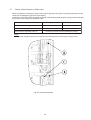
5.4 Piping Connection
Pipes can be connected from 4 directions.
Stop Valve
Rear Side
Piping Cover
Right Side
Piping Work
(Knock-Out
Hole)
Rear Side Piping Work
(Knock-Out Hole)
Remove Direction of
Service Cover
Distribut Pipe
Right Side Piping Work
(Knock-Out Hole)
Front Side Piping Cover
Bottom Side
Piping Work
Front Side
(Knock-Out Hole)
Piping Work
(Knock-Out Hole)
Front Side Piping Cover
Fig. 5.1 Piping Direction
Table 5.6 Tightening Torque for Flare Nut
Pipe Size
Torque
Note Item for Remove Service Cover
Main Points for Remove
Service Cover
Service Cover
Remove the bolts of
service cover follow
right Fig.
(4) Pipes can be connected from 4 directions
as shown Fig. 5.1. Make a knock-out hole
in the front pipe cover or bottom base to
pass through the hole.
After removing the pipe cover from the unit,
punch out the holes following the guide line
with screwdriver and a hammer.
Then, cut the edge of the holes and attach
insulation (Field-Supplied) for cables and
pipes protection.
Note
Press the service cover
when remove the bolts.
It is possible for service
cover to slide down.
Fix Hook (3 Points)
Press the service cover at front,
then remove it down slowly.
Front Side Piping Cover
Fig. 5.2 Remove Service Cover
(1) Confirm that the valve is closed.
(2) Prepare a field-supplied bend pipe for
liquid line. Connect it to the liquid valve by
flare nut through the square hole of bottom
base.
(3) For Gas Piping Connection
Prepare a field-supplied bend pipe for gas
line. Braze it and the factory-supplied pipe
flange at the outside of the unit.
Gap
Connect Front and Right Side Pipe
Right Side Piping Hole
Do not apply the double
spanner work here.
Refrigerant leakage shall
occur.
B
A
Double Spanner Work
Front Side Piping Hole
Tightening Work for Stop Valve
12
Bottom Side Piping Work
Power Wire
Gas Piping
Liquid Piping
Liquid Piping
Knock Out Hole
(3) Apply the oil thinly at the seat surface of the
flare nut and pipe before tightening.
And when tightening the flare nut, use two
spanners.
Refrigerant Oil is field-supply.
Model: α68HES-H (Ether Oil)
Manufacturer: IDEMITSU KOSAN Co., Ltd.
Procedure
Completion
of Ref.
Piping
Bottom Side Piping Hole
Bottom Base
Rear Piping Work
c
Applying
Nitrogen
Gas
Check of
Pressure
Decrease
Pass
Repairing
of Leakage
Part
Rear Cover
(4) Stop Valve
Rear Piping Guide Hole
Gas Valve
Liquid Valve
To avoid damage protect cables and
pipes with rubber sheath (Field- Supplied).
Rubber Sheath(attatch part)
Pipe Cover
Cut a "+" shape gap at rubber sheath
center,wire lead rubber sheath.
Gas Pipe
Stop Valve Core for Opening and closing
Power and Communication Wire
Liquid Pipe
5.5
Fig.5.3 Stop Valve Position
Heat Preservation Pipe
To prevent gaps use a rubber bush and
insulation (Factory-Supplied) adequately
when installing the piping cover. Cut the
lower side guide line of the piping cover
when attaching work is difficult.
Air Tight Test
Operation of the stop valve should be
performed according to the below.
<Liquid Valve>
Do not apply two spanners
at this posotion.If applied,
leakage will occur
Check Joint
Only the charging hose
can be connected
Tighten the cap with a
torque below.
Liquid Valve:16N. m Cap
Tighten the cap with a
torque below.
(Attach this after work)
Gas Valve:49N .m
Liquid Valve:37N. m
O-Ring
(rubber)
Refrigerant Piping
Hexagonal
Wrench(Size:4mm)
To open or close
spindle valve
(1) The stop valve has been closed before
shipment, however, make sure that the stop
valves are closed completely.
(2) Connect the indoor unit and the outdoor
unit with field-supplied refrigerant piping.
Suspend the refrigerant piping at certain
points and prevent the refrigerant piping
from touching the weak part of the building
such as wall, ceiling, etc.
(If touched, abnormal sound may occur due
to the vibration of the piping. Pay special
attention in case of short piping length.)
(
(
13
)
)
Use two spanners
here to squeeze
flare nut
Spindle Valve
Counterclockwise
. . .. Open
Clockise . . .. Close
Close before shipment
Ref.Pressure
Refrigerant Piping
Liquid Stop Valve
.
Spindle Valve Torque (N m)
Gas
Liquid
4
After pipe and nut cap connected,when make air test ,
open the stop valve spindle cap,make sure valve closed
<Gas Valve>
Hexagonal Wrench
(to open/close spindle valve)
already(clock wise).
Cap
Refrigerant Pressure
Tighten the cap with a torque
29.4N.M
! Tighten nut cap below torque,great torque will bring on
refrigerant leakage of valve spindle.
Pipe Diameter
Spindle Valve
Counterclockwise---- Open
Clockwise----Close
(Closed before Shipment)
! Make air tighten test after valve spindle turn off closely.
O Ring
(Rubber)
Check joint
(Only charging hose can be connected)
Tighten the cap with a torque 9N.M
Note:
Do not connect nut cap on test joint,supply for connecting
refrigerant charge soft pipe. It have no effect for system
capacity when connect jonit cap and valce cap opened
together "pu chi" light sound.
Refrigerant Piping
5.6
Hexagonal Wrench Size (mm)
Gas
Tighten Torque
Vacuum Pumping and charge refrigerant
(1) Connect a mani-fold gauge to the check
joints at the both sides.
Continue vacuum pumping work until the
pressure reaches 756mmHg or lower for
one to two hours.
After vacuum pumping work, stop the
mani-fold valve’s valve, stop the vacuum
pump and leave it for one hour. Check to
ensure that the pressure in the mani-fold
gauge does not increase.
Liquid
! Do not apply an abnormal big force to
the spindle valve at the end of opening
(5.0N. m or smaller).
The back seat construction is not provided.
! Do not loosen the stop ring. If the stop ring
is loosened, it is dangerous, since the
spindle will hop out.
Note:
1. This unit is only for the refrigerant R410A. The
manifold gauge and the charging hose should
be exclusive use for R410A.
2. If vacuum degree of -0.1MPa (756mmHg) is
not available, it is considered of gas leakage or
entering moisture. Check for any gas leakage
once again. If no leakage exists, operate the
vacuum pump for more than one to two hours.
(2) Connect adjusted valve and charge kettle to
check joint of liquid valve.
(3) Fully open the gas valve and liquid valve slowly.
(5) Connect the gauge manifold using
charging hoses with a nitrogen cylinder to
the check joints of the liquid line and the
gas line stop valves.
Perform the air-tight test.
Do not open the stop valves. Apply
nitrogen gas pressure of 4.15MPa.
(6) Check for any gas leakage at the flare nut
connections, or brazed parts by gas leak
detector or foaming agent.
(7) After the air tight test, release nitorogen
gas.
(4) Open adjusted valve to add refrigerant (must be
refrigerant is liquid).
(5) Operate cool mode,charge stated refrigerant.
(6) Confirm the capacity of charging refrigerant with
balance.an excess or a shortage of refrigerant is
cause of trouble to the units.
(7) Fully open the liquid valve.
14
Never use the refrigerant charged in the outdoor unit for air purging.
Insufficient refrigerant will lead to failure.
Thermal Insulation Finishing Work
Wind tape from outside of
thermal insulating of gas piping
and liquid piping
Indoor Unit
Cover the flare nut and union of the
piping connection with thermal insulation.
Gas Line
Liquid Line
Cover the liquid line
with thermal insulation.
Liquid Line Stop Valve
Gas Line Stop Valve
Insulate the liquid pipe for
prevention of the capacity
decrease according to the
ambient air conditions and
the dewing on the pipe surface
by the low pressure.
Check to ensure that there is
no gas leakage. When large
amount of the refrigerant leaks,
the troubles as follows may occur;
1. Oxygen Deficiency
2. Generation of Harmful Gas
Due to Chemical Reaction
with Fire.
Nitrogen Tank
for Air Tight Test
and
Nitrogen Blow
during Brazing
Manifold
Gauge
Vacuum Pump
! At the test run, fully open the spindle.
If not fully opened, the devices will be damaged.
! An excess or a shortage of refrigerant is the main
cause of trouble to the units.
Charge the correct refrigerant quantity according
to the description of label at the inside of service
cover.
! Check for refrigerant leakage in detail. If a large
refrigerant leakage occurs, it will cause difficulty
with breathing or harmful gases would occur if a
fire was being used in the room.
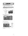
1. Maximum Permissible Concentration of HFC GAS R410A charged in the DC INVERTER is an incombustible
and non-toxic gas.
However, if leakage occurs and gas fills a room, it may cause suffocation. The maximum permissible
concentration of HCFC gas, R410A in air is 0.3kg/m3, according to the refrigeration and air conditioning facility
standard (KHK S 0010) by the KHK (High Pressure Gas Protection Association) Japan. Therefore, some
effective measure must be taken to lower the R410A concentration in air below 0.3kg/m3, in case of leakage.
2. Calculation of Refrigerant Concentration
(1) Calculate the total quantity of refrigerant R (kg) charged in the system connecting all the indoor units of
objective rooms.
(2) Calculate the room volume V (m3) of each objective room.
(3) Calculate the refrigerant concentration C (kg/m3) of the room according to the following equation.
R: Total Quantity of Charged Refrigerant (kg)
= C: Refrigerant Concentration ! 0.3 (kg/m3)
V: Room Volume (m3)
If local codes or regulations are specified, follow them.
15
5.7
Caution of the Pressure by Check Joint
When the pressure is measured, use the check joint of gas stop valve ((A) in the figure below) and use the
check joint of liquid piping ((B) in the figure below).
At that time, connect the pressure gauge according to the following table because of high pressure side and
low pressure side changes by operation mode.
Cooling Operation
Heating Operation
Check Joint for Gas Stop Valve "A"
Low Pressure
High Pressure
Check Joint for Piping "B"
High Pressure
Low Pressure
Check Joint for Liquid Stop Valve "C"
Exclusive for Vacuum Pump and Refrigerant Charge
NOTE:
Be careful that refrigerant and oil do not splash to the electrical parts at removing the charge hoses.
Fig 5.4 Check Joint Position
16
5.8
Additional Refrigerant Charge
It is necessary additional refrigerant charge as follows.
Additional Refrigerant Charge Calculation
Although refrigerant has been charged into this unit, it is required that additional refrigerant be charged according
to piping length.
A. Determine an additional refrigerant quantity according to the following procedure, and charge it into the system.
B. Record the additional refrigerant quantity to facilitate service activities thereafter.
1. Calculating Method of Additional Refrigerant Charge (W kg)
<EXAMPLE>
RAS-5FSVN1(Q)
AVW-54UCSC
<Table 1>
W0:
Outdoor Unit
Outdoor Unit
Capacity(KBtu/h) Ref.Charge
See Example for Model AVW-54UCSC, and fill in the following table.
Pipe Diameter (mm)
Total Piping Length (m)
Additional Charge (kg)
W11=
W12=
38
3.8
48
3.8
54
4.1
NOTE:
W0 is outdoor unit ref. charge before shipment.
0.50
Total Piping Length
Additional Charge
Pipe Diameter (mm)
Total Piping Length (m)
Additional Charge (kg)
W11=
W12=
Total Piping Length
Total Ref.Charge
2. Charging Work
Charge refrigerant (R410A) into the system as follows.
(1) For charging refrigerant, connect the gauge mani-fold using charging hoses with a refrigerant cylinder to the check joint
of the liquid line stop valve.
(2) Fully open the gas line stop valve and slightly open the liquid line stop valve.
Charge refrigerant by opening the gauge manifold valve.
(3) Charge the required refrigerant by operating the system in cooling.
Ensure to charge correct volume by utilizing a weight scale. An excess or shortage of refrigerant is the main cause
of trouble to the units.
Fully open the liquid line stop valve after completing refrigerant charge.
3. Record of Additional Charge
Record the refrigerant charging quantity in order to facilitate maintenance
and servicing activities.
Total refrigerant charge of this system is calculated in the following formula.
Total Ref. Charge of This System = W + W 0
This System
=
+
=
kg
Total Additional Charge W
kg
Total Ref. Charge of This System
kg
Date of Ref. Charge Work
Day
Month
Year
4. Dip-Switch Setting for Piping Length
Follow below ,setting the Dip-Switch for piping length.
5. Notice of Additional Charge
(1) The additional refrigerant need to be reduced 150g
for each 12/14 slim ceiling ducted type indoor unit.
(2) The additional refrigerant need to be added if the
matched indoor unit and outdoor unit is between
100% ~130% .The additional refrigerant is 150g for
each 10% which is over 100% .
(3) The total refrigerant of the unit must be less
than 7.9 kg.
Mark
Shipment
17
Show Switch Key Position)
O.U.is located
I.U.is located
higher than O.U.20m higher than I.U. 25m
5.9
6.
Collecting Refrigerant
When the refrigerant should be collected into the
outdoor unit due to indoor/outdoor unit relocation,
collect the refrigerant as follows.
(1) Attach the manifold gauge to the gas stop
valve and the liquid stop valve.
(2) Turn ON the power source.
(3) Set the DSW1-1 pin of the outdoor unit
PCB at the “ON” side for cooling operation.
Close the liquid stop valve and collect the
refrigerant.
(4) When the pressure at lower pressure side
(gas stop valve) indicates -0.01MPa
(684mmHg), perform the following
procedures immediately.
* Close the gas stop valve.
* Set the DSW1-1 pin at the “OFF” side.
(To stop the unit operation.)
(5) Turn OFF the power source.
Electrical Wiring
! Turn OFF the main power switch to the
indoor unit and the outdoor unit and wait for
more than 1 minute before electrical wiring
work or a periodical check is performed.
! Check to ensure that the indoor fan and the
outdoor fan have stopped before electrical
wiring work or a periodical check is
performed.
! Protect the wires, electrical parts, etc. from
rats or other small animals.
If not protected, rats may gnaw at
unprotected parts and at the worst, a fire
will occur.
! Avoid the wirings from touching the
refrigerant pipes, plate edges and electrical
parts inside the unit.
If not do, the wires will be damaged and at
the worst, a fire will occur.
Dip Switch
(DSW1-ON)
Liquid
! Tightly secure the power source wiring
using the cord clamp inside the unit.
Manifold Gauge
6.1
Stop Valve
General Check
(1) Make sure that the field-selected electrical
components (main power switches, circuit
breakers, wires, conduit connectors and
wire terminals) have been properly
selected according to the electrical data.
Make sure that the components comply
with National Electrical Code (NEC).
(2) Check to ensure that the voltage of power
supply is within +10% of nominal voltage
and earth phase is contained in the power
supply wires. If not, electrical parts will be
damaged.
(3) Check to ensure that the capacity of power
supply is enough.
If not, the compressor will be not able to
operate cause of voltage drop abnormally
at starting.
(4) Check to ensure that the earth wire is
connected.
(5) Check to ensure that the electrical
resistance is more than 1 megohm, by
measuring the resistance between ground
and the terminal of the electrical parts.
If not, do not operate the system until the
electrical leakage is found and repaired.
Gas Stop Valve
Measure the low pressure by the pressure gauge
and keep it not to decrease than -0.01MPa. If the
pressure is lower than -0.01MPa, the compressor
may be faulty.
18
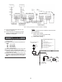
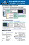
6.2
(2) Connect the wires between the outdoor
and indoor units to terminals 1 and 2 on the
terminal board.
If power supply wiring is connected to 1
and 2 of terminal board (TB1), printed
circuit board will be damaged.
Refer to Fig. 6.1.
Electrical Wiring Connection
(1) Connect the power supply wires to the
terminal board in the electrical control box
of both outdoor unit and indoor unit. And
connect the earth wire to the electrical
control box of outdoor unit.
In addition, connect the earth wire to earth
screw in the electrical control box of indoor
unit. Refer to Fig. 6.2.
CORRECT (ONE PHASE)
Remote
Control
Switch
(Option)
1P,220-240V~ 50Hz
1P,220-240V~ 50Hz
ELB for
Outdoor Unit
FUSE
ELB for
Indoor Unit
Outdoor Unit
Indoor Unit
Switch
INCORRECT (ONE PHASE)
Remote
Control
Switch
(Option)
1P,220-240V~ 50Hz
ELB for
Outdoor Unit
FUSE
Indoor Unit
Outdoor Unit
Switch
Fig. 6.1 One phase indoor unit and outdoor unit
communication wire connection
Do not connect the Power Source Line to the terminal 1 and 2.
These terminals are for the Control.
If connected, the printed circuit board will be damaged.
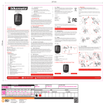
NOTES:
1. In case of total wiring length at intermediate
wiring between outdoor unit and indoor unit
and between indoor units is less than 100m, it
is possible to use the normal wiring (more than
0.75mm2) except twist pair cable.
2. Total wiring length for remote control switch
can be extended up to 500m.
If total wiring length less than 30m, it is
possible to use the normal wiring (0.3mm2)
except twist pair cable.
(3) Do not wire in front of the fixing screw of
the service panel. If do, the screw can not
be removed.
(4) Use twist pair cable with shielded for
control between outdoor unit and indoor
unit, control wiring between indoor units,
wiring (1 and 2) for remote control switch
and transmission wiring (A and B)
for remote control switch .
19
220-240V~ 50Hz
220-240V~ 50Hz
ELB
ELB
Remote
Control Switch
(Option)
Remote
Control Switch
(Option)
Switch
Switch
Outdoor Unit
No.1 Indoor Unit
Fuse
No.2 Indoor Unit
Fuse
Power Source Cable
Pay an attention to the phase
of power source when wiring.
Remote Control
Switch Cable
Control Communication Cable
2
Shielded Twist-Pair Cable 0.75mm x 2
This cable dose not need any polarity.
Do not apply an excessively high
voltage to this cable. (Rated Voltage: 5V)
2
Shielded Twist-Pair Cable 0.75mm x 2
This cable dose not need any polarity.
Do not apply an excessively high
voltage to this cable. (Rated Voltage: 12V)
Fig. 6.2 Wiring Connection for Indoor & Outdoor (1 PHASE)
(5) The recommended fuse sizes etc. are
shown in Table 6.1.
(6) In the case that a conduit tube for feildwiring not used,fix rubber bushes with
adhesive on the panel.
NOTE:
Supply the power source of outdoor units and indoor
units respectively.
(1) Power Source Wiring
Power source wiring is fundamentally
according to this method.
(1) Power Source Wiring
! Install an ELB in the power source.
If ELB is not used, it will cause electric shock or
fire at the worst.
! The tightening torque of each screw shall be as
follows.
M4: 1.0 to 1.3 N-m
M5: 2.0 to 2.5 N-m
M6: 4.0 to 5.0 N-m
M8: 9.0 to 11.0 N-m
M10: 18.0 to 23.0 N-m
Keep the above tightening torque when wiring work.
1
ELB (Earth Leakage Breaker)
2
FUSE
3
S (Main Switch)
4
Power Source Wiring (O.U.)
5
Earth Wiring (O.U.)
1 ELB
6
Transmission Wiring (O.U. ~ I.U.)
2 FUSE
7
Power Source Wiring (I.U.)
8
Earth Wiring (I.U.)
Outdoor Unit Power Source
220-240V~ 50Hz
3 S
4
! Install main switch and ELB for each system
separately. Select the high response type ELB that
is acted within 0.1 second.
! Separate the control wiring between outdoor unit
and indoor unit more than approximately 5 to 6cm
from power supply wiring. Do not use a coaxial
cable.
Indoor Unit Side
Outdoor
Unit
5
6
S
FUSE
ELB
Indoor Unit
Power Source
220-240V~ 50Hz
20
7
7
Indoor
Unit
7
Indoor
Unit
8
6
8
6
Power Source Transmitting
Cable Size
Cable Size
Earth
Wire
Size
Fuse
EN60335-1 *1 EN60335-1 *1
(mm )
(mm )
(mm )
0.75
6.0
28
38~54
6.0
40
30
40
*1 Refer to the NOTES for selection of the power source cable size.
NOTES:
1) Follow local codes and regulations when selecting field wires.
2) The wire sizes marked with *1 in the above table are selected at the maximum current of the unit according to
the European Standard, EN60335-1.Use the wires which are not lighter than the ordinary polychloroprene sheathed
flexible cord (code designation H05RN-F).
3) Use a shielded cable for the transmitting circuit and connect it to ground.
4) In the case that power cables are connected in series, add each unit maximum current and select wires below.
Selection According to EN60335-1
Current i (A)
Wire Size (mm )
3
1.0~2.5
3
6
1.0~2.5
6
10
1.0~2.5
16
10
1.5~4.0
16
2.5~6.0
25
4.0~10.0
25
32
50
6.0~16.0
32
50
63
10.0~25.0
63
*2
5) Run through the cables using conduit tube,and Completely seal the end of conduit tube with sealing materials.
*2 : In the case that current exceeds 63A,Don't series connection
Keep a distance between
each wiring terminal and
attach insulation tape or
sleeve as shown in the figure.
Correct
Rear Cover
Incorrect
Wiring Method with Clamp
1. Insert the wires by into the
cord clamp and clamp them
as shown in the figure.
2. Perform wiring so that wires
do not touch the compressor,
refrigerant pipes or edge of
the covers.
Insulation Tape or Sleeve
Do not use a solderless
terminal when
a single wire is used.
If used it causes
abnormal heating at
the caulking portion
of the terminal.
If a single wire is used
connect the
wire direct as shown
in the figure.
Earth
Wire
Make a loop of the wires so that disconnecting
the wirings for replacing parts is not required.
CAUTION:
When using conduit, do NOT lead it in the outdoor
unit. If the conduit wiring touches the compressor
and refrigerant cycle in the outdoor unit, it may
cause to damage them.
Power Supply
Cable
Piping Cover
Earth Wire
Control Cable
Rubber Bush
(Accessory)
Conduit
Power Supply Cable
Fig. 6.3 Wiring Connection of Outdoor Unit
21
Install a multi-pole main switch with a space of 3.5mm or more between each phase.
7.
Outdoor Unit Dip-Swtich Setting
Turn off all power switch before setting Dip-Switch,else Dip-Switch is of no effect.
Follow this table setting Dip-Switch,
symbol denote the position of Dip-Switch contact joint.
ALL OFF:Shipment Set
Ref. Cycle No.
Setting
Communication
Setting
Optional Function Setting
Input Power
Setting Setting
Input Power
ALL OFF:Shipment
Set
ALL OFF: Shipment
Set
Test Run(Cool)
Test
Run(Cool)
Test Run(Heat)
Pipe length Setting
Capacity Setting
Forbid Compressor Stop
AVW-38UCSC
Shipment
AVW-48UCSC
AVW-54UCSC
I.U.is located higher O.U.is located higher
than I.U.(>25m)
than O.U.(>20m)
! Communication Setting
It is necessary to set
Ref. cycle system No.
and terminal resistor
connect to Hi-NET system.
! Setting Ref.cycle system No.
Setting Ref.cycle (DSW4)
High Digit Setting
Ten
A Bit
22
! Terminal Resistor Setting
The first key of DSW5 is "ON" position shipment.
It is not necessary to set when Hi-NET joint one
outdoor unit.
It is necessary to set the first key of DSW5 to "OFF"
position from the second outdoor unit when a Hi-NET
system joint more outdoor unit
8.
Test Run
Test run should be performed according to the
Table 8.1 on page 24 . And use the Table 8.2 on
page 25 for recording test run.
! Do not operate the system until all the check
points have been cleared.
(A) Check and confirm Ref. pipe system and
communication wire link to same Ref. cycle
system.
(B) Check to ensure that the electrical
resistance is more than 1 megohm, by
measuring the resistance between
ground and the terminal of the electrical
parts. If not, do not operate the system
until the electrical leakage is found and
repaired.
(C) Check to ensure that the stop valves of
the outdoor unit are fully opened, and
then start the system.
(D) Check to ensure that the switch on the
main power source has been ON for
more than 12 hours, to warm the
compressor oil by the oil heater.
! Pay attention to the following items while
the system is running.
(A) Do not touch any of the parts by hand at
the discharge gas side, since the
compressor chamber and the pipes at
the discharge side are heated higher
than 90oC.
(B) DO NOT PUSH THE BUTTON OF THE
MAGNETIC SWITCH(ES). It will cause a
serious accident.
! Do not touch any electrical components for
more than three minutes after turning OFF
the main switch.
! Operate every indoor unit one by one,check and
confirm their Ref. cycle and connect wire joint to
same Ref. cycle system.
23
Setting Terminal Resistor
DSW5
Shipment
Setting
Resetting
Resetting
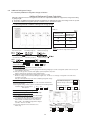
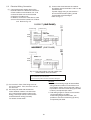
Table 8.1 Checking of Wire Connection by Test Run
NOTE: "TEST RUN" shall be performed with each refrigerant cycle (each outdoor unit).
(1) Turn ON the power source of the units.
(2) Procedure for "TEST RUN" mode of remote control switch.
Depress the "MODE" and the "CHECK" switches together
for more than 3 seconds.
Setting Temperature
Hisense
SET TEMP.
HIGH
COOL
UNIT
A/C
CHECK
RUN / STOP
Operation Lamp
If "TEST RUN" and the counting number of the
connected units with the remote control switch
(for example "05") are indicated on the remote
control switch, the connection of remote control
cable is correct.
MODE FAN SPEED
TEMP.
ON/OFF TIMER
RESET
MODE
VENTI LOUVER
If no indication appears or the number of the units
indicated is smaller than the actual number of
the units, some abnormalities exist.
CHECK
TIME
CHECK
Remote Control Switch
(3)
Remote
Control Switch
Indication
No Indication
Wrong Portions
Inspection Points after the Power Source OFF
* The power source of outdoor unit is not turned ON.
* The connection of the remote control cable
is incorrect.
* The connecting wires of power supply line
are incorrect or loosed.
1. Connecting Points of Remote Control Cable Terminal
Board of Remote Control Switch and Indoor Unit
2. Contact of Terminals of Remote Control Cable
3. Connecting Order of each Terminal Boards
4. Screw Fastening of each Terminal Boards
* The power source of outdoor unit is not turned ON.
Counting
* The operating line wiring between indoor unit and
number of
outdoor unit is not connected.
connected units
is incorrect.
Back to (1) after checking
(4) Select TEST RUNNING MODE by depressing "MODE" switch. (COOL or HEAT)
(5) Depress "RUN/STOP" switch.
The "TEST RUN" operation will be started. (The 2 hours OFF-TIMER will be set and the "TEST RUN" operation
will be finished after 2 hours unit operation or by depressing the "RUN/STOP" switch again.)
NOTE:
The "TEST RUN" operation ignores the temperature limitation and ambient temperature during heating
operation to have a continuous operation, but the protections are alive.
Therefore, the protection may activate when the heating "TEST RUN" operation is performed in high ambient temperature.
If the units do not start or the operation lamp on the remote control switch is flashed,
some abnormalities exist.
(6)
Remote Control
Switch Indication
The operation lamp
flashes. (1 time/1 sec.)
And the Unit No. and
Alarm Code "03" flash.
Unit Condition
The unit does not
start.
Wrong Portions
Inspection Points after the Power Source OFF
The power source of outdoor unit
is not turned ON.
The connecting wires of operating
line are incorrect or loosed.
1. Connecting Order of each Terminal Boards
2. Screw Fastening of each Terminal Boards
NOTE:
Recovering method of FUSE for operating circuit.
There is a fuse ("FUSE4" on Indoor Unit PCB1, "EF1"
on Outdoor Unit PCB1) to protect operating circuit
on the PCB, when the power lines are connected to
operating lines.
If fuse is melted, operating circuit can be recovered
once by setting the dip switch on the PCB, as below.
Indoor Unit PCB1
DSW7
ON
OFF
The operation lamp
flashes. (1 time/2 sec.)
Indication or flash
except above.
The operation lamp
flashes. (1 time/1 sec.)
And the Unit No. 00.
Alarm Code dd and
Unit Code E.00 flash.
1
2
* Set the switch #1 to ON position to recover the
operation circuit.
This is the same as items (3)-1 and 2.
The unit does not
start.
Remote control cable is broken.
Contact of connectors is not good.
The connection of remote control
cable is incorrect.
The unit does not
The connection of the thermistors
Check by the abnormality mode table 8.3.
start, or starts once or other connectors are incorrect.
(Do it by service people.)
and then stops.
Tripping of protector exists, or elses.
The unit does not
start.
The connection of the remote
control cable between indoor units
is incorrect.
Check by the abnormality mode table 8.3.
(Do it by service people.)
Back to (1) after checking
! Alarm Code Indication of Remote Control Switch
Abnormal Indoor
Unit No.
Abnormal Ref.
Cycle No.
Alarm Code
Model Code
Model Code
Connected No.
of Indoor Units
Indication
Alarm Code
Model
Heat-pump
Inverter
Multi
COOL MED
COOL MED
ADDS. RN
A/C
ALARM
ADDS. RN
Indicated
for a second
alternately
A/C
ALARM
24
Cooling Only
Others
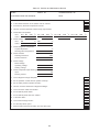
Table 8.2 Test Run and Maintenance Record
MODEL:
SERIAL. No.
COMPRESSOR MFG. No.
CUSTOMER'S NAME AND ADDRESS:
DATE:
1. Is the rotation direction of the indoor coil fan correct?
2. Is the rotation direction of the outdoor coil fan correct?
3. Are there any abnormal compressor sounds?
4. Has the unit been operated at least twenty (20) minutes?
5. Check Room Temperature
Inlet:
Outlet:
No. 1 DB
DB
/WB
/WB
o
o
C,
C,
No. 2 DB
DB
/WB
o
/WB
o
6. Check Outdoor Ambient Temperature
Inlet:
Outlet:
DB
DB
o
o
C,
C,
WB
C
C
o
7. Check Refrigerant Temperature
Liquid Temperature:
C
o
Discharge Gas Temperature:
Discharge Pressure:
Suction Pressure:
C,
o
WB
8. Check Pressure
C,
C
o
MPa
MPa
9. Check Voltage
Rated Voltage:
V
Starting Voltage:
V
Operating Voltage:
V,
10. Check Compressor Input Running Current
Input:
kW
Running Current:
A
11. Is the refrigerant charge adequate?
12. Do the operation control devices operate correctly?
13. Do the safety devices operate correctly?
14. Has the unit been checked for refrigerant leakage?
15. Is the unit clean inside and outside?
16. Are all cabinet panels fixed?
17. Are all cabinet panels free from rattles?
18. Is the filter clean?
19. Is the heat exchanger clean?
20. Are the stop valves open?
21. Does the drain water flow smoothly from the drain pipe?
25
No.3 DB
DB
/WB
/WB
o
o
C,
C,
No.4 DB
DB
/WB
/WB
C
o
C
o
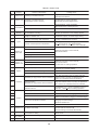
Table 8.3 Alarm Code
Code
No.
Category
01
Indoor Unit
Activating of Protection Device
02
Outdoor Unit
Activating of Protection Device
(Except Alarm Code 41 and 42)
03
04
Transmission
05
Supply
Phases
06
Voltage Drop
07
08
Cycle
11
12
13
14
22
24
Sensor on
Indoor Unit
High Water Level in Drain Pan,
Activated Float Switch.
Activated High Pressure Switch.
Locked Motor in Cooling Operation.
Abnormality of Power Supply Phase
Abnormality between Indoor and Outdoor
Incorrect Wiring. Loose Terminals,
Disconnected wire, Tripping of Fuse.
Abnormality between Inverter and Control PCB
Failure in Transmission of PCB for Inverter.
Abnormality of Power Supply Phases
(for 220V/60Hz Unit Only)
Abnormal Waveform of one or more the Supply
Phases (Ex. Distortion of the Voltage Signal).
Decrease of Discharge Gas Superheat
Discharge Gas SUPERHEAT less than
10 deg. is maintained for one hour.
Temperature of the top of Compressor: Td
Td > 127oC(Cooling), Td > 120oC(Heating)
over 10 minutes, or Td > 140oC over 5 seconds.
Voltage Drop by Excessively Low or High
Voltage to Outdoor Unit
Increase of Discharge Gas Temperature
Outlet Air Thermistor
Sensor on
Outdoor Unit
Gas Piping Thermistor
Activated Internal Thermo of Fan Motor.
Compressor Thermistor
Failure of Thermistor, Loose Terminal,
Disconnected Wire.
Locked Motor in Heating Operation.
Outdoor Air Thermistor
Evaporating Thermistor
Incorrect Capacity of Outdoor and Indoor Unit
System
Voltage Drop of Power Supply
Insufficient Capacity of Power Supply Wiring.
Failure of Thermistor, Loose Terminal,
Disconnected Wire.
Freeze Protection Thermistor
Tripping of Protection Device
31
35
Leading Cause
Inlet Air Thermistor
19
20
Content of Abnormality
Incorrect Setting of Capacity Combination or
Incorrect O.U. Capacity Setting.
Incorrect Indoor Unit No. Setting
Duplication of Indoor Unit No.
38
Abnormality of Protective Circuit in outdoor Unit
Failure of Protection detecting Circuit
41
Overload cooling
(Possibility of high pressure device activation.)
42
Pressure
Overload heating
(Possibility of high pressure device activation.)
47
Activation of Low Pressure Decrease
Protection Device
51
Abnormality of Current Sensor for Inverter
52
Overcurrent Protection Activation
53
Inverter
Inverter Fin Temperature Increase
55
IPM or PCB2 Abnormality
57
Outdoor Fan
59
Inverter
b1
Indoor Unit
No. Setting
EE
Compressor
Stoppage by Excessively Decrease of evaporating
Temperature ( Te < -35oC) is activated 3 times in
one hour, Locked Motor in Heating Operation.
Failure of Control PCB1, IPM or PCB2
Failure of IPM or PCB2, Clogging of Heat Exchanger.
IPM or PCB2 Abnormality
Failure of Compressor, clogging of Heat Exchanger.
Protection Activation of IPM or PCB2
54
O.U. Pipe Thermistor Temp. is Higher than 55oC
and the Comp. Top Temp. is Higher than 95oC
when O.U. Protection Device is activated.
I.U. Freeze Protection Thermistor Temp. is Higher
than 55oC and the Comp. Top Temp. is Higher than
95oC when O.U. Protection Device is activated.
Abnormal Inverter Fin Thermistor,
Clogging of Heat Exchanger
Abnormal Outdoor Fan
Failure of IPM or PCB2
Disconnected wire or Incorrect wiring between
Control PCB and Inverter PCB.
Incorrect Wiring or Fan Motor Abnormality
Fan Motor Abnormality
Thermistor of Inverter Fin Abnormality
(for Inverter Fin Temp.)
Loose Connector, Disconnected Wire,
Short Circuit
Incorrect Unit No. Setting
Over 64 I.U. Setting by Ref. No. or I.U. Address.
Compressor Protection Alarm
Failure of Compressor.
26
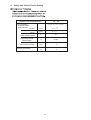
9.
Safety and Control Device Setting
38 ~ 54
Outdoor Unit Model(KBtu/h)
For Compressor
Pressure Switch
High Pressure
Automatic Reset,Non-Adjustable
Cut-Out
Cut-In
Fuse on Main Circuit
Compressor Crank
-0.05
M Pa
4.15 -0.20
M Pa
3.2 -0. 20
+ 0.15
A
50
W
60 +28
Heater Power
Non-Adjustable
CCP Timer Set Time
Control Circuit Fuse
Min
3
A
5
27
Hisense Corporation
Add: 17,Donghai Xi Road,Qingdao 266071,China
P00415Q
2013.05
V04