1
Model 3000/500
and Micro 3100/505
Vo l u m e t r i c I n f u s i o n
Pump
Te c h n i c a l S e r v i c e
Manual
0473
Graseby Medical Ltd.
Vo l u m e t r i c I n f u s i o n P u m p s
Warnings
Warnings tell you about dangerous conditions, that could lead to death or serious injury to
the user or patient, that can occur if you do not obey all of the instructions in this manual.
1.
WARNING: You should ensure that the performance offered by the pump is fit for the intended purpose.
Failure to do so may result in compromised function of the product, patient injury or user injury.
2.
WARNING: Do not use a faulty pump. If the pump detects a fault when it is first turned on, or if it develops a
fault during operation then a continuous system alarm sounds. The pump must be referred to a suitably
qualified technician or returned to Graseby Medical in order to have the fault rectified.
3.
WARNING: Before using the pump, it should be inspected for physical damage. The pump should not be
used if damage is evident, and should be returned to service personnel for repair before being returned to
use. Failure to do so may result in compromised function of the product, patient injury or user injury.
4.
WARNING: Do not use the pump if you detect any cracks, chips and loose or bent parts, or if the buttons do
not move in and out freely when they are pressed. Failure to do so could cause inadvertent disconnection
of the pumps.
5.
WARNING: Do not push or pull on the pumps, or the IV pole may tip over or the pumps fall to the floor. Do
not try to remove modular connected pumps from the IV pole whilst they are joined together. Either of
these could cause the administration set to separate from the fluid container thus spilling the medication,
or the pumps themselves could be damaged.
6.
WARNING: Correct entry of data is essential in order to ensure that the intended infusion is performed.
Before confirming any displayed data when setting up an infusion, you should ensure that it is correct.
Failure to do so may result in compromised function of the product, patient injury or user injury.
7.
WARNING: Dose-rate calculation requires care in entering data. Refer to specific product drug labelling for
information on appropriate administration techniques and dosages. Entering incorrect data may result in
patient injury or death.
8.
WARNING: When delivering drugs in the epidural space, use only those medications specifically indicated
for epidural use. Epidural administration of other drugs could result in serious patient injury or death.
9.
WARNING: The use of administration sets incorporating injection sites could lead to an improper or
inappropriate infusion resulting in serious patient injury or death.
10. WARNING: Failure to clearly identify the pump and administration sets could lead to an improper or
inappropriate infusion resulting in serious patient injury or death.
11. WARNING: Remove any air to prevent air embolism. The presence of air within the infusion can result in
complications resulting in patient injury or death.
12. WARNING: To avoid over infusion, do not prime the infusion line when the administration set is connected
to the patient. Over infusion can result in patient injury or death.
13. WARNING: The Occlusion alarm level must be checked before starting an infusion to ensure that it is
appropriate for the infusion. Failure to do so may result in an unacceptably slow time to Occlusion alarm,
resulting in patient injury or death.
14. WARNING: Prior to starting an infusion, inspect the fluid path for kinks, a closed clamp or other
obstructions. Failure to do so may result in the infusion not being delivered correctly, resulting in patient
injury or death.
15. WARNING: If using a blood pressure cuff above the patient’s venipuncture site take extra care in setting
the Occlusion alarm pressures. Failure to do so may result in unnecessary Occlusion alarms, resulting in
patient injury or death.
16. WARNING: The Occlusion detection system measures downline pressure in the administration set, but
does not detect infiltration. In accordance with local protocol, you must periodically inspect the patient’s
infusion site for signs of infiltration. Failure to do so may result in an unacceptably slow time to Occlusion
resulting in patient injury or death.
17. WARNING: If an Occlusion alarm occurs, immediately clamp the line to the patient. Then inspect the fluid
pathway to determine what has caused the obstruction. An unintentional bolus of medication can result in
patient injury or death.
18. WARNING: Do not run parallel infusion lines below the pump. Delivering a Secondary infusion means
running a second line above the pump. Failure to do so may result in an inaccurate delivery of medication,
resulting in patient injury or death.
19. WARNING: Check the Secondary set carefully, since an occlusion above the pump on the Secondary line
could cause the Primary fluid to be delivered instead of the Secondary infusion. Administering the wrong
medication may cause serious patient injury or death.
3000/3100 and 500/505 Service Manual
Issue A (April 2002)
Vo l u m e t r i c I n f u s i o n P u m p s
Graseby Medical Ltd.
20. WARNING: The Secondary volume to be infused must match the amount of fluid in the secondary
container. Primary flow resumes when the secondary container is empty. If the volumes do not
correspond, the wrong infusion may be delivered which could cause serious patient injury or death.
21. WARNING: Correct management of battery charging, as described in this documentation is essential to
ensure that the pump can operate on battery for the time specified. Failure to do so may result in
compromised function of the product or patient injury.
22. WARNING: If a backup alarm sounds, the pump should be immediately removed from the patient and sent
to be repaired by a Graseby Medical qualified technician. Failure to do so may cause patient injury or
death.
23. WARNING: Failure to use the power cord retainer means that the pump may be accidentally or erroneously
disconnected from the mains. Although there is a battery backup in case this happens, the battery may not
be charged sufficiently. Consequently, there is a risk of the pump not functioning which could lead to
patient injury or death.
24. WARNING: Do not open the pump housing. Refer all service faults only to qualified technical personnel.
Opening the pump housing may cause electric shock leading to patient or user injury or death.
25. WARNING: When the pump is carrying out an infusion, to ensure that electrical safety is maintained, only
items of equipment that conform to EN60950 are to be connected to the RS232 connector situated at the
back of the pump, otherwise patient safety may be compromised.
26. WARNING: While Graseby Medical Limited have taken all reasonable steps to ensure that the pump
operates correctly while under remote control, it is the responsibility of the person who designs and
implements the controlling device to ensure that the resulting system (pump and controlling device) is fit
for its intended purpose. Failure to do so may result in compromised function of the product, patient injury
or user injury.
27. WARNING: Use only Graseby Medical administration sets with this product. Failure to do so may result in
compromised system accuracy leading to complications resulting in patient injury or death.
28. WARNING: Do not perform these tests while the pump is in use on a patient, as this may cause patient
injury or death.
29. WARNING: Unplug the AC power cord before opening the pump housing to avoid risk of electric shock,
which could result in death or serious injury.
30. WARNING: Potentially dangerous voltages are exposed when the pump housing is open and the AC power
cord is plugged in. These voltages are present in the transformer and AC fuse on the CPU/Power supply
board and the RFI line filter where the power cord connects. To avoid electric shock with potential for
severe injury or death, do not touch these areas when the power cord is plugged in.
Issue A (April 2002)
3000/3100 and 500/505 Service Manual
Graseby Medical Ltd.
Vo l u m e t r i c I n f u s i o n P u m p s
Cautions
Cautions tell you about dangerous conditions that can occur and cause damage to the pump
if you do not obey all of the instructions in this manual.
1.
CAUTION: Refer all service, repair and calibrations only to qualified technical personnel. Unauthorised
modifications to the pump must not be carried out.
2.
CAUTION: Do not autoclave, steam sterilize, ETO sterilise or subject the pump to temperatures in excess
of 45° C (113° F). Excessive temperatures may cause damage to the pump.
3.
CAUTION: To prevent serious damage to the pump it must not be immersed in any liquids or exposed to
strong organic solvents. Wipe off spills immediately. Do not allow fluid or residues to remain on the pump.
Additionally, the pump is not designed to allow it to be sterilised. Failure to observe these cautions may
cause internal damage to the pump.
4.
CAUTION: Carry out periodic cleaning following the detailed instructions in this manual Do not use
unapproved cleaning agents.
5.
CAUTION: When turning the pump on, if screens similar to those illustrated are not displayed, do not use
the pump, and send the pump to authorised service personnel.
6.
CAUTION: Only carry the pump by the handle. Failure to do so may result in damage to the pump, or the
pump may be dropped which could cause internal damage to the pump.
7.
CAUTION: The backlight has a limited life and may, if used constantly, cause the light to dim. Eventually the
message display may then need to be replaced. To preserve the life of the message display, you should
only turn on the Message Display Light as described here if it is specifically required. Misuse of this
feature could lead to both battery and LCD depletion.
8.
CAUTION: The Functional and Accuracy Check should be performed following any significant disassembly
or repair of the pumps.
9.
CAUTION: The circuit boards consist primarily of surface mounted technology, component level repairs
are not recommended.
10. CAUTION: Disconnect the battery connection P104 on I/O board before disassembling the circuit boards to
avoid circuit damage. After disconnecting P104, press the On/Off key twice to discharge the circuitry.
11. CAUTION: Handling of printed circuit boards is required during disassembly/assembly. A static controlled
work station including a conductive mat and grounded wrist strap should be used to provide protection
against electrostatic discharge (ESD) or circuit board damage could result.
12. CAUTION: Do not use a screwdriver or other sharp instrument to separate the front and rear housing as
this action could cause pump damage.
13. CAUTION: Do not damage or puncture the kapton tape. If the tape is damaged or punctured it could result
in the pump not being ESD protected. Special care should be taken when placing the kapton tape and also
when assembling the front and rear cases together as the front case lugs may puncture the tape.
14. CAUTION: Crossed wires must be shielded with suitable insulation as described. Failure to carry out the
procedure as specified may result in permanent damage to the LCD.
3000/3100 and 500/505 Service Manual
Issue A (April 2002)
Vo l u m e t r i c I n f u s i o n P u m p s
Issue A (April 2002)
Graseby Medical Ltd.
3000/3100 and 500/505 Service Manual
Graseby Medical Ltd.
Vo l u m e t r i c I n f u s i o n P u m p s
Published by Graseby Medical Limited.
All possible care has been taken in the preparation of this
publication, but Graseby Medical Limited accepts no liability for any
inaccuracies that may be found.
Graseby Medical reserves the right to make changes without notice
both to this publication and to the product which it describes.
©
Graseby Medical Limited 2002
No part of this publication may be reproduced, transmitted,
transcribed, or stored in a retrieval system or translated into any
human or computer language in any form by any means without the
prior permission of Graseby Medical Limited.
GRASEBY MEDICAL LTD,
Colonial Way,
Watford,
Hertfordshire,
UK
WD24 4LG
TEL:
FAX:
WEB:
(+44) (0)1923 246434
(+44) (0)1923 231595
www.graseby.co.uk
REGISTERED IN ENGLAND
COMPANY No. 995550
Trademarks and acknowledgements:
Graseby; and Smiths are all trademarks of the Smiths Group plc.
All other trademarks are acknowledged as the property of their
respective owners.
3000/3100 and 500/505 Service Manual
Issue A (April 2002)
Contents — i
Vo l u m e t r i c I n f u s i o n P u m p s
Graseby Medical Ltd.
ISSUE RECORD
Issue No.
A
Contents — ii
Reason for change
Pages
effected
Date
Initial issue
All
April 2002
Issue A (April 2002)
3000/3100 and 500/505 Service Manual
Graseby Medical Ltd.
Vo l u m e t r i c I n f u s i o n P u m p s
Contents
Chapter 1 - Introduction
Introduction
Scope of this manual ...................................................................................................... 1 - 1
Related manuals ............................................................................................................ 1 - 1
Graseby service contacts .............................................................................................. 1 - 1
Product Overview ............................................................................................................. 1 - 2
System description ........................................................................................................ 1 - 2
Optional labels ................................................................................................................ 1 - 2
Software versions .......................................................................................................... 1 - 2
Chapter 2 - Specification
Specifications.................................................................................................................... 2 - 1
Standards .......................................................................................................................... 2 - 8
Trumpet curves ................................................................................................................. 2 - 9
Chapter 3 - Overview of Pump Operation and Initial Checks
Overview of Pump Operation & Initial Checks .............................................................. 3 - 1
Exterior of the 500/3000 pump - front ............................................................................. 3 - 2
Exterior of the pump - rear ............................................................................................. 3 - 3
How the pump is powered .............................................................................................. 3 - 4
How the pump works ..................................................................................................... 3 - 5
Power up tests and checks ............................................................................................ 3 - 9
Powering down ............................................................................................................. 3 - 12
Power monitoring .......................................................................................................... 3 - 13
Alarms .......................................................................................................................... 3 - 15
Chapter 4 - Volumetric Pumps Menus
Volumetric Pump Menus .................................................................................................. 4 - 1
Which version of software is in the pump? ..................................................................... 4 - 1
Introduction to menus ..................................................................................................... 4 - 1
About the Technician menu ............................................................................................ 4 - 2
Summary of Technician menu parameters ..................................................................... 4 - 3
Using Technician parameters ......................................................................................... 4 - 4
About the Biomedical menu ............................................................................................ 4 - 8
Summary of Biomedical menu parameters .................................................................. 4 - 10
3000/3100 and 500/505 Service Manual
Issue A (April 2002)
Contents — iii
Vo l u m e t r i c I n f u s i o n P u m p s
Graseby Medical Ltd.
About Snapshot screens .............................................................................................. 4 - 11
Decoding Snapshot screen-a....................................................................................... 4 - 12
Decoding Snapshot screen-b....................................................................................... 4 - 15
Using Biomedical Parameters ...................................................................................... 4 - 22
Enabling special programming functions ...................................................................... 4 - 27
About the Service Functions menu .............................................................................. 4 - 29
Service Functions menu parameters ........................................................................... 4 - 30
Chapter 5 - Mechanical Systems
Mechanical Systems ......................................................................................................... 5 - 1
Linkage system .............................................................................................................. 5 - 1
Cassette housing and door ............................................................................................ 5 - 2
Safety clip retention slot ................................................................................................. 5 - 2
Cam housing switch and safety clip switch ................................................................... 5 - 4
Cam housing .................................................................................................................. 5 - 4
Stepping motor ............................................................................................................... 5 - 4
Cams, pistons and valves of the pumping mechanism .................................................. 5 - 6
Encoder wheel and interrupter ....................................................................................... 5 - 9
Empty bag contacts ..................................................................................................... 5 - 10
Sensors ........................................................................................................................ 5 - 10
Pole clamp and IV pole ................................................................................................. 5 - 12
Modular connection system ......................................................................................... 5 - 12
Chapter 6 - Electronic Circuits
Electronic Circuits ............................................................................................................ 6 - 1
Definitions....................................................................................................................... 6 - 1
Functional block diagram ............................................................................................... 6 - 1
System control ............................................................................................................... 6 - 2
Power ............................................................................................................................. 6 - 2
Interconnection summary ............................................................................................... 6 - 3
PCB design .................................................................................................................... 6 - 3
CPU/power supply board ............................................................................................... 6 - 3
Power supply .................................................................................................................. 6 - 9
I/O board ...................................................................................................................... 6 - 11
Display board ............................................................................................................... 6 - 14
RS232 interface ........................................................................................................... 6 - 17
Contents — iv
Issue A (April 2002)
3000/3100 and 500/505 Service Manual
Graseby Medical Ltd.
Vo l u m e t r i c I n f u s i o n P u m p s
Chapter 7 - Maintenance Procedures
Maintenance Procedures ................................................................................................. 7 - 1
Introduction..................................................................................................................... 7 - 1
Recommended test equipment ....................................................................................... 7 - 2
Recommended troubleshooting equipment .................................................................... 7 - 2
Service tool kit ................................................................................................................ 7 - 3
Periodic cleaning ............................................................................................................ 7 - 4
Recommended yearly checks and tests........................................................................ 7 - 6
Recommended Functional & Accuracy Tests:
Checklist .......................................................................................................................... 7 - 18
Troubleshooting .............................................................................................................. 7 - 19
Replacing the LCD ....................................................................................................... 7 - 23
Reinitialising the pump after replacing the NVRAM (IC18) ........................................... 7 - 25
Adjustment of the “Cassette Fitted” micro switch ......................................................... 7 - 32
Chapter 8 - Disassembly and Reassembly Instructions
Disassembly and reassembly instructions .................................................................... 8 - 1
Battery removal .............................................................................................................. 8 - 1
AC fuse removal ............................................................................................................ 8 - 1
Front housing removal .................................................................................................... 8 - 2
Door assembly removal ................................................................................................. 8 - 3
CPU/Power supply board removal ................................................................................. 8 - 5
I/O board assembly removal .......................................................................................... 8 - 6
Display board assembly removal ................................................................................... 8 - 7
Membrane switch replacement - old case ...................................................................... 8 - 8
Membrane switch replacement - new case .................................................................... 8 - 9
Pump assembly removal .............................................................................................. 8 - 10
Motor assembly removal .............................................................................................. 8 - 11
Realignment of motor coupler....................................................................................... 8 - 12
Cassette housing disassembly .................................................................................... 8 - 13
Safety clip mechanism disassembly ............................................................................ 8 - 13
Cam housing switch disassembly ................................................................................ 8 - 14
Calibration and adjustment of components ................................................................. 8 - 15
Cam housing switch adjustment .................................................................................. 8 - 15
Occlusion alarm adjustment ......................................................................................... 8 - 16
Voltage Checks ............................................................................................................... 8 - 18
Power supply voltage check ........................................................................................ 8 - 18
Low and dead battery alarm check .............................................................................. 8 - 21
3000/3100 and 500/505 Service Manual
Issue A (April 2002)
Contents — v
Vo l u m e t r i c I n f u s i o n P u m p s
Graseby Medical Ltd.
Chapter 9 - Illustrated Parts List
Illustrated Parts List for pump Serial numbers
from 3000 to 60,000 ........................................................................................................... 9 - 1
General assembly of the volumetric pump ..................................................................... 9 - 2
Pump assembly ............................................................................................................. 9 - 8
Rear housing assembly ................................................................................................. 9 - 9
Display board assembly ............................................................................................... 9 - 12
CPU power supply/RS232 board assembly ................................................................ 9 - 14
I/O board assembly ...................................................................................................... 9 - 16
Illustrated Parts List for Serial numbers from 60,000 ................................................. 9 - 17
General assembly of the volumetric pump ................................................................... 9 - 18
Pump assembly ........................................................................................................... 9 - 22
Rear housing assembly ............................................................................................... 9 - 23
Display board assembly ............................................................................................... 9 - 25
CPU power supply/RS232 board assembly ................................................................ 9 - 26
I/O board assembly ...................................................................................................... 9 - 27
Chapter 10 - Electrical Diagrams
Electrical Diagrams ........................................................................................................ 10 - 1
Introduction................................................................................................................... 10 - 1
Overall functional block diagram .................................................................................. 10 - 2
Power routeing block diagram ...................................................................................... 10 - 3
Electrical routeing block diagram ................................................................................. 10 - 4
Display board schematic .............................................................................................. 10 - 5
CPU/Power supply schematic (sheet 1 of 3) ............................................................... 10 - 6
CPU/Power supply schematic - CE (sheet 2 of 3) ....................................................... 10 - 7
CPU/Power supply circuit (sheet 3 of 3) ....................................................................... 10 -8
Input/Output schematic ................................................................................................. 10 -9
RS232 schematic ........................................................................................................ 10 -10
Chapter 11 - Waveform Diagrams
Waveform Diagrams..................................................................................................... 11 - 1
Introduction................................................................................................................... 11 - 1
Contents — vi
Issue A (April 2002)
3000/3100 and 500/505 Service Manual
Graseby Medical Ltd.
Vo l u m e t r i c I n f u s i o n P u m p s
Chapter 12 - Remote monitoring and controlling of the pump
Remote monitoring and controlling of the pump ........................................................ 12 - 1
Introduction................................................................................................................... 12 - 1
Organisation of this chapter ......................................................................................... 12 - 1
Summary of commands - Version 0.67 and below....................................................... 12 - 2
Protocol definition ......................................................................................................... 12 - 2
Record Format - Version 0.67 and below .................................................................... 12 - 3
Command Codes ......................................................................................................... 12 - 3
Error Processing .......................................................................................................... 12 - 7
Summary of hardware connection and handshaking ................................................... 12 - 7
Example Commands .................................................................................................... 12 - 8
Interfacing with pump software version 0.68 and above ............................................ 12 - 9
Model 3000/500 3100/505 Computer Interface ............................................................ 12 - 9
Protocol Definition ........................................................................................................ 12 - 9
Character ..................................................................................................................... 12 - 9
Format - version 0.68 and above ............................................................................... 12 - 10
Command Record Format - version 0.68 and above ................................................. 12 - 11
Return Record Format ............................................................................................... 12 - 15
Command Summary .................................................................................................. 12 - 18
Pump Powered Down - AC/Battery ............................................................................ 12 - 23
Exiting CI Mode - Terminated vs. Disabled ................................................................. 12 - 23
Response Time-outs and Error Processing ............................................................... 12 - 24
Summary of Handshaking and Hardware Connection ............................................... 12 - 24
Example Commands .................................................................................................. 12 - 25
3000/3100 and 500/505 Service Manual
Issue A (April 2002)
Contents — vii
Introduction
Chapter 1
Graseby Medical Ltd.
Vo l u m e t r i c I n f u s i o n P u m p s
Introduction
1
Scope of this manual
This manual is aimed at service personnel to enable them to service
and repair the Volumetric range of pumps. It has been revised and
updated to cover the Version 0.71 pump software, and where
appropriate it describes and illustrates the revised case design (for
pumps with serial numbers from 60,000). However, the manual is
backwards compatible with all earlier versions of pump software and
case design.
Related manuals
Refer to the Instruction Manual and Technical User Manual when
more detailed operating information is required, since this is outside
the scope of the Service Manual. The following manuals are
applicable to the Volumetric Infusion Pumps with Version 0.71
software and are listed in Chapter 9 Illustrated Parts List:
Instruction Manual and Technical User Manual - old case
design, see pages 9-6 and 9-7 for part numbers
Instruction Manual and Technical User Manual - new case
design, see page 9-21 for part numbers
The Instruction Manuals for Version 0.67 and earlier software are
listed in the first section of Chapter 9 Illustrated Parts List, see page
9-6.
Graseby service contacts
If you have any queries or problems with your pump that cannot be
solved by this manual, please contact the appropriate Service Centre.
UK service address
GRASEBY MEDICAL LIMITED
COLONIAL WAY
WATFORD
HERTFORDSHIRE
WD24 4LG
ENGLAND
TEL:
(+44) (0)1923 246434
FAX:
(+44) (0)1923 447773
Website: www.graseby.co.uk
USA service address
DELTEC INC.
1265 GREY FOX ROAD
ST PAUL
MINNESOTA
55112
U.S.A.
3000/3100 and 500/505 Service Manual
TEL:
001 651 633 2556
TOLL FREE 0800 433 5832
FAX: 001 651 628 7459
Website: www.deltec.com
Issue A (April 2002)
1 — 1
Vo l u m e t r i c I n f u s i o n P u m p s
Graseby Medical Ltd.
Product Overview
1
System description
The Model 3000/500 and Micro 3100/505 Volumetric Infusion
pumps, including the dedicated administration sets, are for use by
trained medical professionals in the intravenous and intra-arterial
delivery of fluid and medications. In addition, they may be used for
epidural delivery.
Note: Graseby Volumetric Infusion Pumps are also known as the Model 500
and Micro 505. With the exception of the numbering the 3000/500 and
the 3100/505 versions of the pumps are identical.
Optional labels
To assist users to differentiate the pump and IV set being used for
epidural delivery, from those being used for other infusions, a yellow
Epidural Label Set for the Volumetric Infusion Pump (part no. TPF00306) is available from Graseby Medical Ltd.
Software versions
If a pump label lists more than eight options, Version 0.71 software is
installed. If there are fewer options, the pump has an earlier version
of software. You can find out the software version of the pump by
checking on the Biomedical Menu, see Chapter 4, Volumetric Pump
Menus.
1 — 2
Issue A (April 2002)
3000/3100 and 500/505 Service Manual
Graseby Medical Ltd.
Vo l u m e t r i c I n f u s i o n P u m p s
About Version 0.71
The new software contains some completely new features as well as
improvements to existing features. These include many new
configurable options such as selectable default settings for the
occlusion alarm levels, Primary/Secondary Rate and Volume to be
Infused selectable minimum and maximum limits, drug library and
bolus functions. Added to this, the Quick Rate Change option is now a
configurable feature, and may be enabled or disabled as required.
For a complete list of the functions please see the new Volumetric
Instruction Manual and the Technical User Manual.
Upgrading to Version 0.71
It is possible to upgrade earlier Graseby Medical Volumetric range
pumps to the latest software version 0.71. For 3000/500 pumps order
part no. 0150-0671 and for 3100/505 pumps order part no. 0150-0672
(note these are English only kits). The upgrade kit contains the
following items:
V0.71 CPU Board Prom
3.66A Display Prom
Keypad Overlay (3000/500, 3100/505)
Keypad
Start up Label
Overlabel (3100/505)
Lower door recess label
Instruction Manual
Technical User Manual
Instructions for upgrade.
3000/3100 and 500/505 Service Manual
Issue A (April 2002)
1 — 3
1
Specification
Chapter 2
Graseby Medical Ltd.
Vo l u m e t r i c I n f u s i o n P u m p s
Specifications
General
Weight
5 kg (11 pounds).
Dimensions
for pumps with serial numbers from 3000 to 59,999
including pole clamp
Height
25 cm (10 inches).
Width
21.5 cm (8.6 inches).
Depth
23.5 cm (9.45 inches).
for pumps with serial numbers from 60,000
including pole clamp
Height
28 cm (11 inches).
Width
21.5 cm (8.6 inches).
Depth
23.5 cm (9.45 inches).
Temperature
Operating 18° to 40° C (64° to 104° F)
Storage -25° to +55° C (-13° to 131° F).
Relative humidity
Operating 30% to 75% (non-condensing).
Storage 30% to 75% (non-condensing).
Pressure range
Operating 50 kPa to 106 kPa
Storage 19 kPa to 106 kPa
Immunity levels
Immunity levels are the full levels specified in
EN60601-1-2 (radiated immunity is 3 V/m and
ESD immunity is 3 kV contact and 8 kV air).
Free flow protection
The pump mechanism operates the safety clip on
the administration set.
Head-height
From bottom of drip chamber to top of pump
Model 3000/500
15
30
30
30
cm (6 ins) minimum for flow rates <500 mL/h
cm (12 ins) minimum for flow rates >500 mL/h
cm (12 ins) when using 60 drops/mL sets
cm (12 ins) when using thick solutions*
Micro 3100/505
15 cm (6 ins) minimum
30 cm (12 ins) when using 60 drops/mL sets
30 cm (12 ins) when using thick solutions*
* certain cytotoxic agents, lipid-based fluids and
other viscous solutions, for example Total
Parenteral Nutrition.
3000/3100 and 500/505 Service Manual
Issue A (April 2002)
2 — 1
2
Vo l u m e t r i c I n f u s i o n P u m p s
2
Graseby Medical Ltd.
Self test
Dual microprocessors independently test each other.
Maximum over infusion
Under a single-fault condition, the maximum over
infusion that may occur is 12.5% over the selected
flow rate. Larger inaccuracies are detected by the
pump, and cause it to stop infusing and to alarm.
Air detect system
Air bubbles are detected by electronic optoencoder detection device (with self-checking
sensors) located on cassette housing.
Accuracy
± 2% of displayed rate and volume to be infused.
The quoted accuracy is ±2% for a long-term
infusion.
Below rates of 1 mL/h this accuracy may not be
achieved for a short-term infusion.
During the total infusion time the accuracy
averages out (see trumpet curves in this
chapter).
Accuracy measurement equipment
Test solution
50 mL glass measurement burette graduated in
0.1 mL increments and traceable to National
Institute of Standards and Technology or
appropriate international standards bureau.
Sterile water or normal saline at room
temperature (70°F ±5°/21°C ±3°).
Graseby standard (primary), 20 drops/mL, noncheckvalve administration set (8C820).
Testing conditions
Model 3000/500
Micro 3100/505
fluid level in the solution container 46 cm (18
inches) above top of the pump, rate set at
999 mL/h and volume to be infused of 49 mL.
fluid level in the solution container 46 cm
(18 inches) above top of the pump, rate set at
99.9 mL/h and volume to be infused of 25.0 mL.
Accessories
For a complete list of Administration Sets, please contact Graseby
Medical or your local distributor.
2 — 2
Issue A (April 2002)
3000/3100 and 500/505 Service Manual
Graseby Medical Ltd.
Vo l u m e t r i c I n f u s i o n P u m p s
Power
AC power supply
Internally configured for either
100-120 V AC, 200 mA, 50/60 Hz.
or,
220-240 V AC, 80 mA, 50/60 Hz.
Battery type
Rechargeable, sealed lead-acid, 12 Volt, 1.3 Ah.
Battery operating time
6 hours at 100 mL/h (99.9 mL/h on Micro 3100/505),
with approximately 1/2 hour warning of discharged
battery.
Battery recharge time
Approximately 10 hours, depending on the
operating conditions. The batteries will be
charging during an infusion.
Leakage current
100 to 120 V less than 20 microamps ungrounded
or,
220 to 240 V less than 50 microamps ungrounded
This is measured between the ground stud and
the earth protective prong of the AC mains
connector.
Over-current protection
Voltage
AC line fuse
Thermal fuse
Battery fuse
100 to 120 V
200 mA
130°
1.0 amp
220 to 240 V
2 x 80 mA
130°
1.0 amp
Note: All fuses are time delay fuses
3000/3100 and 500/505 Service Manual
Issue A (April 2002)
2 — 3
2
Vo l u m e t r i c I n f u s i o n P u m p s
Graseby Medical Ltd.
Primary and Secondary Infusions
Rate range
Model 3000/500
2
Range
0.1 to 99.9 mL/h
1 to 999 mL/h
Range
0.1 to 99.9 mL/h
Increment
0.1 mL/h
1 mL/h
Increment
0.1 mL/h
Range
0.1 to 999.9 mL
1 to 9999 mL
Range
0.1 to 999.9 mL
Increment
0.1 mL
1 mL
Increment
0.1 mL
Range
0.1 to 99.9 mL/h
1 to 400 mL/h
Range
0.1 to 99.9 mL/h
Increment
0.1 mL/h
1 mL/h
Increment
0.1 mL/h
Model 3000/500
Range
0.1 to 999.9 mL
1 to 4400 mL
Increment
0.1 mL
1 mL
Micro 3100/505
Range
0.1 to 999.9 mL
Increment
0.1 mL
Range
0 to 59 minutes
0 to 48 hours
Increment
1 minute
1 hour
Range
0.1 to 99.9 mL/h
1 to 999 mL/h
Range
0.1 to 99.9 mL/h
Increment
0.1 mL/h
1 mL/h
Increment
0.1 mL/h
Micro 3100/505
Volume to be infused
Model 3000/500
Micro 3100/505
Rate Taper Infusions
Rate range
Model 3000/500
Micro 3100/505
Volume to be infused
Time range
All pumps
Volume Over Time Infusions
Rate range
Model 3000/500
Micro 3100/505
2 — 4
Issue A (April 2002)
3000/3100 and 500/505 Service Manual
Graseby Medical Ltd.
Vo l u m e t r i c I n f u s i o n P u m p s
Volume to be infused range
Model 3000/500
Range
0.1 to 99.9 mL
1 to 9999 mL
Range
0.1 to 99.9 mL
1 to 999 mL
Increment
0.1 mL
1 mL
Increment
0.1 mL
1 mL
Range
0 to 59 minutes
0 to 48 hours
Increment
1 minute
1 hour
Range
0.01 to 99.99
0.1 to 999.9
1 to 9999
Increment
0.01
0.1
1
Range
0.10 to 99.99 kg
0.1 to 453 kg
0.22 to 99.99 lbs
0.2 to 999 lbs
Increment
0.01 kg
0.1 kg
0.01 lbs
0.1 lb.
Mode
MG drug/bag
Range
0.01 to 99.99
0.1 to 999.9
1 to 99999
Increment
0.01
0.1
1
Gm drug/bag
0.01 to 99.99
0.1 to 99.9
1 to 999
0.01
0.1
1
mcg drug/bag
0.01 to 9.99
0.1 to 99.9
1 to 9999
0.01
0.1
1
units/bag
0.01 to 99.99
0.1 to 999.9
1 to 99999
0.01
0.1
1
Micro 3100/505
2
Time range
All pumps
Dose-Rate Calculation Infusions:
Dose range
Body weight range
Units
Kilograms (kg)
Pounds (lbs)
Drug amount modes/range
3000/3100 and 500/505 Service Manual
Issue A (April 2002)
2 — 5
Vo l u m e t r i c I n f u s i o n P u m p s
Graseby Medical Ltd.
Rate range
2
Model 3000/500
Range
0.1 to 99.9 mL/h
1 to 999 mL/h
Increment
0.1 mL/h
1 mL/h
Micro 3100/505
Range
0.1 to 99.9 mL/h
Increment
0.1 mL/h
Model 3000/500
Range
0.1 to 999.9 mL
1 to 9999 mL
Increment
0.1 mL
1 mL
Micro 3100/505
Range
0.1 to 999.9 mL
Increment
0.1 mL
Volume to be infused range
Occlusion sensing
Alarm levels (approximate values)
Pressure units
Low
Medium
High
mmHg
103 mmHg
259 mmHg
517 mmHg
psi
2 psi
5 psi
10 psi
kPa
13.5 kPa
34.5 kPa
68.9 kPa
Time to occlusion
This table shows the maximum (measured +25%) delay times for
activation of the Occlusion below pump alarm:
Rate
Low Occlusion setting
max time to alarm
High occlusion setting
max time to alarm
1 mL/h
11 min, 5 sec.
1 hour, 10 min.
25 mL/h
15 sec.
2 min, 35 sec.
KVO rate
Default KVO rate
3.0 mL/h, or at the programmed rate if set at less than these values.
Configurable KVO rates (Version 0.71 software and above)
2 — 6
Model 3000/500
0.1 to 10.0 mL/h
Micro 3100/505
0.1 to 3.0 mL/h
Issue A (April 2002)
3000/3100 and 500/505 Service Manual
Graseby Medical Ltd.
Vo l u m e t r i c I n f u s i o n P u m p s
Symbols used on the pump
Front panel symbols
Battery is charging/mains power
applied.
Audio alarm silence button.
Side panel symbols
Use pump only in upright
position.
Rear panel symbols
Inside battery door symbols
Attention: dangerous voltages, risk
of electric shock if the housing is
opened.
Equipotential point.
Internal battery.
Dispose of in an environmentally
safe manner.
Battery symbols
Attention: consult accompanying
documents.
Recycle battery
Data input/output.
Dispose of in an environmentally
safe manner.
CF Application
(cardiac floating)
Audio alarm volume control.
~
Alternating current.
Nurse call option (only if option
is fitted)
3000/3100 and 500/505 Service Manual
Issue A (April 2002)
2 — 7
2
Vo l u m e t r i c I n f u s i o n P u m p s
Graseby Medical Ltd.
Standards
Electrical Safety
Classified as Internally Powered Equipment
Class 1, Type CF (Cardiac Floating) insulation on all inputs.
2
Design Standards
EN 60601-1, EN 60601-1-2, IEC 601-2-24 (Draft).
Fluid Ingress Protection
IPX 1 Drip proof
CE Marking
The CE mark demonstrates that the pump conforms to the
requirements in the European Council Directive 93/42/EEC
concerning medical devices.
The number 0473 identifies the Notified Body under which the
Quality Systems operated within Graseby Medical Ltd are assessed.
Disposal
When the time comes to dispose of the pump, its batteries, or any of
its accessories, do so in the best way to minimise any negative impact
on the environment.
You may be able to use special recycling or disposal schemes. To find
out about these contact your local waste disposal service. Separate
any other parts of the equipment where arrangements can be made
for their recovery, either by recycling or energy recovery.
Important: Existing national or local regulations concerning waste
disposal must take precedence over the above advice.
Patents
USA 5401256
5103214
5429485
5017192
2 — 8
Issue A (April 2002)
GB
France
2247765
2715073
3000/3100 and 500/505 Service Manual
Graseby Medical Ltd.
Vo l u m e t r i c I n f u s i o n P u m p s
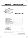
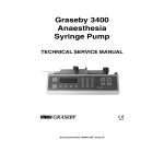
Trumpet curves
The curves were developed while testing the Model 3000/500 using
a Graseby Standard Adult Set, 8C-820 administration set.
The curves for the Micro 3100/505 are identical since both pumps
have the same pumping mechanism.
The trumpet curve represents the worst-case rate error in any given
observation window over the whole infusion period.
These trumpet curves were prepared according to the requirements
of IEC 601-2-24.
3000/3100 and 500/505 Service Manual
Issue A (April 2002)
2 — 9
2
Vo l u m e t r i c I n f u s i o n P u m p s
Graseby Medical Ltd.
2
2 — 10
Issue A (April 2002)
3000/3100 and 500/505 Service Manual
Overview of Pump
Operation
& Initial Checks
Chapter 3
Graseby Medical Ltd.
Vo l u m e t r i c I n f u s i o n P u m p s
Overview of Pump Operation & Initial Checks
This chapter provides an introduction to the Volumetric pump. It
gives an overview of:
The exterior of the pump (the revised case design is shown)
How the pump is powered
How the pump works
Power up - tests and checks
Powering down
Power monitoring and battery testing
Alarms and alerts.
3
The revised case design is shown on the diagrams on the next three
pages, but the keys, indicators and displays apply equally to the
original Volumetric case design.
Finding further information
Detailed information about the topics covered in this chapter may be
found later in this manual: Chapter 5 through Chapter 9.
The menus that allow the configuration of the pump are described in
Chapter 4.
Troubleshooting is described in Chapter 7 page 17.
Note: If you want to find out how to use the pump, you must read the
Instruction and Technical User Manuals. It contains not only
the full instructions, but also all the warnings and cautions that
must be followed for the safe use of the pump.
3000/3100 and 500/505 Service Manual
Issue A (April 2002)
3 — 1
Vo l u m e t r i c I n f u s i o n P u m p s
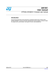
Exterior of the 500/3000 pump - front
Graseby Medical Ltd.
(Revised case design shown here)
Indicators and displays
3
*
Programming keys
*
* Bolus function available on
V0.71 software only
3 — 2
Issue A (April 2002)
3000/3100 and 500/505 Service Manual
Graseby Medical Ltd.
Vo l u m e t r i c I n f u s i o n P u m p s
Exterior of the pump - rear
(Revised case design shown here)
3
3000/3100 and 500/505 Service Manual
Issue A (April 2002)
3 — 3
Vo l u m e t r i c I n f u s i o n P u m p s
Graseby Medical Ltd.
How the pump is powered
The pump can be powered in two ways, either:
AC power connection
Battery operation, for backup, or portable operation.
AC power connection
The pumps are equipped with a detachable power cord, which has a
three-prong, hospital grade plug. The power cord is designed to
minimise leakage current inducing potentials on the ground wire.
3
The power cord is secured to the rear housing, but can be removed if
safety testing of the cord becomes necessary. A cord retainer is
attached over the cord by four screws. The cord retainer must be
reinstalled whenever the cord is reattached or replaced, or ground
and power connections may become unreliable.
If the cord is damaged, replace it immediately. Replacements should
be made using original equipment in order to maintain grounding
safety and an acceptable level of leakage current. Integrity of the
three-prong plug is also important to prevent electric shock. Do not
use extension cords, adapter plugs, or attempt to defeat the plugs
ground connection. Always hold the plug itself when unplugging the
power cord, as pulling on the cord could damage plug connections.
Battery and portable operation
The pumps contain a rechargeable 12 volt battery for portable
operation, or if AC power fails or is unavailable. Monitoring and
testing the battery is described on page 3-13.
The infusion pumps may be operated while standing on any flat
surface, provided the bottom of the administration set drip chamber
is at least 15 cm (6 inches) above the top of the pump.
On Model 3000/500, 30 cm (12 inches) may be required for rates over
500 mL/h. On both Model 500 and Micro 505, 30 cm (12 inches) may be
required when using thick solutions and/or 60 drops/mL sets.
Typically, however, the pump is attached to an IV pole using the pole
clamp on the rear housing. IV pole mounting and battery operation
make the pumps portable for patient mobility.
When multiple infusion lines are required, you can connect up to
three pumps to a single pole using the hooks and rails that make up
the modular connection system. As all pumps have connectors on both
sides, you can use any one as the centre, left, or right pump.
3 — 4
Issue A (April 2002)
3000/3100 and 500/505 Service Manual
Graseby Medical Ltd.
Vo l u m e t r i c I n f u s i o n P u m p s
How the pump works
This section provides a overview of how the pump works. Further
details are provided in Chapters 5 to 8.
For details of how to use the pump, refer to the Instruction Manual
and the Technical User Manual.
Microprocessors
The pumps contain a central system control microprocessor (CPU1),
with two peripheral microprocessors used for display control (CPU3)
and fail-safe system monitoring (CPU2). The central microprocessor
controls all user programmable functions, alarm condition sensors,
and inter-processor communications.
Pumping mechanism
The central microprocessor also controls a 4-phase stepping motor
which is used to operate the pumping mechanism. Smooth fluid
delivery is accomplished by uninterrupted forward rotation of the
pumping mechanism when the pump is running.
Door latch open
Pulling the door latch handle open moves the cam housing and
pumping mechanism to the load position. The pistons are best
positioned to accept a fluid filled cassette when in the load position.
When the door is opened to turn the pump on, or if the door is opened
while the pump is powering up, the hold light does not turn on until
the motor has backed off to its load position.
Door latch closed
Pushing the door latch closed moves the pumping mechanism to the
operate position.
Completion of cassette loading results in some additional reverse
rotation of the motor as pressure (which develops during the loading
process) on the cassette is reduced and the pumping mechanism
prepares for delivery. To allow up-line pressure release, the over
pressure valve seals the lower fluid pathway during reverse rotation
of the pumping mechanism and reopens upon initial forward rotation.
Free flow prevention system - safety clip
The Free-Flow Prevention System consists of the Safety Clip (located
under the cassette on the administration set) and the mechanical clip
retention slot and associated mechanics on the lower cassette
housing. The Safety Clip must be placed in the retention slot when
loading the cassette, or the pump will not operate.
When the door is closed the Safety Clip opens to allow fluid
delivery.
When the door is opened, the Safety Clip closes, preventing
unrestricted gravity flow even when the administration set is
removed from the pump.
3000/3100 and 500/505 Service Manual
Issue A (April 2002)
3 — 5
3
Vo l u m e t r i c I n f u s i o n P u m p s
Graseby Medical Ltd.
Pressure / occlusion monitoring
Downline pressure is developed by the pumping pistons at the upper
and middle cassette chambers, and is continuously monitored at the
middle cassette chamber.
Occlusion monitoring is performed by the pressure transducer
mounted in the door. The Occlusion alarm is activated if pressure
exceeds the user selected threshold level. The pump briefly backs off
to reduce downline pressure, which minimizes fluid bolus to the
patient. At that point, the pump stops and fluid delivery ceases.
3
Pumps with revision 0.64 and higher software
In the Medium or High Occlusion Alarm Settings, when downline
pressure exceeds the selected threshold, the motor pauses (Run
remains lit), and the pumping indicator stops. If, within 10 seconds,
the pressure drops back below the threshold, then pumping resumes
and no alarm is sounded (if pressure remains high, the Occlusion
below pump alarm is activated). If repeated pressure spikes occur,
causing the pump to enter the filtering process for a total of 30
seconds, measured over the last 4 minutes the pump was infusing, the
alarm also sounds. Occlusions detected in the Low Occlusion Alarm
Setting cause an immediate alarm.
Message Display
The Message Display is an alphanumeric liquid crystal display,
consisting of 2 lines by 16 characters. It shows infusion status, visual
alarms, options, and other messages.
When the pump is running, some messages are displayed briefly, then
the display reverts to the standard message. The general rule is:
informational messages are displayed for 5 seconds; messages with
instructions or which require input are displayed for 10 seconds.
Pressing a key which has a different display associated with it causes
its screen to be instantly displayed before the 5 or 10 second timeout
expires on the first message.
Numeric Displays
During operation, the rate and volume to be infused are continuously
shown in the numeric displays. The Message Display shows the
volume infused for the current infusion as fluid is delivered, and the
volume to be infused display counts down as the volume in the
Message Display counts up. Also, appropriate status lights are lit to
show the current status of the pump.
Numeric and Message Display Memory
When the pump is turned off, data in the Message Display and
numeric displays are stored in nonvolatile memory and displayed
again when the pump is turned on. The memory is maintained by a 3
volt lithium battery integrated with the memory chip.
3 — 6
Issue A (April 2002)
3000/3100 and 500/505 Service Manual
Graseby Medical Ltd.
Vo l u m e t r i c I n f u s i o n P u m p s
Backlight for Message Display
The Message Display is backlit when any key is pressed, and when
the door is opened. The backlight will remain on for approximately 1
minute. The backlight timeout feature has different characteristics
when the pump is on AC power and battery power.
Backlight on AC
With the pump on hold, and with the door closed, the backlight will
always be on. With the pump on hold, and with the door open, the
backlight will timeout after approximately 1 minute. After timeout, if
the door is closed, the Message Display backlight will turn on.
Backlight on Battery
When on battery power, the backlight will timeout after
approximately 1 minute whether the door is open or closed.
Backlight during an alarm or alert
During an alarm or alert, the backlight flashes on and off with the
audible alarms and remains on after the audio has been silenced.
Analog to digital monitoring
In addition to controlling the Message Display, numeric displays, and
LEDs, the display software monitors a number of analog to digital
conversion values. These are:
Pressure
Battery level
Cassette position
Ambient lighting level
LED/segment forward voltage drops. The LED/segment voltage
drops are checked during power-up.
Pressure, battery, light and cassette monitoring
A CPU periodically checks the current analog levels for the pressure
sensor input, the battery level, the pressure plate position input, and
the photo sensor used to measure ambient lighting. These levels are
each measured at least once per second, and their values (0-255) are
accessible to the on-board CPUs. Decisions based on sensor readings
require at least two reads of the sensor.
The pressure sensor input is used to check for occlusions.
The pressure plate position switch indicates whether the
cassette is in place.
The battery level input is used to check for low battery levels, or
when a battery test is initiated. Low battery levels result in
appropriate alarm messages.
The ambient lighting level input is used to adjust the intensity
of LEDs based on the current room lighting.
3000/3100 and 500/505 Service Manual
Issue A (April 2002)
3 — 7
3
Vo l u m e t r i c I n f u s i o n P u m p s
Graseby Medical Ltd.
LED/segment monitoring
The Display board CPU periodically (once per second) checks the
status of each individual LED and digit segment. If an LED or
segment should be off, it is checked to make sure there is no forward
voltage drop. If there is supposed to be a forward voltage drop and it
is absent, or it is outside the acceptable range a fault is reported to
the on-board CPUs and a System Error alarm message appears in the
Message Display.
3
3 — 8
Issue A (April 2002)
3000/3100 and 500/505 Service Manual
Graseby Medical Ltd.
Vo l u m e t r i c I n f u s i o n P u m p s
Power up tests and checks
This section explains the sequence of the pumps internal
initialisation tests and checks carried out on a Cold boot which takes
place if the On/Off key is pressed, or the door is opened whilst the
pump is switched off.
The end of this section describes what happens during a Warm boot,
which takes place if the microprocessor is reset when the pump is
already switched on.
Cold boot
When the pump is turned on, the cold boot sequence is as follows:
The I/O ports of the microprocessors are initialised, placing all
system components in the start up configuration.
A write/read back test is performed on non-volatile RAM. If this
test fails, the following message is displayed and the software is
locked allowing no further processing:
If the pump is plugged into AC power, the message remains until
the pump is unplugged. If being powered by the battery, the
message is displayed for 5 seconds, then the pump automatically
turns off.
A checksum comparison is performed on non-volatile RAM, and, if
it fails, system warning 13 is recorded for viewing in Biomedical
Special Functions. A memory location is then checked to
determine if the initialization was from a cold-boot or warm boot.
All CPU RAM locations are cleared.
The main CPU computes a checksum of its ROM contents and
compares this against a predetermined value. If a ROM checksum
error occurs, the following message is displayed, and the software
is locked allowing no further processing:
If the pump is plugged into AC power, the message remains until
the pump is unplugged. If being powered by the battery, the
message is displayed for 5 seconds, then the pump automatically
turns off.
Timers, counters, registers, and interrupts are initialised for
operation.
Counters and timers are initialised for pump history information.
A jumper wire is detected, thus determining whether the pump is
micro/macro (Model 500/3000) or micro only (Micro 505/3100).
3000/3100 and 500/505 Service Manual
Issue A (April 2002)
3 — 9
3
Vo l u m e t r i c I n f u s i o n P u m p s
Graseby Medical Ltd.
Communication is established between the CPUs. Commands are
exchanged signalling that initialization is completed and ROM
checksums are correct.
The keypad is scanned to determine whether Options was pressed
along with On/Off. If so, the pump enters Biomedical Menu.
The keypad is scanned to determine whether Silence was pressed
along with On/Off. If so, the pump activates Quiet Pump
operation.
A display test is run. The numeric displays illuminate the number
8 in each digit with decimal points active. While the numeric
displays are showing 8s, the pumping motion LEDs display the
number 8, then go blank. The message display briefly shows a
checker-board pattern.
3
The microprocessor checks to see if the pump is operating on AC
power or battery. If on AC power, the charge light is already lit. If
on battery power, the battery light illuminates, and the battery
voltage is checked to see if it is in operating range (> 11.6 V DC). If
the voltage is out of range (11.6 V DC), the low battery alarm
appears. See Power Monitoring, page 3-13.
The motor monitor microprocessor runs a motor cut-off test to
verify proper function of the motor driver shut off. If the motor
driver shut off is not working, a system warning is noted. Cold boot
stops, a snapshot is taken, and the following system warning is
displayed:
If the motor driver shut off is working, the cold boot continues and
the motor is backed off to its home position.
Primary parameters are retrieved from memory and displayed.
Secondary parameters are stored and ready for display. Secondary
volume to be infused defaults to zero and must be re-entered.
Successful completion of cold boot
A value is written in non-volatile memory as an indicator that a
cold boot process was completed.
The pump enters hold. Unless it was previously switched off in a
special infusion mode, for example, Rate Taper, or Dose-Rate
Calculation (recovery) mode, the standard message is displayed,
indicating that initialisation tests and checks are complete:
3 — 10
Issue A (April 2002)
3000/3100 and 500/505 Service Manual
Graseby Medical Ltd.
Vo l u m e t r i c I n f u s i o n P u m p s
End of cold boot - special infusion modes
If the pump was turned off in a special infusion mode, the standard
message is not displayed. Instead, the pump shows a screen
indicating the infusion mode, for example, with a Rate Taper program
set (but not delivered), the message display is:
If the pump was turned off during or after running a Rate Taper
program, the display will be:
If the pump was switched off after programming a Dose-Rate
Calculation infusion, and the Dose-Rate Calculation Recovery
parameter is enabled in the Technician Menu, then the display will
be:
Warm boot
A warm boot occurs if the microprocessor is reset when the pump is
already powered up. If a reset occurs the pump begins its power up
initialization routine. During the power up routine, the
microprocessor looks for a value in non-volatile memory normally
stored during the pumps power down routine. Since the normal
power down routine is not completed during a reset, the value is not
found and the current routine is considered a warm boot.
The rate display shows 0.1 and the volume to be infused display
shows 0.0 if a RAM checksum failure occurs.
If a warm boot occurs, the insistent audio alarm sounds, and a system
warning is displayed:
3000/3100 and 500/505 Service Manual
Issue A (April 2002)
3 — 11
3
Vo l u m e t r i c I n f u s i o n P u m p s
Graseby Medical Ltd.
Powering down
This section explains what happens when the pump is powered down
(switched off). It describes:
Manual power down, when the On/Off key is pressed
Automatic power down, which occurs when the pump has been left
on and alarming for 72 hours, or if the battery voltage becomes too
low.
3
Manual power down
The pump can only be turned off by pressing On/Off while the door is
closed. If the pump is running, you must first press Hold, then On/
Off.
The master CPU stops pumping operations and all system
components are disabled. The non-volatile memory is updated with
checksums. At this point, if the pump is on AC power, it will continue
to keep track of AC on time for pump history. The green charge light
is lit, indicating that the battery is charging. If powered by battery, a
non-volatile memory location is initialised, indicating power down
has occurred, after which the pump turns off.
If the pump is operating on battery power, and if the pump is stuck in
a fault mode where the CPUs are not operating properly, a special
command (OFFCPU2) allows On/Off to operate.
If the pump is connected to AC power, turned off, and the cord is then
unplugged, the pump powers down completely after writing data to
pump history.
Automatic power down
If the pump is left on hold (following an alarm, or if left idle) for
approximately 2 minutes with the door closed, the insistent audio
alarm sounds. If the pump is left on hold with the door open, the
pump alarms after approximately 6 minutes. In either case, if left
alarming for 72 hours, the pump automatically shuts off.
If the battery status in the Message Display indicates:
the pump enters hold (if running), sounds the insistent audio alarm,
and the hold light flashes. If left alarming, the pump will
automatically turn off in 15 minutes, or when the battery reduces to
10 volts.
3 — 12
Issue A (April 2002)
3000/3100 and 500/505 Service Manual
Graseby Medical Ltd.
Vo l u m e t r i c I n f u s i o n P u m p s
Power monitoring
On AC Mains
If the pump is plugged in, the charge light is steadily lit. Software
also records and stores in the pump history the period of time that
the pump is plugged in.
Note: If the pump is switched off and connnected to AC power and
the saftey keypad lockout feature is active, the pump cannot be
switched on via the keypad, see Instruction Manual, Security on the
pump.
On battery power
If there is a dropout in the voltage regulator due to AC line or
component failure, the pump automatically switches to battery
power. The battery light is steadily lit (unless the battery is low or
dead, in which case it flashes), the charge light is off, and the period
of time on battery is recorded and stored in the pump history.
Battery voltage levels are determined by:
Normal operating voltage:
Voltage > 11.6, ± 0.2 V DC.
Low battery:
11.0 < Voltage £ 11.6, ± 0.2 V DC.
Dead battery:
10.0 < Voltage £ 11.0, ± 0.2 V DC.
Automatic Turn Off:
Voltage < 10.0, ± 0.2 V DC.
Once a low battery state occurs (low battery, dead battery, or
automatic turn off) it remains in that state unless:
The pump is plugged in to AC power,
The voltage drops to a level consistent with another state, or
The pump is turned off, then on.
When the pump is turned on, on battery power, with Version 0.71
software loaded, the pump automatically carries out the battery test
described in the next section.
Testing the battery
When the pump is powered on, the battery is always tested. In
addition, the Options key provides access to the Battery Test option
so that the approximate battery voltage can be tested without
powering down the pump.
To run the Battery Test:
1. With the pump powered up, disconnect from the AC mains supply
and press Hold.
2. Press the Options key then 4, or press Options until the following
message is displayed:
3000/3100 and 500/505 Service Manual
Issue A (April 2002)
3 — 13
3
Vo l u m e t r i c I n f u s i o n P u m p s
Graseby Medical Ltd.
3. Press the
key to start the test. The pump turns on all LEDs,
and the rate and volume to be infused displays all zeros to form a
known battery load.
The pump then measures the battery voltage. After five seconds the
battery gauge displays the approximate battery capacity.
For example, this display would indicate a battery about half charged:
3
Each + indicates increasing battery voltage, as follows:
11.1
11.2
11.3
11.4
11.5
11.6
11.7
11.8
11.9
12.0
12.1
12.2
+
+
++
+++
++++
+++++
++++++
++++++++
+++++++++
++++++++++
+++++++++++++
++++++++++++++++
The display below indicates a fully charged battery:
If the battery capacity is low, you must connect the pump to the AC
mains supply to recharge the battery.
It is possible to get a false reading if the battery is in poor condition.
A new, fully charged battery operates the pump for approximately six
hours at 100 ml/hr (99.9 mL/h on Micro 505).
The test described above is also carried out automatically when a
pump loaded with Version 0.71 software (or later) is switched on, on
battery power.
WARNING:
3 — 14
Correct management of battery charging, as described in this
documentation is essential to ensure that the pump can operate
on battery for the time specified. Failure to do so may result in
compromised function of the product or patient injury.
Issue A (April 2002)
3000/3100 and 500/505 Service Manual
Graseby Medical Ltd.
Vo l u m e t r i c I n f u s i o n P u m p s
Alarms
This section explains the three different types of alarms made by the
pump.
insistent
non-insistent
continuous (backup alarm).
If more than one alarm condition exists simultaneously, insistent
alarms take precedence over non-insistent alarms.
When an alarm condition occurs, the red Hold light illuminates and
flashes at 1 Hz. The Message Display flashes with the alarm and an
error or alarm message is displayed.
When the audio alarm is silenced, the hold light stops flashing and
the Message Display remains lit with the alarm message displayed.
Software Version 0.67 and earlier
When a pump displaying the Battery too low - Plug in cord message
is connected to the AC mains supply, the unit will stop alarming, if
not previously stopped using the Silence or Hold key. The unit is on
Hold, and the Hold LED is on. However, the Message Display does
not show the On Hold message and the associated insistent alarm is
not sounded. To continue the infusion, the operator must press the
Run key.
Insistent alarm
This type of alarm indicates that fluid delivery has stopped, or cannot
be started.
The insistent audio alarm consists of three tones: two high pitched
and one low pitched, repeated at two-second intervals. (High/high/
low chime).
To silence an insistent alarm, press the Silence or Hold key. The
alarm will recur unless the problem is corrected.
If an insistent alarm condition is detected, the microprocessor stops
the pump and sounds the insistent audio alarm. One of the following
messages is displayed:
Air in cassette
Battery too low
Close clamp! Load Safety Clip
Door open
Loading problem. Check tubing set
No flow above pump
Occlusion below pump
On Hold
Secondary Complete
Preset limits exceeded.
3000/3100 and 500/505 Service Manual
Issue A (April 2002)
3 — 15
3
Vo l u m e t r i c I n f u s i o n P u m p s
Graseby Medical Ltd.
Non-insistent alarm
This type of alarm indicates that there is a condition requiring
attention which has not caused the infusion to stop. For example, if
the pump is running on batteries and the batteries are low, or if the
infusion has switched to a KVO rate.
The non-insistent audio alarm consists of two tones, one high pitched
and one low pitched, repeated at two second intervals. (High/low
chime.)
In KVO, the green run light flashes at 1 Hz with 50% duty cycle. In
low battery, the yellow battery light flashes at 1 Hz with 50% duty
cycle.
3
To silence this type of alarm, press the Silence or Run key to silence
the alarm without stopping fluid delivery, or press the Hold key to
silence the alarm and stop fluid delivery.
Detection of the following alert conditions cause the microprocessor
to sound the non-insistent audio alarm:
Dose setup not completed
Dose change not completed
Dose change not accepted
KVO xxx mL this infusion
Low battery. Plug in cord
Rate change not completed
Secondary was set.
Continuous - backup alarm
In addition to the insistent and non-insistent operational alarms, the
Volumetric pump has a fail-safe backup alarm system. This has a
distinctive high-pitched tone:
Should the audio alarm system fail, then the pump sounds the
backup alarm, with a 1.5 second pause between alarm tones;
Should an electromechanical system failure occur, the pump
sounds the backup alarm continuously.
The pump displays one of these messages when sounding the backup
alarm:
Pump needs service
System check. Turn off then on.
3 — 16
Issue A (April 2002)
3000/3100 and 500/505 Service Manual
Graseby Medical Ltd.
Vo l u m e t r i c I n f u s i o n P u m p s
Audio alarm specifications
The table below shows the specifications of the audio alarms. See
Biomedical Menu, page 4-26 for details on how to test these:
Name of alarm
Description
Frequency of chimes
High
Low
Insistent
high/high/low chime
every 2.25 seconds
3,000 Hz
2,200 Hz
Non-insistent
high/low chime
every 2.25 seconds
3,000 Hz
2,200 Hz
Back Up
high pitched
every 1.5 seconds
3,000 Hz
Continuous
high pitched
without pause
3,000 Hz
3000/3100 and 500/505 Service Manual
Issue A (April 2002)
3 — 17
3
Vo l u m e tri c P u mp Me n us
Chapter 4
Graseby Medical Ltd.
Vo l u m e t r i c I n f u s i o n P u m p s
Volumetric Pump Menus
Which version of software is in the pump?
This manual reflects the menus that are available in Version 0.71
software for the Volumetric pump. A pump has version 0.71 software
(or later) if:
The Secondary infusion key appears as:
The Instruction Label on the right hand side of the pump lists
more than eight options.
The Biomedical Model Number and Software Version menu (see
Biomedical Menu, page 4-11) shows V0.71, for example:
This manual also covers the Version 0.53, Versions 0.63, 0.65, and
0.67 software that may be installed in a Volumetric pump.
Introduction to menus
The menus are decribed in the following sections. However, for
detailed operating procedures refer to the Instruction Manual and
Technical User Manual.
The number of menus (some of which have overlap of features)
available on a pump varies depending on the software installed. The
full set of menus is as follows:
Technician
This menu is only present on pumps with version 0.71 software and
later. You use the Technician menu to enable the features of the
pump that have been introduced with version 0.71 software, as well
as enabling the features that existed in earlier versions.
Biomedical
Available in all software versions. In previous documentation it is
called the Biomedical Special Functions. As well as enabling or
disabling features, it displays data for fault finding and calibration.
Service Functions
Contains functions for servicing and setting the time in the pump.
Special Functions
Used to initialise the pump, for example after NV RAM or CPU board
replacements, or any software upgrades. Details of how to use the
Special Functions to initialise the pump vary with the software
version and are explained in Chapter 7, Troubleshooting section.
3000/3100 and 500/505 Service Manual
Issue A (April 2002)
4 — 1
4
Vo l u m e t r i c I n f u s i o n P u m p s
Graseby Medical Ltd.
About the Technician menu
This menu appears in version 0.71 software (or later). It allows you to
define how the pump behaves by setting values or by disabling or
enabling parameters.
Common parameters on Technician and Biomedical menus:
The common parameters on both the Technician and Biomedical
menus are Rate Taper, Volume Over Time and Dose Rate
Calculation.
Entering the Technician menu
To enter this menu, first switch off the pump if it is switched on.
Then press the Total Volume key while simultaneously pressing the
On/Off key. When you take your fingers off the keys, the pump
switches on and you are asked to enter the Technician menu ID.
4
Enter the numbers 0002.
As you enter the digits, asterisks (*) are displayed for security
protection. If you make a mistake, you must switch the pump off to
enter the correct ID. When prompted:
Enter the password 2020.
The password is always 2020, and cannot be changed.
Using the Technician menu
When you enter the Technician menu, the first parameter is the one
to enable or disable the display of the Pump Identifier. Move down
the list by pressing the Options key. Use the * key to toggle a
parameter. Thus if you see a screen like the following:
then the feature is disabled and you must press the * key to enable it.
You cannot move back through the menu. If you make a mistake, then
you can continue to move through the list by continuing to press the
Options key and the first item appears again when you reach the
end. You may find it faster to switch off and start again.
To move through the list quickly, and avoid going past the item you
want, you may also find it faster to count the number of times you
press the Options key. The table on the next page has been
numbered to help you do this.
Leaving the Technician menu
To exit from the menu, switch off the pump.
4— 2
Issue A (April 2002)
3000/3100 and 500/505 Service Manual
Graseby Medical Ltd.
Vo l u m e t r i c I n f u s i o n P u m p s
Summary of Technician menu parameters
The numbers on the left of this table show the number of Options key
presses to reach the parameter. The default settings are the factory
settings.
Configuration Parameter
Operation
Default
Pump Identifier
Enable or Disable
Disabled
1
Drug List
Enable or Disable
Disabled
2
Primary rate limits
Enable or Disable
Disabled
3
Primary Max VTBI
Enable or Disable
Disabled
4
Secondary/bolus rate limits
Enable or Disable
Disabled
5
Sec / Bolus Max VTBI
Enable or Disable
Disabled
6
KVO rate entry
Enable or Disable
Disabled
7
Occlusion Default
High, Medium or Low Medium
8
Secondary Stop
Enable or Disable
Disabled
9
Bolus
Enable or Disable
Disabled
10
Quick Rate
Enable or Disable
Enabled
11
Rate Taper
Enable or Disable
Enabled
12
Volume over Time
Enable or Disable
Enabled
13
Dose Rate Calculation (DRC)
Enable or Disable
Enabled
14
DRC Recovery
Enable or Disable
Disabled
15
Backlight
Enable or Disable
Enabled
16
Autolock Keypad
Enable or Disable
Disabled
17
GMT Timestamp
Enable or Disable
Enabled
18
Service Date
Review or Date Entry 00/00/00
19
Micrograms
Selection 1 (µg) or 2 (mcg)
3000/3100 and 500/505 Service Manual
Issue A (April 2002)
2
4 — 3
4
Vo l u m e t r i c I n f u s i o n P u m p s
Graseby Medical Ltd.
Using Technician parameters
Most parameters enable or disable features that appear when the
Options key is pressed. All only affect one feature, but for some you
may need to think about making another setting at the same time. For
example, if you enable Primary rate limits, you might also enable
Primary Max VTBI.
Pump Identifier
If you enable this parameter, when you press the Options key to
move to the next parameter you can edit the identifier text. When the
pump leaves the factory, this identifier is set to the serial number of
the pump. You can change the identifier character by character by
using the up and down keys (1 and 3) to cycle through alphanumeric
values. Press the * key to move to the next character. Press the
Options key when you are finished.
4
Note: Another separate identifier appears on the Special Functions Menu. This
also contains the pump serial number and will need to be reset to the serial
number if the pumps PCB is changed. See item 5 on page 4-30.
Drug list
Enabling this parameter gives the user the ability to choose a Drug
label from a preset list of drugs. If it is disabled, then the label is not
displayed.
Minimum and maximum primary rate
Enabling this parameter allows the user to define a range to limit the
Primary rate.
Maximum primary VTBI
Enabling this parameter allows the user to set the maximum volume
that can be infused for a Primary infusion.
Minimum and maximum secondary/bolus rate
Enabling this parameter allows the user to define a range to limit the
Secondary rate or bolus rate.
Maximum secondary/bolus VTBI
Enabling this parameter allows the user to set the maximum volume
that can be infused for a Secondary or Bolus infusion.
4— 4
Issue A (April 2002)
3000/3100 and 500/505 Service Manual
Graseby Medical Ltd.
Vo l u m e t r i c I n f u s i o n P u m p s
KVO rate entry
If this is enabled, then the user can set their own KVO rate. If it is
disabled, the default KVO rate (as shown in the specifications) is used.
Occlusion default setting
Use this option to set the occlusion default setting that should be
applied when the pump is switched on. Press * to change the default.
The user can press the Occlusion Alarm Setting key to change the
occlusion level for a particular infusion regardless of this default
parameter setting. However the default setting is reapplied when the
pump is switched off and on again.
Secondary stop
With this parameter enabled, the pump stops when a Secondary
infusion is completed. It sounds an insistent alarm and displays a
message to say that the secondary infusion is complete.
If Secondary stop is disabled, when a secondary infusion is complete,
the pump sounds a non-insistent alarm twice and then automatically
restarts the infusion at the primary rate.
This parameter is independent of the setting of the Bolus parameter
and only affects a Secondary infusion; at the end of a Bolus infusion
the pump always reverts to the previously programmed Primary rate.
Bolus
When this parameter is enabled, the user is given a choice of whether
a Secondary or a Bolus infusion is to be run when they press the
Secondary/Bolus key. If Bolus is chosen, the volume infused is
deducted from the Primary VTBI. If Secondary is chosen, the
Secondary volume infused is kept as a separate total and does not
affect the Primary VTBI.
If Bolus is disabled, the user is not given a choice when they press the
Secondary/Bolus key: they can only make settings for a Secondary
infusion.
Quick Rate Change
In software versions before 0.71, the Quick Rate Change parameter
was always enabled, and could not be disabled. From version 0.71, the
parameter may be enabled or disabled on the Technician Menu.
Enabling this feature allows users to use the Options key to put the
pump into a mode in which they can change the rate quickly while the
pump is running or on hold.
Rate Taper
Enabling this parameter allows the user to taper the infusion rate,
either up or down, for the administration of Total Parenteral Nutrition
(TPN), Total Parenteral Admixture (Three-in-One) or other applicable
therapies.
3000/3100 and 500/505 Service Manual
Issue A (April 2002)
4 — 5
4
Vo l u m e t r i c I n f u s i o n P u m p s
Graseby Medical Ltd.
Volume Over Time
Enabling this parameter allows the user to set up an infusion using
the volume to be infused and the total time, with the pump
automatically calculating the infusion rate. This can be done with
either Primary or Secondary infusions.
Dose-Rate Calculation
Enabling this parameter allows the user to set the dosing rate,
patient weight, the drug amount in the fluid bag and the volume in
the container, from which the pump then calculates the infusion rate.
Note: If you enable Dose-Rate Calculation, the Micrograms unit should also be
set (using the Micrograms parameter on this menu) according to your
hospitals protocol.
4
DRC Recovery
Enabling this feature allows a Dose-Rate Calculation mode infusion
to be accessed quickly when the pump is switched on.
Backlight
This parameter sets the default for how the backlight behaves when
the pump is switched on. With the parameter disabled, the backlight
will go off after a minute of keypad inactivity.
If the parameter is enabled, the user can use the Options key to
control whether the Message Display Light is permanently on or
behaves as described above when the option is disabled.
Autolock Keypad
With this parameter enabled, the keypad will automatically lock one
minute after a key was pressed.
The user can unlock the keypad by pressing twice on the Keypad
lock/unlock button on the back of the pump.
This is in addition to the manual keypad lock.
GMT Timestamp
Enabling this parameter displays the message GMT to the right of
the time display.
CAUTION:
4— 6
The backlight has a limited life and may, if used constantly, cause
the light to dim. Eventually the message display may then need
to be replaced. To preserve the life of the message display, you
should only allow the Message Display Light to be turned on as
described here if it is specifically required. Misuse of this feature
could lead to both battery and LCD depletion.
Issue A (April 2002)
3000/3100 and 500/505 Service Manual
Graseby Medical Ltd.
Vo l u m e t r i c I n f u s i o n P u m p s
Service Date
This parameter is used to set the service due date that is displayed
during power up when the pump is switched on. You can set or clear
the service date when this screen is displayed with the date flashing
on the Technician Menu:
Enter the new date in the format MM/DD/YY
To disable the Service Date feature, set the month, day and year to
zeroes.
When the pump is switched on, if the date set is reached or exceeded,
then an alarm is sounded and the following message is displayed:
to notify the user that the pump should be serviced.
Micrograms
Use this feature to determine the units to be displayed as µg or mcg
for the Dose-Rate Calculation. If you are not enabling Dose rate
calculation, you can ignore this item.
Note: Since the pump does not confirm the chosen unit display, test that the
display is set correctly. Switch the pump on normally and press the
Options key until the Message Display asks you to set the Dose-Rate
calculation. Then press * to examine the next screen.
3000/3100 and 500/505 Service Manual
Issue A (April 2002)
4 — 7
4
Vo l u m e t r i c I n f u s i o n P u m p s
Graseby Medical Ltd.
About the Biomedical menu
The Biomedical menu allows you to access technical information
about the pump and carry out adjustments and tests. In previous
documentation it has also been called the Biomedical Special
Functions
System faults
If a fault occurs while the pump is infusing on a ward, an error code is
recorded. An audio alarm sounds and the Message Display shows:
If the system error resulted from a temporary condition, turning the
pump off then on clears the alarm and allows you to continue the
infusion. However, if the above message persists, the pump must be
removed from the ward for service and repair.
4
Error codes resulting from system errors can be viewed in the
Message Display at a later time by entering the Biomedical menu and
perusing the menu parameters described overleaf. The pump defaults
to the screen displaying the error code.
Although the error codes are cleared when exiting the Biomedical
menu, they are stored as a snapshot event.
Entering the Biomedical menu
To enter this menu, first switch off the pump if it is switched on.
Press the Options key while simultaneously pressing the On/Off
key. When the keys are released, the pump switches on and you are
asked to enter the Biomedical menu ID.
Enter the numbers 3031.
As you enter the digits, asterisks (*) are displayed for security
protection. If you make a mistake, you must switch the pump off to
enter the correct ID. When prompted:
Enter the password 7867.
The password is always 7867, and cannot be changed.
Leaving the Biomedical menu
Switch off the pump to exit the menu.
Using the Biomedical menu - if no error has occurred
When you enter the Biomedical menu, the first screen you see
depends on whether an error has occurred while the pump was
running.
Navigate through the screens by pressing the Options key.
If no error has occurred, you go directly into Snapshot screen-a, see
page 4-10. To view further menu screens, press the Options key.
4— 8
Issue A (April 2002)
3000/3100 and 500/505 Service Manual
Graseby Medical Ltd.
Vo l u m e t r i c I n f u s i o n P u m p s
Using the Biomedical menu - after a fault has occurred
If you enter the menu after a fault has occurred, system errors and
warnings are displayed, for example:
When you switch off the pump to exit from the Biomedical menu, the
warning/error code is cleared but stored as a Snapshot event, see
page 4-11.
The table below shows the numbers that appear on the System Error
and System Warning screens.
Code
01
02
03
09
10
11
12
13*
14
15
16
17
19
20
21
22
23
24
25
28
30
31
32
33*
34
35
36
37
38
39
40
41
42
Error/warning
Power Fail (Battery) Detected.
Motor Monitor Communication time-out error.
Motor Monitor RAM error.
Motor Monitor Watchdog error.
CPU1 ROM Checksum error.
Motor Monitor Checksum error.
CPU1 RAM failure.
NV RAM checksum mismatch.
Main audio alarm Failure.
Motor fast error detected by Motor Monitor.
Motor slow error detected by Motor Monitor.
Motor disable test failure.
Air detect test failure.
No flow above pump circuit error.
Display board communications error.
Display digit error, 0-9.
Display LED error, 0-6.
Display Board ROM error.
Display Board RAM error.
Motor stall/interrupter.
Warm Boot.
Micro/Macro discrepancy error.
Pressure Plate Position Switch change during RUN.
Corrupted Triple Redundant variable in NV RAM.
LCD Display Failure.
Undefined Interrupt occurred.
Display field overflow error.
Display field parameter error.
Nonvolatile RAM battery low.
Stack overflow.
Pressure Plate Position Switch =1 when door is open.
Pressure >1 psi when door is open.
Safety clip in place when door is open.
Items 31 and 33 are system errors; all others are system warnings.
* See Faulty Component Identification in the Troubleshooting section
on page 7-17 for more details.
3000/3100 and 500/505 Service Manual
Issue A (April 2002)
4 — 9
4
Vo l u m e t r i c I n f u s i o n P u m p s
Graseby Medical Ltd.
Summary of Biomedical menu parameters
The numbers in the left hand column of this table indicate the
number of Options key presses to reach the parameter.
Screen
4
Use
Notes/see page ...
0
Two snapshot screens
are available: a and b.
Press * to toggle between
the two screens.
See About snapshot screens,
page 4-12.
1
Time and date display.
GMT shown if enabled on
the Technician menu.
See the Service Functions
Menu, page 4-23
2
The display shows:
See page 4-23.
cumulative running hours,
cumulative volume,
number of loading cycles.
3
Cumulative hours that the See page 4-23.
pump has been:
used on AC mains whilst
switched on,
charging: plugged in but
switched off,
used on batteries.
4
Allows you to run a
calibration test.
See page 4-24.
5
Shows the current rate
setting of the serial port.
Rates of 300, 600, 1200, 2400 and
are available. See page 4-25.
6
Displays the language
installed in the pump.
Only one language is
supplied in a pump.
7
Displays the number of
times a pump was used
on battery for the number
of hours indicated.
Use the scroll keys (1 and 3)
to change the displayed
number of hours.
See page 4-25.
8
Displays the model
number and software
revision.
See page 4-26.
9
Use this screen to test
the alarms by pressing
1, 2 and 3 on the keypad
See page 4-26.
10 Rate Taper
Enable or Disable.
See Technician menu.
11 Volume Over Time
Enable or Disable.
See Technician menu.
12 Dose Rate Calculation
Enable or Disable.
See Technician menu.
4— 10
Issue A (April 2002)
3000/3100 and 500/505 Service Manual
Graseby Medical Ltd.
Vo l u m e t r i c I n f u s i o n P u m p s
About Snapshot screens
Two Snapshot screens contain detailed information about the
operation of the pump. Snapshot screen-a contains the first level of
detail about an event, snapshot screen-b contains further details.
The information on the snapshot screens is encoded, in order to
present a large amount of detail on the display area. This section
describes the snapshot screens, and explains how to decode the
information that they contain.
The pump stores 200 events (50 on a pre-version .63 pump). For each
event, there is a snapshot screen-a and associated snapshot screen-b.
Using PC history software to interpret snapshot screens
A Graseby Medical History Download Software Kit is available. This
enables you to view, log, store and print out the encoded information
in an easy-to-read format, rather than carry out the manual decoding
described here.
To display Snapshot Screen-a
If no error message has occurred on the pump immediately before you
access the Biomedical Menu, then the first item displayed on the
Biomedical Menu is Snapshot screen-a, showing event number 1. For
details, see Decoding Snapshot screen-a, on page 4-12.
To display Snapshot Screen-b
When Snapshot screen-a is displayed, you can change the display to
show the associated Snapshot screen-b:
Press *.
To move back to Snapshot screen-a, press * again.
For details, see Decoding Snapshot screen-b, on page 4-15.
To display snapshots of next or previous events
t keys. For
To see snapshots of other events, use the 3▲ and 1
example:
t to go to event 200 (or
On event 1, press 3▲ to see event 2. Press 1
50 on a pre-version 0.63 pump).
t to go to event 199 (49) or press 3▲ to go to
On event 200 (50) press 1
event 1.
To show the next parameter
To move from the snapshot screens and show the next parameter
(time and date display), press Options. Press Options repeatedly to
move through all the parameters. A description of the Biomedical
Menu parameters starts on page 4-23.
3000/3100 and 500/505 Service Manual
Issue A (April 2002)
4 — 11
4
Vo l u m e t r i c I n f u s i o n P u m p s
Graseby Medical Ltd.
Decoding Snapshot screen-a
Snapshot screen-a contains information in these fields, explained in
the table below:
This is an example of values in fields in Snapshot screen-a, shown in
the right hand column of the table below:
4
Top row of snapshot screen-a:
Field
Contains
Values/range
Example shows
###
Event number
1 is most recent event
In range 1 - 200
or 1 - 50 for preversion 0.63 pumps
Event number 26
MMDD
Month and day
Month 1 - 12,
day 1-31
May 9th
HRMM
Hour and minute
Hour 0 - 23,
minute 0 - 59
11:45
ZZ
System state code
0 - 99 - see table
on page 4-13
State code 19
air detector
Bottom row of snapshot screen-a:
Field
Contains
Values/range
Example shows
RATE
Rate
0 - 999.0 mL/hr*
on model 500/3000.
0 - 99.9 mL/hr *
on micro 505/3100
350.0 mL/hr
VTOBI
Volume to be infused
at the time of the
snapshot
0 - 9999.0 mL*
on model 500/3000.
0 - 999.9 mL*
on micro 505/3100
1400.0 mL
VOLUM
Total volume infused
this infusion
0 - 9999.0 mL*
on model 500/3000
0 - 999.9 mL*
on micro 505/3100
100.0 mL
* Implied decimal point, not displayed:
rightmost digit is in 10ths mL
4— 12
Issue A (April 2002)
3000/3100 and 500/505 Service Manual
Graseby Medical Ltd.
Vo l u m e t r i c I n f u s i o n P u m p s
Snapshot screen-a - system state codes
This list shows the possible system/state codes shown on the top right
hand line of a Snapshot screen-a:
This is the system
state code
Code
00
01
02
03
09
10
11
12
13*
14
15
16
17
19
20
21
22
23
24
25
28
30
31
32
33*
34
35
36
37
38
39
40
41
42
Meaning
No action, initialization value.
Power Fail (Battery) Detected.
Motor Monitor Communication time-out error.
Motor Monitor RAM error.
Motor Monitor Watchdog error.
CPU1 ROM Checksum error.
Motor Monitor Checksum error.
CPU1 RAM failure.
NV RAM checksum mismatch.
Main audio alarm Failure.
Motor fast error detected by Motor Monitor.
Motor slow error detected by Motor Monitor.
Motor disable test failure.
Air detect test failure.
No flow above pump circuit error - return pump to SIMS
Graseby or Service centre.
Display board communications error.
Display digit error, 0-9.
Display LED error, 0-6.
Display Board ROM error.
Display Board RAM error.
Motor stall/interrupter.
Warm Boot.
Micro/Macro discrepancy error.
Pressure Plate Position Switch change during RUN.
Corrupted Triple Redundant variable in NV RAM.
LCD Display Failure.
Undefined Interrupt occurred.
Display field overflow error.
Display field parameter error.
Nonvolatile RAM battery low.
Stack overflow.
Pressure Plate Position Switch =1 when door is open.
Pressure >1 psi when door is open.
Safety clip in place when door is open.
list continues ...
* see Faulty Component Identification in the Troubleshooting section on page 7-17
3000/3100 and 500/505 Service Manual
Issue A (April 2002)
4 — 13
4
Vo l u m e t r i c I n f u s i o n P u m p s
Graseby Medical Ltd.
System state codes, continued
Code
43
44
45
62
63
64
65
66
67
68
69
70
71
72
73
74
75
76
77
78
79
80
81
82
83
84
85
86
87
88
89
90
91
92
93
94
95
96
97
98
4
99
4— 14
Meaning
Service Due Alarm.
Secondary Stop Alarm
Preset Limits Exceeded Alarm.
Computer Interface Event.
Time Change Event.
On HOLD Alarm.
Stop pumping - Occlusion.
Stop pumping - Air.
Stop pumping - No flow above pump.
Stop pumping - Door Open.
Stop pumping - Loading problem, Pressure Plate.
Status of pump - Low Battery (11.0 < = voltage < 11.6).
Stop pumping - Dead Battery (voltage < 11.0 volts).
Stop pumping - Safety Clip.
Change rate to KVO.
Running rate change not completed.
On battery (loss of main power).
Start pumping using RUN key.
Stop pumping using HOLD key.
Secondary to primary switch.
Occlusion Alarm Setting change to low.
Occlusion Alarm Setting change to medium.
Occlusion Alarm Setting change to high.
Running rate change.
rate change.
Taper to new rate.
Power down.
Pump on Battery.
Turn off AC.
Turn on AC.
Motor reverse stall.
Power change - battery to AC.
Dose change not completed.
Dose change not accepted.
Dose-Rate Calculation setup.
Dose field overflow.
Volume Over Time setup.
Dose-Rate Calculation setup not completed.
Door has been opened.
Pause pumping - excess pressure detected (software
revision 0.64 and higher).
Resume pumping - pressure reduced (software revision
0.64 and higher).
Issue A (April 2002)
3000/3100 and 500/505 Service Manual
Graseby Medical Ltd.
Vo l u m e t r i c I n f u s i o n P u m p s
Decoding Snapshot screen-b
On Snapshot screen-a, press * to display Snapshot screen-b.
This is an example of Snapshot screen-b:
Snapshot-b contains information in eight fields, explained in the table
below. You would normally use the PC utility to interpret these
fields.
Note: Fields are all decimal numbers in the range 0-255
The contents of GGG depend on the value of the System state code (ZZ)
on Snapshot screen-a.
Field
Contains
Action and Detail Chart Ref.
###
Event number
1 is most recent event
AAA
Pumps main modes
Convert decimal to binary
then use Chart A
BBB
Pumps state modes
Convert decimal to binary
then use Chart B
CCC
Pumps physical modes
Convert decimal to binary
then use Chart C
DDD
Pumps sensor flags
and status of the pumps
occlusion alarm setting
Convert decimal to binary
then use Chart D
Occlusion alarm setting see
bits 4 and 5 and use Chart D-D
EEE
Keyboard state input mode
Use Chart E
FFF
Battery voltage at time
of snapshot, shown as
the average of the last two
analog-to-digital readings.
Use Chart F
GGG
(all System state
codes except for
33, 35 or 93)
Pumping pressure at time
Carry out calculation to
of snapshot: average
compute the pumping pressure
pressure reading of the last
as described in Chart G
two analog-to-digital readings.
3000/3100 and 500/505 Service Manual
Issue A (April 2002)
4 — 15
4
Vo l u m e t r i c I n f u s i o n P u m p s
Field
Graseby Medical Ltd.
Contains
Action
GGG state code 33
Identifier for the Corrupted
Triple Redundant variable
in NV RAM
Use Chart G - State Code 33
GGG state code 35
Identifier for the Undefined
Interrupt
Use Chart G - State Code 35
GGG state code 93
Dose-Rate Calculation dose
mode and amount mode
selected
Convert to hexadecimal then
use Chart G - State Code 93
4
Converting Snapshot screen-b values from decimal to binary
This section does not explain the process of conversion, but shows the
conversion of the fields on this sample Snapshot screen-b.
Fields A, B C and D on snapshot screen-b need to be converted into a
binary format. If you do not have access to the History Download
Software Kit for decoding snapshot screens (see page 4-11), you can
use the examples in this section to remind yourself how to convert a
decimal number to its binary equivalent.
The numbers on the screen above are explained in the table below:
The top heading line shows how the bits are numbered, with bit
zero on the right.
The next heading line, in italics, shows the value that is assigned
to each of the 8 bits.
Each detail line shows the decimal value taken from the example
screen in bold, and shows how each of the the bits are set to
represent that decimal value (0 is off, 1 is on).
For example, AAA has a decimal value of 72, so bit 6 (value 64) is
set, and bit 3 (value 8) is set:
4— 16
Bit number
7
Binary digit value
Field AAA
5
4
3
2
1
0
128 64
32
16
8
4
2
1
072
0
1
0
0
1
0
0
0
Field BBB
004
0
0
0
0
0
1
0
0
Field CCC
029
0
0
0
1
1
1
0
1
Field DDD 139
1
0
0
0
1
0
1
1
Issue A (April 2002)
6
3000/3100 and 500/505 Service Manual
Graseby Medical Ltd.
Vo l u m e t r i c I n f u s i o n P u m p s
Chart A Pump Main Modes
Once you have converted the decimal value in field AAA into binary
format, use this chart to find out the pumps state modes. The
example of Snapshot-b shows field AAAs value as 072 (decimal),
which converts into 01001000.
Bit 7
Bit 6
Bit 5
0=
Not used
Unit not
in doserate calc
1=
Not used
Unit is in
dose-rate
calc.
Bit 4
Bit 3
Bit 2
Bit 1
Bit 0
Unit not
Unit not
in quick
in dead
rate change battery
condition
Unit not
in low
battery
condition
Unit not
in KVO
Unit is in
primary
Unit not
running
Unit is in
quick rate
change
Unit is in Unit is in
low battery KVO
condition
Unit is in
secondary
Unit is
running
Unit is in
dead
battery
condition
4
Chart B Pump State Modes
This chart shows the state modes that can be decoded from field BBB
on Snapshot-b when the value is converted to binary. The example of
Snapshot-b shows a value of 004 (decimal) which converts into
00000100.
Bit 7
Bit 6
Bit 5
Bit 4
Bit 3
Bit 2
Bit 1
Bit 0
Pump not
in rate
taper end
early
Pump not
in rate
taper
0 = Primary/
secondary
rate/volume
not decimal
since total
volume last
cleared
Secondary Secondary
VTBI does rate does
not have
not have
decimal
decimal
place
place
Primary
Primary
VTBI does rate does
not have
not have
decimal
decimal
place
place
Standard
message
not in
message
display
1= Primary/
Secondary
rate/volume
was decimal
since total
volume last
cleared
Secondary
VTBI has
decimal
place
Primary
VTBI has
decimal
place
Standard
Pump is in Pump is in
message is rate taper rate taper
in message end early
display
Secondary
rate has
decimal
place
Primary
rate has
decimal
place
Chart C Pump Physical Modes
Convert the value in CCC to binary then use this table to decode the
bits. In the example screen, the decimal value is 029, or binary
00011101.
Bit 7
Bit 6
Bit 5
Bit 4
0=
Not used
Run not
pending
Not used
Cassette not
in position
Not used Safety clip
not in place
Door not
open
1=
Not used
Run
pending
Not used
Cassette in
position
Not used Safety clip
in place
Door open Pump
turned on
3000/3100 and 500/505 Service Manual
Bit 3
Bit 2
Issue A (April 2002)
Bit 1
Bit 0
Pump not
turned on
4 — 17
Vo l u m e t r i c I n f u s i o n P u m p s
Chart D
Graseby Medical Ltd.
Pump sensor flags and occlusion alarm setting
Once you have converted the decimal value into binary format, use
this chart to determine the pumps sensor flags and status of the
pumps occlusion alarm setting. In the example Snapshot screen-b,
field DDD shows a value of 139 decimal. This converts to 10001011 in
binary format.
Bit 7
Bit 6
Bit 5 and Bit 4
Bit 3
Bit 2
Bit 1
0=
Micro
jumper
Not
Used
Occlusion alarm status
- see Chart DD below
Auxilliary
power off
CTS not
active
Keypad
Pump on
not locked AC
1=
No Micro
jumper
Auxilliary
power off
CTS
active
Keypad
locked
4
Bit 0
Pump
on battery
Chart DD - Occlusion alarm status
Use this table to determine the occlusion alarm status from bits
5 and 4 of the binary representation of field DDD.
Bit 5
Bit 4
0
0
1
1
0
1
0
1
Occlusion alarm setting
Undefined
Low
Medium
High
Chart E - Keypad State Input Mode
Use this chart to determine the keypad state input mode. Do not
convert to binary. Take the value from field EEE on Snapshot screen-b.
Value
Mode
0
1
2
3
4
5
6
7
8
9
10
11
12
13
14
15
Keypad default mode.
Occlusion Alarm Setting.
Options.
Quick Rate Change.
Total Volume.
Taper End Early.
Taper setup.
Keypad Locked.
Rate input.
Volume to be Infused input.
Taper Run.
Volume Over Time setup.
Dose-Rate Calculation setup.
Dose Run.
Dose-Rate rate titrate.
Dose-Rate dose titrate.
The example snapshot screen-b shows field EEE with a value of
decimal 008, so the keypad state input mode is Rate input.
4— 18
Issue A (April 2002)
3000/3100 and 500/505 Service Manual
Graseby Medical Ltd.
Vo l u m e t r i c I n f u s i o n P u m p s
Chart F - Battery Voltage
Use this chart to convert the average value of the last two analog-todigital readings into the battery voltage at time of snapshot. Take the
value from field FFF on Snapshotscreen-b.
Analog-to-Digital
Value
Voltage
186
188
190
191
193
195
197
199
200
202
204
205
11.1
11.2
11.3
11.4
11.5
11.6
11.7
11.8
11.9
12.0
12.1
12.2
4
Analog-to-digital values that fall between those listed in the table
may be interpolated to determine the voltage.
For example, the example snapshot screen-b shows the value as
decimal 194, so the voltage value is 11.55.
Chart G - Pumping pressure
Use this section to interpret field GGG on snapshot screen-b for all
system state codes except 33, 35 or 93 which are described later in
this chapter. This example shows field GGG with a value of 131.
These instructions explain how to compute the pumping pressure of
the pump at the time of the snapshot.
The pressure sensor has a zero offset Analog-to-Digital value of 0 to 3.
In addition to that, every increment of 21 represents 1 psi.
Use the following steps to compute the pumping pressure contained
in field GGG on Snapshot-b:
1. Take the decimal value in GGG and subtract 5.
2. Divide the result by 21 to give the pressure in psi.
These steps can be represented by the formula:
(GGG-5) / 21 = n psi
As an example of how the formula works:
If the value of GGG is 131:
3000/3100 and 500/505 Service Manual
(131-5) / 21 = 6 psi
Issue A (April 2002)
4 — 19
Vo l u m e t r i c I n f u s i o n P u m p s
Graseby Medical Ltd.
Chart G - State Code 33 - Corrupted Triple Redundant variable in NV RAM
If the system state code on screen-a is 33, find the identifier of the
corrupted variable by checking the value of GGG on screen-b:
4
GGG
Variable Identifier
0
1
2
3
4
5
6
7
8
9
10
11
12
13
14
15
16
17
18
19
Micro/Macro flag
Rate calibration factor
Pressure search limit
Back off pressure
Language select
Baud rate
Pump serial number
Pump enabled for Volume Over Time
Pump enabled for Dose-Rate Calculation
Rate Taper enable flag
Volume Over Time enable flag
Dose-Rate Calculation enable flag
Alternate search pressure
Alternate search rate
Search occlusion pressure
Back off range low
Back off range high
Serial key flags
Back off method
Long search half step limit
Chart G - State Code 35 - Undefined interrupt
If the system state code on screen-a is 35, find the cause of the
undefined interrupt by checking the value of GGG on screen-b:
4— 20
GGG
Interrupt Identifier
0
1
2
3
4
5
6
7
8
9
10
11
12
13
14
15
16
17
18
19
20
Reset
Clock monitor
Cop watchdog
Bad opcode
Software interrupt (SWI)
Non-maskable interrupt (XIRQ)
Hardware interrupt (IRQ)
Real time interrupt
Timer input capture 1
Timer input capture 2
Timer input capture 3
Timer output compare 1
Timer output compare 2
Timer output compare 3
Timer output compare 4
Timer output compare 5
Timer overflow
Pulse accumulator overflow
Pulse accumulator input edge
Serial Peripheral Interface
Serial Communications Interface
Issue A (April 2002)
3000/3100 and 500/505 Service Manual
Graseby Medical Ltd.
Vo l u m e t r i c I n f u s i o n P u m p s
Chart G - State Code 93
If the system state code (ZZ) on Snapshot screen-a is 93, then GGG on
snapshot screen-b contains a decimal representation of a hexadecimal
value. This hex value encodes the amount mode and dosing mode
selected by the operator during a Dose-Rate Calculation program
setup.
If the system state code is 93 use the instrucitons in this section to
convert the value to hexadecimal and then interpret the result using
the table below.
To convert the GGG value:
1. Take the decimal number, and divide it by 16.
2. The initial quotient is digit 1 and the remainder is digit 0.
4
As an example, if the value of GGG was 052:
052 / 16 = 3 (digit 1), with a remainder of 4 (digit 0).
To interpret the result
Look up the resulting values for digit 1 and digit 0 in the table below
to find out the dosing mode and amount mode:
Digit 1 - Amount mode
0
1
2
3
MG/bag
Gm/bag
mcg/bag
units/bag
Digit 0 - Dosing mode
0
1
2
3
4
5
6
7
8
mcg/kg/min
mcg/min
MG/min
MG/hr
units/hr
MG/kg/hr
mch/kg/hr
MG/kg/min
units/kg/hr
In the example above:
Digit 1 with a value of 3 indicates an Amount mode of units/bag
Digit 2 with a value of 4 indicates a Dosing mode of units/hr.
3000/3100 and 500/505 Service Manual
Issue A (April 2002)
4 — 21
Vo l u m e t r i c I n f u s i o n P u m p s
Graseby Medical Ltd.
Using Biomedical Parameters
This section explains how to use the Biomedical Menu parameters,
summarised on page 4-10. To find out about the snapshot screens and
how to decode them, see page 4-11.
Press the Options key to navigate from one parameter to the next.
You cannot move backwards; to redisplay a parameter, press the
Options key repeatedly to move through all the parameters until you
see the one you require.
Time and date display
4
The first line displays the time in the format hh:mm:ss.
GMT is only displayed if it has been enabled on the Technician menu,
see page 4-6.
The second line displays the date in the format mm/dd/yy.
To change the date or time, use the Service Functions menu
described on page 4-29.
Pump history display
This parameter shows a summary of the statistics for pump usage. It
shows:
4— 22
Hrs: cumulative hours that the pump motor has been running.
The number of hours can range from 0 to 99999. This example
shows that the pump has been running for 19 hours.
Liters: cumulative volume infused, in liters. The volume
infused ranges from 0 to 99,999 litres. The volume shown in the
example above is 9 litres.
Load: number of loading cycles - the number of times that the
door has been opened. The value is in the range 0 to 99999. The
example above shows 22 load cycles.
Issue A (April 2002)
3000/3100 and 500/505 Service Manual
Graseby Medical Ltd.
Vo l u m e t r i c I n f u s i o n P u m p s
Charge History
This parameter shows a summary of the pumps charging history. It
shows:
AC: total number of hours that the pump has been turned on
whilst plugged into the AC mains supply. The hours can range
from 0 to 99999. This example shows 18 hours.
Charge: AC charge time. This is the accumulation of time the
pump is plugged in and turned off. Range from 0 to 99999. For
software versions 0.67 this accumulation is updated provided
the pump is turned on before being unplugged. For software
versions 0.71 the pump will log the time it is plugged into the
AC and not switched on as Charge Time, regardless of whether
the pump was switched ON before AC was removed. The
example shows AC charge time of 73 hours.
Batt: total number of hours the pump has been turned on and
powered by battery, i.e. not plugged in. The example shows 2.
The total number of hours that the pump has been switched on
(cumulative hours of operation) is the sum of AC and Batt hours, in
this example, 20 hours.
Pressure display parameter (on battery power)
You can only calibrate the pressure transducer on the front door
assembly sensor of the pump when the pump is connected to the AC
mains supply.
If the pump is operating on battery power, the pressure calibration
mode parameter is not shown. Instead, you see the screen:
If you connect the pump to the AC mains supply while this screen is
shown, the pressure calibration mode screen will appear, as shown
over the page.
3000/3100 and 500/505 Service Manual
Issue A (April 2002)
4 — 23
4
Vo l u m e t r i c I n f u s i o n P u m p s
Graseby Medical Ltd.
Pressure display - calibration mode
If the pump is operating on AC mains supply, the pressure
transducer on the front door assembly sensor may be calibrated, so
you see this parameter:
A
B
C D
The bottom line of this screen shows four fields, marked on the above
example as A, B, C and D. They are described in the table below:
Field
Range
Comment
A
0 to 1919
unref
or *
Represents motor position. It shows unref if
the motor cam position is unreferenced. It shows
* in the first position if a motor stall was detected.
B
0 to 1919
Represents the position immediately before the
last motor home position realignment. If there is
no significant motor slippage, expected display
values are between 0 and 40 or 1880 and 1919.
C
0 to 255
Raw analog-to-digital pressure reading from the
display board. This value is read and the Message
Display value updated at least twice per second.
This permits occlusion alarm calibration to a
known pressure by adjusting two potentiometers,
see Occlusion alarm adjustment on page 8-15..
D
1, 0 or -
Represents the pressure plate position
switch, where:
1 = cassette-in-position
0 = no cassette present
- = communication error when switch
is read.
4
Pressure transducer calibration screen
The default rate is 25 mL/h. To adjust the rate:
Press Rate and enter a rate with the number keys. The run light
flashes whenever a rate can be entered using number keys.
To accept the entered rate:
Press Run. The rate appears in the rate display.
To toggle the motor direction:
Press Primary. If the motor is running backwards, the pumping
indicator shows a minus sign. If the motor is running (forward or
backward) the run light is continuously lit.
To stop the motor.
Press Hold. When the motor stops the hold light is lit.
4— 24
Issue A (April 2002)
3000/3100 and 500/505 Service Manual
Graseby Medical Ltd.
Vo l u m e t r i c I n f u s i o n P u m p s
Baud rate
This screen displays the current baud rate selection for the computer
port: 300, 600, 1200, 2400, 4800, or 9600. The default baud rate is 9600
baud.
Press 1 ( ) or 3 ( ) to display the next or previous baud rate.
If you press 1 ( ) when 300 baud is shown, the display changes to
9600. If you press 3 ( ) when 9600 baud is displayed, the display
changes to 300.
Press Options or On/Off to accept the last baud rate shown.
4
Language
This screen displays the language currently in the pump's software.
The above example shows English, but the pump may show any one of
the following:
English
French
German
Dutch
Swedish Japanese
Italian
Spanish
Portuguese
Only one language is supplied in any one pump. Contact Graseby
Medical to determine language availability. Pressing 1 ( ) or 3 ( ) will
not change the language selection.
Battery use
The pump records information about the number of times it is used
on battery. It records the information against the period of time for
which it was used.
For example, the screen above shows Battery use 0 - 1 hr: 42,
indicating that the pump has been used 42 times for one hour or less.
Use 1 ( ) or 3 ( ) to see how many times the pump has been used on
battery for the other periods of time:
0-1
1-2
2-3
3-4
hours
hours
hours
hours
4-5 hours
5-6 hours
6-7 hours
7+ hours
The maximum number of hours that can be shown is 99999.
3000/3100 and 500/505 Service Manual
Issue A (April 2002)
4 — 25
Vo l u m e t r i c I n f u s i o n P u m p s
Graseby Medical Ltd.
Model number and software version
The model number and software version parameter contains
information in these fields, explained in the table below:
This is an example of the screen:
The values in this example are shown in the right hand column of the
table below.
Field
4
Contains
Example
XXXXX
Model number: 3000 or 3100
(In the U.K. only, the Volumetric Infusion
Pumps are called 500 and 505.)
3000
VY.YY
Software version resident in the
ROM of the main processor
0.71
DB:Z.ZZz
Software version resident in the
Display Board microprocessor
3.65A
MM:G.GG Software version resident in the
Motor Monitor microprocessor
1.10
The lower case z in the above screen is always present on Dose-Rate
pumps. It signifies the language selected.
It is only present when a language other than English was selected on
non Dose-Rate pumps.
Audio alarm test
This screen allows you to verify proper operation of the audio alarms
by pressing a key to sound each type of alarm:
Press 1 to initiate a non-insistent alarm
Press 2 to initiate an insistent alarm
Press 3 to initiate a backup audio alarm
Press any other key to stop the alarm.
The hardware which produces the Back Up audio alarm is the same
as that used by the Continuous alarm.
4— 26
Issue A (April 2002)
3000/3100 and 500/505 Service Manual
Graseby Medical Ltd.
Vo l u m e t r i c I n f u s i o n P u m p s
Audio alarm specifications
The table below shows the specifications of the audio alarms:
Type of alarm
Repetitions
Frequency of chimes
High
Low
Insistent
high/high/low chime
every 2.25 seconds.
3,000Hz
2,200Hz
Non-insistent
high/low chime
every 2.25 seconds.
3,000Hz
2,200Hz
Back Up
high pitched
every 1.5 second.
3,000 Hz
Continuous
high pitched
without pause.
3,000 Hz
4
Enabling special programming functions
In software versions before version 0.71, the Rate Taper, Volume over
Time and Dose-Rate Calculation pump programming modes could
only be enabled or disabled on the Biomedical Menu of Dose-Rate
pumps.
From version 0.71, these parameters appear on the Technician Menu
described on page 4-2, as well as on the Biomedical Menu.
It is recommended that you should place an external label on a pump
to indicate which functions have been enabled.
Enable/disable rate taper
Enabling this parameter allows the user to taper the infusion rate,
either up or down, for the administration of Total Parenteral Nutrition
(TPN), Total Parenteral Admixture (Three-in-One) or other applicable
therapies.
Use the * key to toggle this parameter. Thus if you see a screen like
the following:
then the rate taper is enabled and you must press the * key to disable
it.
If you press *, the screen changes to:
Press the * key again to re-enable the Rate Taper mode.
3000/3100 and 500/505 Service Manual
Issue A (April 2002)
4 — 27
Vo l u m e t r i c I n f u s i o n P u m p s
Graseby Medical Ltd.
Enable/disable volume over time
Enabling this parameter allows the user to set up an infusion using
the volume to be infused and the total time, with the pump
automatically calculating the infusion rate. This can be done with
either Primary or Secondary infusions.
Use the * key to toggle this parameter, as described for Enable/
Disable Rate Taper, on page 4-27.
Enable/disable dose-rate calculation
Enabling this parameter allows the user to set the dosing rate,
patient weight, the drug amount in the fluid bag and the volume in
the container, from which the pump then calculates the infusion rate.
If you enable Dose-Rate Calculation, the Micrograms unit should also
be set (using the Micrograms parameter on the Technician Menu, see
page 4-5) according to your protocol.
4
Use the * key to toggle this parameter, as described for Enable/
Disable Rate Taper, on page 4-27.
4— 28
Issue A (April 2002)
3000/3100 and 500/505 Service Manual
Graseby Medical Ltd.
Vo l u m e t r i c I n f u s i o n P u m p s
About the Service Functions menu
The Service Functions menu allows you to set the date and time on
the pump and to test some pump functions.
Entering the Service Functions menu
To enter this menu, first switch off the pump if it is switched on.
Then, press the Occlusion Alarm Setting key while simultaneously
pressing the On/Off key. When you take your fingers off the keys, the
pump switches on and you are asked to enter the Service Function
menu ID.
Enter the numbers 7557.
As you enter the digits asterisks (*) are displayed for security
protection. If you make a mistake, you must switch the pump off to
enter the correct ID. When prompted:
Enter the password 3796.
The password is always 3796 and cannot be changed.
Using the Service Functions menu
When setting up the pump, the main use of this menu is to set the
date and time.
Setting the date
To set the date and time:
1. Enter the service functions menu as described above.
2. Press Options to display the screen:
3. Enter the time and date as a string of numbers in the format
HH:MM:SS MM/DD/YY.
4. Press Options again to display the next parameter. The
parameters on the menu are described on the next page.
Note: If Version 0.71 (or later) software is installed, GMT may be hidden, by
disabling the GMT timestamp parameter on the Technician Menu, see
page 4-6.
Leaving the Service Functions menu
Switch off the pump to exit the menu.
3000/3100 and 500/505 Service Manual
Issue A (April 2002)
4 — 29
4
Vo l u m e t r i c I n f u s i o n P u m p s
Graseby Medical Ltd.
Service Functions menu parameters
The numbers on the left of this table show the number of
Options key presses to reach the parameter.
This list is for software versions 0.67 and 0.71 only. For older
software versions including 0.53 and 0.63 there are other
screens displayed where the displayed parameter should not be
adjusted.
Screen
4
Use
Notes
Information for Graseby Medical Service Department
use.
1
Use this to set the time
and date in the format
HH:MM:SS and
MM/DD/YY.
In order to set the date, first you
must enter the time. In Version 0.71
software, GMT can be disabled on
the Technician menu
2
The top line shows the
number of times that
each event code has
occurred. Use the scroll
keys to select an event code
to be displayed.
The event is the event in Snapshot
screen-a of the Biomedical Menu.
Event Codes 43, 44 and 45 will not
be logged in this Event History
Summary .
3
Status of six sensors as shown
on the table below.
4
Press a key to check
that it is functioning
correctly. The key pressed
shows on the second line of
the screen.
Pressing the Options key once will
show that you have pressed that key
Pressing it again will take you to
the next menu option
5
Shows the serial
number of the pump
as on the back of the
case.
If you need to enter the serial
number on a pump that has been
upgraded or had the main board
changed, press * to enter the
number.
6
Take care with this
option, since the action
is irreversible. You are
given a chance to
change your mind.
You can download history
by using the Volumetric
Infusion Pump History
Download Kit.
4— 30
Issue A (April 2002)
3000/3100 and 500/505 Service Manual
Graseby Medical Ltd.
Vo l u m e t r i c I n f u s i o n P u m p s
Status of sensors
Sensor
DR
CL
CS
PL
ON
JP
Description
Door
Clip
Cassette
Keypad Lock
On/Off key
Jumper JP10
on CPU board
Value = 0
Closed
Out
None
Unlocked
Released
3000/500
Value = 1
Open
In
Fitted
Locked
Pressed
3100/505
4
3000/3100 and 500/505 Service Manual
Issue A (April 2002)
4 — 31
Mechanical Systems
Chapter 5
Graseby Medical Ltd.
Vo l u m e t r i c I n f u s i o n P u m p s
Mechanical Systems
Linkage system
The pumps employ a linkage system to move the cam housing/
pumping mechanism between the load position and the operate
position (see Fig. 5.1). The load position is used to load and unload
the fluid filled cassette.
The operate position brings the pistons and valves of the pumping
mechanism in contact with the cassette, and is monitored by the
microprocessor as it reads a signal from the cam housing switch
positioned on the cam housing.
The pumping mechanism is spring loaded to keep it in the load
position whenever the door is opened. When the door is closed the
linkage mechanism is actuated by the handle/arm assembly and the
pumping mechanism is drawn forward into the operate position.
Once in the operate (door closed) position, the latch lever secures the
pumping mechanism in place.
Linkage
Cam Housing
Switch
Wedge
Safety Clip
Switch
Safety Clip
Retention
Slot
Figure 5.1
Linkage system and safety clip switch
3000/3100 and 500/505 Service Manual
Issue A (April 2002)
5 — 1
5
Vo l u m e t r i c I n f u s i o n P u m p s
Graseby Medical Ltd.
Cassette housing and door
The cassette housing and door of the pump (see Fig. 5.2) are designed
for one step loading. Opening the door turns the pump on and causes
the microprocessor to set the pistons and valves in the ready
position. After a cassette and Safety Clip are loaded the door can be
closed by swinging the door shut and pushing the door latch in.
The cassette housing and door secure the cassette in the proper
position for loading and operation. The cassette position is
established by placing the cassette (flat side out) over the 4 loading
pins built into the cassette housing. The cassette housing is mounted
to the front cover of the pump and is stationary.
The door is also mounted to the front cover using 2 hinge brackets.
When the door is closed, it provides a flat stable surface for valve
sealing and manipulation of the cassette chambers by the pistons.
In the door is a spring loaded pressure plate. When a fluid filled
cassette is placed on the cassette housing and the door is closed,
there is a considerable amount of pressure developed in the cassette.
The pressure plate is spring loaded to accommodate this pressure
build up. The pump relieves the pressure by reversing motor
direction and channelling the solution back up to the fluid container.
5
Once pressure has been reduced, the pressure plate springs push the
plate toward the cassette housing. A position sensor (mounted on the
plate) is activated when the pressure plate reaches a specified
distance from the cassette housing. The microprocessor reads this
sensor and determines if the pressure has been adequately relieved.
If loading was successful, the pump can be run; if not, an insistent
alarm sounds and an alarm message is displayed.
The pressure plate also houses a pressure transducer used to monitor
occlusion alarm pressure. The transducer is positioned over the
middle cassette chamber, and provides continuous pressure
monitoring while pumping. Amplifier gain and zero offset are
adjusted using trimpots R439 and R448, which can be accessed at the
bottom of the door assembly. If pressure exceeds the selected
Occlusion Alarm Setting, an insistent alarm is generated.
In addition to the pressure plate and sensors described above, the
door assembly also houses the display board, LCD, keypad, CPU3
memory chip, and photosensor.
Safety clip retention slot
The Safety Clip, located on the administration set, is inserted into
the Safety Clip retention slot on the cassette housing (see Fig. 5.1).
The Safety Clip occludes the IV tubing whenever the door latch is
pulled out. When the door latch is pushed in, the arms of the Safety
Clip are spread apart by the wedge inside the safety clip slot, thus
allowing an infusion.
5 — 2
Issue A (April 2002)
3000/3100 and 500/505 Service Manual
Graseby Medical Ltd.
Vo l u m e t r i c I n f u s i o n P u m p s
5
Figure 5.2
3000/3100 and 500/505 Service Manual
Cassette housing and door
Issue A (April 2002)
5 — 3
Vo l u m e t r i c I n f u s i o n P u m p s
Graseby Medical Ltd.
Cam housing switch and safety clip switch
The cam housing switch and safety clip switch are two sub-miniature
switches that monitor the cassette loading process (see Fig. 5.1). They
alert the microprocessor to the door open and safety clip alarm
conditions. If either switch is not activated, the pump will not
operate.
The cam housing switch (which is normally closed) is mounted to the
upper right side of the cam housing. It is activated by the cassette
housing as the pumping mechanism is drawn forward during the
loading process. The cam housing switch is opened as the door is
closed.
The safety clip switch (which is normally open) is mounted to the
bottom front of the cam housing. It is activated by the safety clip on
the administration set, when the clip is inserted into the retention
slot and the door is closed.
5
Cam housing
The moulded cam housing is coupled to the front housing of the
pumps via the linkage system (see Fig. 5.3). The cam housing acts as
the main supporting structure for the electro-mechanical pumping
mechanism. The stepping motor mounts onto the lower portion of the
cam housing with its shaft pointing upward. Coupled to the motor
shaft is the vertical cam shaft which turns in the bushing inserts. The
encoder wheel, valve and piston cams of the pumping mechanism are
moulded onto the cam shaft.
The electro-mechanical components, the overpressure piston; valve;
two pumping pistons and valves, all operate within the cam housing.
Mounted to the cam housing are the cam housing switch, safety clip
switch, flex wedge assembly and the I/O circuit board.
Stepping motor
A four phase, synchronous stepping motor (see Fig. 5.3, item 3) is
used in the pumping mechanism. The step angle is 7.5 degrees and
the gearbox reduction ratio is 20:1.
The motor is operated by circuitry on the I/O board according to a
control program in micro-processor memory. To provide smooth
rotation, the motor is half-stepped for rates 0.1 mL/h through 499 mL/
h. At rates of 500 mL/h and above the motor is whole stepped. The
CPU1 sends commands to U106 on the I/O board, which sends on/off
signals for each of the four motor coils. These signals, in conjunction
with a step pulse, cause motor motion.
5 — 4
Issue A (April 2002)
3000/3100 and 500/505 Service Manual
Graseby Medical Ltd.
Vo l u m e t r i c I n f u s i o n P u m p s
Due to the 20:1 gear reduction and half stepping, 1,920 pulses yield
one full revolution for rates of 499 mL/h and less. Each cam shaft
revolution and the resulting cycle of the pumping mechanism delivers
approximately 1.7 mL of fluid. Delivery of fluid to the patient is
smooth since each mL is delivered in approximately 1,130
increments. The 3100/505 pump is half stepped at all rates.
At rates of 500 mL/h and above, due to the gear ratio of 20:1 and
whole stepping the motor, each mL of fluid is delivered in
approximately 565 increments.
5
3000/3100 and 500/505 Service Manual
Issue A (April 2002)
5 — 5
Vo l u m e t r i c I n f u s i o n P u m p s
Graseby Medical Ltd.
Cams, pistons and valves of the pumping mechanism
The motors mounting shaft is connected to a vertically mounted cam
shaft (see Fig. 5.3, item 13) by the motor coupler (item 4), interface
coupler (item 5), and hub coupler (item 6). Four cams (items 8, 9, 11
and 12) and an encoder wheel (item 10) are moulded onto the cam
shaft. The cams actuate four horizontal shafts, which in turn drive
two valves and two pistons which produce the pumping action.
Pumping cycle description (Figs 5.3, 5.4 and 5.5)
1. The cam shaft revolution causes the upper valve (item 17) to open,
allowing flow to the upper cassette chamber and upper piston (see
item 18). The lower valve (item 20) closes, thus stopping flow
between the upper and lower cassette chamber (lower piston).The
smaller, lowest chamber on the cassette is in contact with the
overpressure piston (item 22) and is the point where internal
pumping pressure is continuously regulated.
2. The upper piston (see item 18) begins to draw back as fluid flows
from the upper tubing into the upper cassette chamber. At the
same time, the lower piston (item 21) begins to slowly push
forward, forcing the fluid in the lower cassette chamber into the
lower tubing, towards the patient.
5
3. Once the upper piston (item 18) has moved fully back and the
lower piston (item 21) fully forward, the upper valve (item 17)
closes and the lower valve (item 20) opens. The upper piston (item
18) then begins to push forward to force the fluid in the upper
cassette chamber downward into the lower cassette chamber,
where the lower piston (item 21) is beginning to draw back to
receive the fluid. The upper piston moves forward delivering fluid
more rapidly when the lower piston draws back, causing a
continuous stream of fluid to be forced out of the lower tubing to
the patient.
4. The lower valve (item 20) closes and the upper valve (item 17)
opens as the upper piston (item 18) reaches its furthest forward
point of travel and the lower piston (item 21) its furthest back
travel. The cycle then repeats.
The result of the above cam, piston and valve action is a smooth flow
of fluid through the lower tubing to the patient. Each full revolution
of the cam shaft delivers approximately 1.7 mL of fluid as governed by
the precise and unvarying travel of the pistons. The rate of fluid
delivered is determined by the rate at which the motor is stepped.
5 — 6
Issue A (April 2002)
3000/3100 and 500/505 Service Manual
Graseby Medical Ltd.
Vo l u m e t r i c I n f u s i o n P u m p s
[13]
[14]
[15]
[16]
[12]
[17]
[11]
[18]
[19]
[10]
[20]
[9]
[8]
[21]
[7]
[6]
[22]
[5]
[23]
[24]
[4]
[25]
[26]
[3]
[1] Spring
[2] Swing Arm
[3] Stepping Motor
[4] Motor Coupler
[5] Interface Coupler
[6] Hub Coupler
[7] Cam Housing
[8] Piston Cam
[9] Valve Cam
[10] Encoder Wheel
[2]
[1]
[11] Piston Cam
[12] Valve Cam
[13] Cam Shaft
[14] Wire Contact
[15] Spring Contact
[16] Cassette Housing
[17] Upper Valve
[18] Upper Piston
[19] Piston Spring
[20] Lower Valve
Figure 5.3
3000/3100 and 500/505 Service Manual
[21] Lower Piston
[22] Overpressure Piston
[23] Connect Shaft
[24] Overpressure Valve
[25] Safety Clip Retention Slot
[26] Pressure Plate/Door
Pumping mechanism
Issue A (April 2002)
5 — 7
5
Vo l u m e t r i c I n f u s i o n P u m p s
Graseby Medical Ltd.
valve opens to allow
fluid flow to upper
upper piston draws
valve closed while
upper piston draws
lower piston moves
forward to deliver
overpressure piston
monitors downline
5
Figure 5.4
Pumping cycle
valve closes when
upper chamber is full
upper piston moves
forward
valve opens to allow
flow to lower piston
lower piston draws
back to fill
overpressure piston
monitors downline
pressure in set
Figure 5.5 Pumping cycle
5 — 8
Issue A (April 2002)
3000/3100 and 500/505 Service Manual
Graseby Medical Ltd.
Vo l u m e t r i c I n f u s i o n P u m p s
Encoder wheel and interrupter
The encoder wheel (item 10) is mounted to the cam shaft (item 13)
which is turned by the stepping motor to drive the pumping
mechanism (see Fig. 5.3 and 5.6). The interrupter assembly is
mounted to the back of the cam housing (via the I/O board) so its
emitter and detector arms straddle the encoder wheel. A light beam,
produced by the emitter, is alternately allowed to reach the detector
and then blocked by the teeth of the encoder wheel as it turns.
Data from the interrupter detector is read through the parallel to
serial interface chip U108 on the I/O board. The microprocessor
monitors the interrupter output in relation to the motor drive pulses
delivered.
If the micro-processor senses an incorrect response from the pumping
mechanism, a system warning is generated, sounding an alarm and
displaying the message:
In this manner, the encoder wheel and interrupter alert the microprocessor to binding, hesitation or stalling of the motor and pumping
mechanism.
Figure 5.6
3000/3100 and 500/505 Service Manual
Encoder wheel
Issue A (April 2002)
5 — 9
5
Vo l u m e t r i c I n f u s i o n P u m p s
Graseby Medical Ltd.
Empty bag contacts
The empty bag contacts (see Fig. 5.3) consist of a rigid wire contact
and a spring contact and are used in detecting the No flow above
pump alarms. The wire contact (item 14) is connected to ground
potential. The spring contact (item 15) is mounted to the cam housing.
The position of the spring contact is adjusted by a set screw located
on the right hand side of the cam housing. The empty bag contacts
must touch briefly, once per revolution of the pumping mechanism.
Contact occurs only when the upper piston is in the major depression
area of the metering cam.
The upper piston (item 18) is loaded to the out position by a light
spring (item 19). Pressure caused by the solution container and
proper head-height overcomes this spring tension and causes the
upper piston shaft to maintain contact with the drive (metering) cam
throughout the pumping cycle. An empty fluid container or
inadequate head-height allows the piston to lose contact with the
metering cam. The wire contact fails to touch the spring contact and
an alarm results.
5
Sensors
Pressure sensor
The occlusion pressure and alarm conditions are monitored by a solid
state pressure transducer which interfaces directly with the middle
chamber of the fluid filled cassette. The transducer is a differential
pressure transducer which, when activated by a constant current
source provides an output voltage proportional to the applied
pressure. The output of the transducer is amplified by a two-stage
instrumentation amplifier which provides output analog voltages in
the range of 0 to 5V. Output voltages from the amplifier are read by
the display board microprocessor via an 8-bit analog to digital
converter.
When an Occlusion below pump alarm occurs, the motor briefly
backs off before entering hold. The over pressure condition is thus
reduced while you locate and correct the cause of back pressure. A
swing arm closes the over pressure valve to prevent reverse fluid
flow while the motor is backing off.
Pressure plate position sensor
The pressure plate position sensor (housed in the pressure plate in
the door) provides information to the display board microprocessor
regarding the position of the cassette housing and pressure plate.
The sensor itself is a microswitch that activates when the pressure
plate comes within a specified distance from the cassette housing.
5 — 10
Issue A (April 2002)
3000/3100 and 500/505 Service Manual
Graseby Medical Ltd.
Vo l u m e t r i c I n f u s i o n P u m p s
Photo sensor
The pump systems include a photo sensor device used to monitor
ambient light levels and adjust the LED display intensities
accordingly. The photo sensor is a photoconductive cell which has a
cell resistance that varies inversely with illuminance. The cell
resistance varies from approximately 10K ohms to approximately 1M
ohms. The cell is designed into one leg of a resistor divider network
and the voltage generated across the cell is read by the display board
micro-processor via the 8-bit analog to digital converter.
Over pressure valve and swing arm
The over pressure valve (item 24, Fig. 5.3) is located directly below
the over pressure piston (item 22). The swing arm (item 2) is attached
to the cam housing at the rear of the over pressure valve shaft. The
toothed section of the swing arm engages the motor coupler and is
held in ready position by a torsion spring. The swing arm rides on the
toothed surface of the motor coupler while the pump is running.
When the motor backs off, the swing arm catches on the motor
coupler and forces the over pressure valve outward, occluding the
fluid pathway. In this way, reverse fluid flow is prevented whenever
the pumping mechanism backs off.
In the event an administration set is loaded improperly, excess
pressure can build up in the cassette. If this happens the pump
alarms and remains on hold. During this period, the excess pressure
within the cassette pushes the pressure plate away from the cassette
housing. In this situation the pressure spring, mounted on the over
pressure valve shaft, forces the valve outward, keeping it in contact
with the pressure plate and preventing free flow.
Back pressure regulation
Proper performance of the pump depends on constant conformity of
the fluid filled cassette to the cassette housing and pistons during the
pumping cycle. A small amount of pressure within the cassette is
therefore needed to maintain proper cassette form. The over
pressure valve (item 24, Fig. 5.3) and the over pressure piston (item
22) function together to create a resistance to the fluid flow for the
purpose of providing this needed pressure. Internal cassette pressure
must be great enough to maintain cassette form, yet kept below the
threshold of the Low Occlusion Alarm Setting.
The over pressure valve restricts fluid flow during operation which
results in internal cassette pressure. The position of the over
pressure valve and resulting pressure is influenced by the over
pressure piston.
The over pressure piston and valve are coupled by a vertical connect
shaft (item 23). The over pressure piston is slotted where it joins the
connect shaft. This slot allows semi-independent movement between
the valve and piston.
3000/3100 and 500/505 Service Manual
Issue A (April 2002)
5 — 11
5
Vo l u m e t r i c I n f u s i o n P u m p s
Graseby Medical Ltd.
During operation, the rear edge of the piston slot makes contact with
the connect shaft. The piston assembly contains a spring (item 1)
which is precisely adjusted for the proper force. It is this spring force
(which is applied to the over pressure valve via the shaft) that
governs internal cassette pressure.
Should a small temporary pressure increase occur within the
cassette, the over pressure piston is pushed to the rear of the pump.
The vertical shaft disengages from the piston. The internal pressure
also pushes the over pressure valve to the rear, causing less flow
restriction. The resulting decrease in internal cassette pressure
allows the piston to move forward and engage the connect shaft, thus
reasserting spring tension to the valve. This restores the desired
level of internal cassette pressure.
The preloaded over pressure valve opens as forward rotation of the
pumping mechanism begins. The preload force is overcome when
pressure reaches approximately 1 psi. However, the break open
pressure varies and is sometimes higher than 1 psi.
5
To avoid nuisance occlusion alarms in the Low Occlusion Alarm
Setting during start up, the pressure threshold is temporarily set to 5
to 6 psi. After a brief transition period to allow break open of the over
pressure valve, the pressure threshold reverts to 2 psi. The Low
setting should only be used with lower flow rates.
Pole clamp and IV pole
The pole clamp is designed to function with pole diameters of 1.2 cm
and 3.8 cm (0.5 and 1.5 inches). It supports the weight of three
infusion pumps. Turn the knob clockwise to attach the pump to the
pole and counter clockwise to remove the pump.
Modular connection system
In use, Graseby Medical recommend that the pump should be
connected to a suitably balanced IV pole using the pole clamp as
illustrated in the diagram on the opposite page.
To provide maximum stability when using the modular connection
system, ideally the IV pole should have 6 wheels and low centre of
gravity. The base diameter should be 56 cm (22 inches).
Attaching a single pump to an IV pole
To attach the pump to a suitably balanced IV pole:
1. Loosen the screw on the pole clamp.
2. Hold the pump by the handle and slip the arms of the pole clamp
onto the pole.
3. Tighten the screw on the pole clamp to firmly attach the pump to
the pole.
5 — 12
Issue A (April 2002)
3000/3100 and 500/505 Service Manual
Graseby Medical Ltd.
Vo l u m e t r i c I n f u s i o n P u m p s
Attaching more than one pump to an IV pole
(Revised case design shown here)
When multiple infusion lines are required, you can connect up to
three pumps to a single pole using the hooks and rails that make up
the modular connection system.
As all pumps have connectors on both sides, you can use any one as
the centre, left, or right pump.
This diagram shows how three pumps may be connected together
using the Volumetrics modular connection system:
5
Inspecting the modular connections
Before connecting the pumps, you must check that the modular
connection parts are all in good condition:
1. Carefully inspect the modular connection system for damage,
including cracks, chips, loose or bent parts.
2. Press the disconnect buttons several times to make certain that
the buttons move in and out freely.
WARNING:
Do not use the pump if you detect any cracks, chips and loose or
bent parts, or if the buttons do not move in and out freely when
they are pressed. Failure to do so could cause inadvertent
disconnection of the pumps.
3000/3100 and 500/505 Service Manual
Issue A (April 2002)
5 — 13
Vo l u m e t r i c I n f u s i o n P u m p s
Graseby Medical Ltd.
How to connect pumps together
Once you have inspected the modular connection system as described
in the previous section, connect the pumps as follows:
1. Clamp the first pump to the IV pole. This is now the "centre"
pump.
Note: As you tighten the screw on the pole clamp, the actuator arm adjusts the
modular connection hook and disconnect button. Once the pump is securely
attached to the pole, the hook is in the correct position to allow
connection of further pumps.
2. Take the second pump, grasping it by the handle and hold it so
that the modular connector rails are directly above or below the
connector rails of the centre pump.
3. Engage the edges of the modular connector rails and slide the
second pump up or down until it is connected to the centre pump.
When the connection is secure, you hear a distinct click. If you do
not hear a distinct click when connecting the pumps then the
modular connection system has not engaged properly.
5
4. Before releasing the handle of the second pump, double-check that
the connection is secure by moving the pump up and down and
exerting pressure on the top of the pump.
To attach a third pump to the other side of the first pump, repeat
steps 2, 3 and 4.
White Disconnect Button
Modular Connector
(rails)
Hook
Poleclamp Assembly
Actuator Arm
GM0700-A
Figure 5.8
WARNING:
5 — 14
Pole clamp and modular connecting system
Do not use the pump if you detect any cracks, chips and loose or
bent parts, or if the buttons do not move in and out freely when
they are pressed. Failure to do so could cause inadvertent
disconnection of the pumps.
Issue A (April 2002)
3000/3100 and 500/505 Service Manual
Graseby Medical Ltd.
Vo l u m e t r i c I n f u s i o n P u m p s
Moving an IV pole with pumps connected
If you need to move the IV pole once the pumps are attached, always
ensure that you grasp the IV pole with one hand and steady the
pumps with the other hand if necessary.
Disconnecting modular connected pumps
You must always disconnect modular connected pumps one by one
before removing the centre mounted pump from the IV pole.
Disconnect the left and right hand pumps from the centre mounted
pump as follows:
1. Grasp handle of pump to be removed.
2. Lift the pump slightly.
3. Press the disconnect button and slide the pump up or down to
disconnect from the centre pump.
4. Place the pump in a location where it will not be damaged.
WARNING:
Do not push or pull on the pumps, or the IV pole may tip over or
the pumps fall to the floor. Do not try to remove modular
connected pumps from the IV pole whilst they are joined
together. Either of these could cause the administration set to
separate from the fluid container thus spilling the medication, or
the pumps themselves could be damaged.
3000/3100 and 500/505 Service Manual
Issue A (April 2002)
5 — 15
5
Electronic Circuits
Chapter 6
Maintenance Procedures
& Troubleshooting
Chapter 7
Graseby Medical Ltd.
Vo l u m e t r i c I n f u s i o n P u m p s
Maintenance Procedures
Introduction
The information and procedures presented in this chapter are
intended to enable the user to achieve satisfactory performance over
the life of the pump. However, this maintenance information should
not be considered inclusive. The purchaser is encouraged to contact
the Graseby Service Centre when necessary. The contact details are
listed in Chapter 1.
Note: Infusion pumps are precision medical instruments. When returning a
pump to the Service Centre for repair it should be packaged for
shipment in a manner which provides protection against physical shock
or other shipping damage. It is strongly recommended that the pump is
shipped back in the original shipping carton to prevent damage.
7
3000/3100 and 500/505 Service Manual
Issue A (April 2002)
7 — 1
Vo l u m e t r i c I n f u s i o n P u m p s
Graseby Medical Ltd.
Recommended test equipment
The following equipment is recommended for performing the
functional and accuracy checks described on page 7-8:
An air regulator which ranges from approximately 2 psi to 12 psi
(Bellofram 10-B or equivalent). This compressed air source is
connected to the lower end of an installed administration set in
order to verify the accuracy of occlusion alarm thresholds and
valve sealing integrity.
An in-line digital pressure meter with a minimum range of 0 to 15
psi (BioTek Universal Pressure Meter DPM-2).
A 50 mL burette graduated in 0.1 mL increments is used to verify
the ±2% accuracy. The burette must be traceable to the National
Institute of Standards and Technology (NIST).
A digital stopwatch (Microtimer), with a minimum 2 decimal
places (100ths of second) is used to verify the rate accuracy.
Recommended troubleshooting equipment
The following equipment is recommended for troubleshooting
possible infusion pump malfunctions:
A multimeter (Beckman 3010 or equivalent) is used to verify AC
and DC voltages, battery charging current, resistance, continuity,
etc.
An oscilloscope (Tektronix 2213 or equivalent) is useful for
electronic signal tracing and viewing various waveforms.
7
Regulated DC power supply (B & K 1601 or equivalent) is used to
power the pump when the AC power cord and battery are both
disconnected. The power supply must be capable of providing at
least 2 Amperes at 12 Volts. The output must be adjustable to 0.01
Volt increments. A 2K Ohm trimpot placed in a series with the
power supplys voltage adjusting component yields fine voltage
adjustment.
The power supply is used in place of the pumps battery when testing
battery voltage trip points. The DC voltage is varied to simulate
decreasing battery voltage.
A ground tester is used to test ground resistance.
A digital Safety Analyser (BioTech Model 170 or equivalent) is
used to measure leakage currents.
7 — 2
Issue A (April 2002)
3000/3100 and 500/505 Service Manual
Graseby Medical Ltd.
Vo l u m e t r i c I n f u s i o n P u m p s
Service tool kit
To assist in the servicing of a pump Graseby supply a Service tool kit.
This tool kit can be ordered from the Graseby Customer Care
department. The part number of the Service tool kit is:
78-8061-4214-3
The tool kit consists of the following items:
Torx bit handle.
T7 torx bit.
T7W torx bit.
T10 torx bit.
T15 torx bit.
Keypad tool (label peeler).
C-ring tool.
Tool pouch.
Allen key (0.89 A/F).
2 sizes of feeler gauge,
Note: the 2 sizes of feeler gauge may also be purchased separately
using the following part numbers:
Diameter
Length
Part number
0.31 mm
0.012 inch
65 mm
2.5 inch
78-8098-2259-2
0.38 mm
0.015 inch
65 mm
2.5 inch
78-8098-2262-6
3000/3100 and 500/505 Service Manual
Issue A (April 2002)
7
7 — 3
Vo l u m e t r i c I n f u s i o n P u m p s
Graseby Medical Ltd.
Periodic cleaning
The pump may require periodic cleaning. This section lists the
recommended cleaning agents, and describes the recommended
procedure for cleaning the pump.
Recommended cleaning agents
Use any of the cleaning agents listed here as directed in Cleaning
Procedure and precautions, on the next page.
Soap
It is recommended that only soap and water solutions are used to
clean the outer surface of the pump. These solutions have little
disinfecting and sterilizing properties.
Quaternary ammonia salt-based solutions
Quaternary ammonia salt-based solutions are typically liquid
concentrates mixed with water, and are used for routine wipe-down
to clean and disinfect. These solutions may be effectively used for
routine wipe-down of the pumps with no adverse effects.
Alcohol solutions
It is recommended that only 70% concentrations of isopropyl or ethyl
alcohol in water be used in cleaning and disinfecting the pumps.
However, solutions of methyl alcohol should never be used in
cleaning the pumps.
Bleach solutions
Bleach solutions diluted to 1 part bleach to 10 parts water
(approximately 0.5% solution) may be effectively used for routine
wipe-down of the pumps with no adverse effects. Care should be
taken to use only the concentration recommended (1/10) as adverse
effects to the pumps may occur.
7
Phenol based solutions
Phenol based solutions are routinely used to clean and disinfect. They
come in various forms, such as liquid concentrate and aerosol sprays.
Long-term use of concentrates could have harmful effects on the
pumps unless used in exactly the dilution strength (in water)
specified in the manufacturer's labelling.
CAUTION:
Do not autoclave, steam sterilize, ETO sterilise or subject the pump to temperatures in
excess of 45° C (113° F). Excessive temperatures may cause damage to the pump.
CAUTION:
To prevent serious damage to the pump it must not be immersed in any liquids or exposed
to strong organic solvents. Wipe off spills immediately. Do not allow fluid or residues to
remain on the pump. Additionally, the pump is not designed to allow it to be sterilised.
Failure to observe these cautions may cause internal damage to the pump.
CAUTION:
Carry out periodic cleaning following the detailed instructions in this manual. Use only the
recommended cleaning agents.
7 — 4
Issue A (April 2002)
3000/3100 and 500/505 Service Manual
Graseby Medical Ltd.
Vo l u m e t r i c I n f u s i o n P u m p s
Cleaning agents NOT recommended for use
Activated dealdehydes
Activated dealdehydes are used to disinfect and sterilize medical
instruments by immersing them in these solutions. As immersion is
required for these cleaning products to be effective, it is not
recommended that they are used on the pumps.
Alcohol solutions
Solutions of methyl alcohol should not be used in cleaning the pumps.
Synthetic detergent with emulsifiers
These cleaning agents are commonly used for routine wipe-down to
clean and disinfect. However, long-term use could have adverse
effects on the pumps and they are, therefore, not recommended.
Iodine-based solutions
Products such as Betadine and Wescadine are commonly used as
microbial skin preparations. Long-term use of these products could
have adverse effects on the pumps.
Turpene-based solutions
Products which contain Turpenes may also have adverse effects on
the pumps if used over a period of time.
Cleaning procedure and precautions
The following cleaning procedures must be followed when cleaning
and disinfecting the pumps:
Unplug the power cord before cleaning to prevent any electric
shock hazard.
Apply all solutions indirectly using a damp cloth.
Wring out any excess fluid from the sponge or cloth before wiping
the pump or power cord.
Open the door to clean the cassette housing, the inside surface of
the door and the door latch.
Wipe damp spills away immediately to avoid any sticky build-up.
Precautions
Observe these precautions when cleaning and disinfecting the
pumps:
DO NOT immerse the pumps in any liquids or apply solutions with
a trigger sprayer or under a direct stream or shower, as this will
produce too much surface moisture on the pump. This may have a
harmful effect on the electronic system.
DO NOT use steel wool, metallic bristle brushes, plastic abrasive
scouring pads, metal spatulas, or other metallic cleaning utensils,
as these will scratch the pump housing.
3000/3100 and 500/505 Service Manual
Issue A (April 2002)
7 — 5
7
Vo l u m e t r i c I n f u s i o n P u m p s
Graseby Medical Ltd.
Chemical decontamination procedures
Hospital protocol may require all the pumps used in treatment of
hepatitis, AIDS, or quarantined patients to undergo special
disinfection procedures. Such procedures are likely to include
prolonged (10 minutes or more) contact with disinfecting agents.
Special care must be taken to avoid excess solution invading the
pump's internal components. The solutions given previously as not
recommended for use should be especially avoided during all
decontamination procedures.
Recommended yearly checks and tests
The pump should be inspected, lubricated and tested at least once a
year, to conform to IEC 60601-1. The initial lubrication and safety
checks are described on the opposite page, and the sections that
follow.
Once you have carried out all these checks, carry out the functional
and accuracy tests that are described on page 7-8.
7
7 — 6
Issue A (April 2002)
3000/3100 and 500/505 Service Manual
Graseby Medical Ltd.
Vo l u m e t r i c I n f u s i o n P u m p s
Carry out lubrication
It is recommended that the cams of the pump should be cleaned once
a year, using a paper towel or cotton bud to remove any dirt that may
affect the cam life.
Once clean, apply a small amount of the recommended lubricant (see
below) to each cam. Run the pump at a fast rate whilst lubricating to
ensure good coverage of the cam and the follower
DO NOT lubricate the encoder cam wheel.
Recommended lubricant
Graseby Medical recommend that the following lubricant should be
used:
STP Oil Treatment, available from most car accessory outlets, and
manufactured by First Brands Europe Limited. Also available from
Graseby Medical, part number 6835 0510
This non-organic product has a good general coating performance,
and has proved to be safe with various plastics.
Check pole clamp screws
With the case open for the lubrication procedure, it is recommended
that the four screws holding the pole clamp in place should be
checked. These screws should be tightened to a torque of
180-190 cNm. This is particularly relevant in areas where the
modular connection system is employed regularly.
Check pump condition
Inspect the pump to check that it is in good condition as follows:
1. The safety information and operating instructions on the side of
the pump must be legible.
2. The mechanical conditions of the pump must allow safe operation.
3. The pump must be clean.
Carry out electrical safety checks
Check that the pump operates within the electrical safety ranges
described here:
1. The safety fuses must be of the specified type and rating.
2. Ground impedance between the protective contact in the AC mains
plug and the potential equalisation terminal must be equal or less
than 0.2 Ohm.
3. Ground impedance between the protective contact in the pump
inlet and the potential equalisation terminal must be equal or less
than 0.1 Ohm.
4. The leakage current meets the specification.
3000/3100 and 500/505 Service Manual
Issue A (April 2002)
7 — 7
7
Vo l u m e t r i c I n f u s i o n P u m p s
Graseby Medical Ltd.
Recommended annual functional and accuracy tests
The pump should be inspected, lubricated and tested at least once a
year, to confirm to IEC 60601-1. The initial checks and lubrication are
described on the preceding pages.
Once you have completed the initial checks, you must carry out the
functional and accuracy tests that are here.
To perform these tests, a suitable drain-away system must be
available for expended fluid. Use only a 20 drops/ml non-checkvalve
set, and sterile water or normal saline as the solution. Verify the
pump is switched for primary operation before commencing the
check.
A sample checklist is provided as a record keeping suggestion (see
page 7-18) and the paragraph numbering given below corresponds to
the numbers in the check list.
WARNING:
Do not perform these tests while the pump is in use on a patient,
as this may cause patient injury or death.
1. Power up/self test
With the AC power switched on and the power lead connected to the
pump, verify that the green LED (charge) lights.
Note: The green LED only lights when the pump is plugged into a live AC
outlet.
Turn the pump on and verify that all the LEDs light, and all the
segments in the rate and volume to be infused displays are lit briefly
(8s appear in all digits).
7
Verify that the hold LED is lit continuously, and also that the
primary LED is lit.
Verify that the Message Display briefly shows a checkerboard
pattern, the backlight is on, and the display shows a screen
something like this:
2. LCD contrast/LED brightness
Verify that the Message Display is readable from an angle of
approximately 20 degrees above and below.
Cover the photo sensor and verify that the LED display intensity
decreases.
Now uncover the photo sensor and verify that the LED display
intensity increases.
7 — 8
Issue A (April 2002)
3000/3100 and 500/505 Service Manual
Graseby Medical Ltd.
Vo l u m e t r i c I n f u s i o n P u m p s
3. Keypad/memory
For Version 0.71 software, the function checks will depend on the
options configured.
Load the pump with a fluid filled administration set
Verify that the Primary LED is lit. Program a rate of 56.7 mL/h, and
enter a volume to be infused of 123.4 mL.
Press Secondary and verify that the secondary LED lights. Program
a rate of 980 mL/h (98.0 mL/h on 3100/505), and a volume to be infused
of 1.0 ml (0.1 ml on 3100/505).
Press Run and unplug the pumps power cord. Verify no loss of power
or disruption of operation occurs (pump continues operation under
battery power).
Verify that the volume to be infused display decreases by 0.1 ml
increments, and that the volume shown in the Message Display (ml
this infusion) increases by 0.1 ml increments.
Verify that the pump switches to primary after 1.0 ml (0.1 ml on 3100/
505) has been infused under secondary operation. Verify that the
primary LED lights, two repetitions of the non-insistent audio alarm
sound, and the Message Display backlight flashes to coincide with the
audio alarm.
Verify that the primary rate of 56.7 mL/h, and the volume to be
infused of 123.4 ml are displayed.
Verify that the volume to be infused display decreases by 0.1 ml
increments, and the volume shown in the Message Display increases
by 0.1 ml increments.
While the pump is running, press On/Off and verify that the pump
does not turn off. Press Hold.
Observe and record the rate and volume to be infused values. Turn
the pump off, then on, and verify that the recorded display values
return, unchanged.
Press Volume to be Infused and verify that the volume shown in the
Message Display goes to zero, and the volume to be infused display
goes blank. Wait approximately 10 seconds, and verify both displays
return to their original values.
Press Volume to be Infused twice; verify Message Display value
goes to zero, and volume to be infused display returns to original
value (123.4 ml).
Press Secondary. The Message Display on 3000/500 shows:
(or 0.1 mL on 3100/505).
Rate is 980 mL/h (98.0 mL/h on 3100/505) and volume to be infused
display is zero. Press Primary.
3000/3100 and 500/505 Service Manual
Issue A (April 2002)
7 — 9
7
Vo l u m e t r i c I n f u s i o n P u m p s
Graseby Medical Ltd.
4. Keypad lockout button
Press Run, and with the pump running, press the Keypad Lockout
button on the rear housing.
Verify all front panel controls are inactivated, including the On/Off
button, and also verify that the Message Display shows:
Press the Keypad Lockout button, then press Hold; verify that the
pump enters hold.
5. Door opening/loading
While the pump is running, open the door and verify:
appears in the Message Display and the insistent audio alarm
sounds. Press Silence.
Remove the administration set from the pump, close the door and
press Run. Verify:
appears in the Message Display and the insistent audio alarm
sounds.
Press Silence.
7
To avoid possible pump and/or set damage during the next step, close
the door slowly.
Open the door and reload the set with the safety clip in its correct
position. Before closing the door, close the upper tubing clamp
approximately 15 cm - 30 cm (6-12 inches) above the top of the pump.
Then close the door and verify that this message:
appears in the Message Display and the insistent audio alarm
sounds.
Press Silence.
Open the upper tubing clamp, open the door and load the set
correctly.
Close the door and press Run. Verify that the pump operates without
alarming.
Press Hold and then turn the pump off.
7 — 10
Issue A (April 2002)
3000/3100 and 500/505 Service Manual
Graseby Medical Ltd.
Vo l u m e t r i c I n f u s i o n P u m p s
6. Over pressure valve
Press and hold Options, then press On/Off.
When the Enter ID display appears, enter 3031.
When the Enter Password display appears, enter 7867.
Press Options until Pressure Calibrate appears in display.
Lower the end of the tubing to the floor (approximately 30 inches
below the pump).
Program in 100 mL/h (99.0 mL/h on 3100/505) and run the pump until
fluid is flowing from end of tubing. When the motor position value
(left side of display) is 1650 ± 50, press Hold.
Watch the end of the tubing for 30 seconds to verify that no more than
1 drop is expelled.
7. Valve integrity
Connect the regulated compressed air source to the lower tubing.
While maintaining the motor position value from step 6 above (1650 ±
50, top valve occluded) apply 12 psi back pressure to the tubing.
Verify that no fluid/air movement occurs in the tubing (allow the
tubing expansion created by the back pressure to stabilize).
Run the pump until the motor position value is 700 ± 50 (middle valve
occluded).
Press Hold and verify that no fluid/air movement occurs in the tubing
(allow the tubing expansion created by the back pressure to stabilize).
8. Pressure plate position micro switch test
Reduce the back pressure and remove the cassette from the pump.
Hang a 2.5 long 0.015 feeler gauge onto the upper left cassette
loading pin (gauge must hang within the cassette housing recession).
Close the door and verify that the cassette position number (righthand side of the display) changes from 0 to 1.
Open the door and remove the 0.015 feeler gauge. Hang a 2.5 long
0.012 feeler gauge in same manner as the 0.15 gauge.
Close the door and verify that the cassette position number (righthand side of the display) remains at 0.
Remove the feeler gauge from pump.
If the pump fails this test then carry out the adjustment procedure on
page 7-32.
9. Audio alarm
Press Options and advance to the alarm test display. Press 1 to test
the non-insistent audio alarm. Press 2 to test the insistent audio
alarm, and press 3 to test the Back Up alarm. Turn the pump off.
3000/3100 and 500/505 Service Manual
Issue A (April 2002)
7 — 11
7
Vo l u m e t r i c I n f u s i o n P u m p s
Graseby Medical Ltd.
10. Check occlusion alarm
Refer to Figure 8.14 and section Occlusion Alarm Adjustment (page
8-15) during the following procedures.
Note: For pumps with software Version 0.64 or later, an occlusion filtering
process in the Medium and High settings is included. This filtering
process causes the pump to pause for up to 10 seconds when an
occlusion is detected. There is no filtering process for the Low occlusion
setting.
Turn the pump on. Reload the fluid filled cassette (still connected to
the compressed air source). Place the lower tubing at the same level
as the base of the pump.
Program in a volume to be infused of 888.8 ml and a program a rate of
99.9 mL/h.
Press the Occlusion Alarm Setting key until the Message Display
shows:
Press Run and slowly increase the back pressure at a rate of 0.1 psi/3
seconds.
Verify that the following display occurs at 2.0 psi +1.0/-0.5 psi):
Press Silence and lower the back pressure below 1.5 psi.
Press Occlusion Alarm Setting until the Message Display shows:
7
Verify that the following display appears:
and that the pump alarms at 5 psi ± 1.0 psi.
On pumps with occlusion filtering process (see Note above), verify
that when the pressure reaches 5 psi ± 1.0 psi the motor stops, Run
remains lit and the pumping indicator stops, indicating that the
occlusion filtering has begun. Verify that the audible and visual
alarms activate within approximately 10 seconds following the start
of the filtering process.
Press Silence and lower the back pressure below 1.5 psi.
Press Occlusion Alarm Setting until the Message Display shows:
7 — 12
Issue A (April 2002)
3000/3100 and 500/505 Service Manual
Graseby Medical Ltd.
Vo l u m e t r i c I n f u s i o n P u m p s
Press Run and slowly increase the back pressure. Verify that the
following display appears:
and that the pump alarms at 10 psi ± 1.0 psi.
On pumps with the occlusion filtering process (see Note, previous
page), verify that when the pressure reaches 10 psi ± 1.0 psi the
motor stops, run remains lit and the pumping indicator stops
indicating that the occlusion filtering has begun. Verify audible and
visual alarms activate within approximately 10 seconds following the
start of the filtering process.
Press Hold.
Note: If the pump alarms outside of the specifications listed, see Occlusion
alarm adjustment on page 8-15.
11. Motor torque
Switch pump Off, hold the Options key down and switch pump On.
Enter the Biomedical Menu ID as 3031, then the password 7867.
Press the Options key four times, until the screen displays the
Biomedical menu pressure display, calibration mode screen:
Press Rate and enter 35.0 with the number keys.
Apply 9 psi air pressure to the lower tubing and press Run.
Verify that the motor operates without binding for a delivery of at
least 6 minutes. Visually check the cassette out going tube for a
continuous liquid flow during this period.
Failure may be indicated by a * at the bottom left hand corner of the
LCD display and excessive noise and vibration of the motor above the
normal stepping action noise. Refer to Realignment of motor coupler
on page 8-11.
If motor fails to meet test: a System Error message appears in the
Message Display and an insistent audio alarm sounds, refer
Press Hold to stop the motor, then disconnect the compressed air
source
Switch pump Off and then On again for the next test.
12. Empty bag
Program the pump for a 999 mL/h rate (99.9 mL/h on 3100/505). Press
Run and hang container so that the solution level in the bag is 30 cm
(12 inches) above the top of the pump. The top of the pump is defined
as the flat area below the handle.
3000/3100 and 500/505 Service Manual
Issue A (April 2002)
7 — 13
7
Vo l u m e t r i c I n f u s i o n P u m p s
Graseby Medical Ltd.
Verify that no alarms occur before the pump has infused 6 mL.
After the pump has infused 6 mL, lower the container so that the
solution level is 5 cm (2 inches) above the pump, or 2.5 cm (1 inch) for
3100/505).
Verify that the following display appears and that the pump alarms
before 3 mL is infused:
Press Silence.
13. Air detect alarm
Press Run and invert administration set drip chamber to introduce
air into upper tubing. Verify that the pump alarms and displays this
message when air reaches the upper cassette chamber:
Remove air.
14. Accuracy and KVO alarm tests
Before you start accuracy testing on the pumps:
Obtain a stopwatch to test the rate accuracy.
Obtain a clean 50 mL burette to measure the volume accuracy, and
place it on a burette stand.
Obtain the test solution. Use only sterile water or normal saline.
Verify test solution is at room temperature (70° F ±5° F).
7
Hang the solution container so that the fluid level in the container is
45 cm (18 inches) above the top of the pump.
Connect the 50 mL burette to the lower tubing.
Press Run and operate the pump until the bottom of the fluid
meniscus is even with lowest graduation line of burette. Press Hold.
Note: Fluid in burette forms a slight arc. This arc is called the meniscus. All
burette readings should be taken from the bottom of the meniscus.
Accuracy test:
Press Volume to be Infused and enter a volume limit of 49 mL (25.0
mL on 3100/505).
Press Rate and enter 999 mL/h (99.9 mL/h on 3100/505).
Press Run
Start the stopwatch as soon as the pumping indicator (cursor) in the
rate display starts moving.
7 — 14
Issue A (April 2002)
3000/3100 and 500/505 Service Manual
Graseby Medical Ltd.
Vo l u m e t r i c I n f u s i o n P u m p s
After the pump has delivered 49 mL (25.0 mL on 3100/505) the noninsistent audio alarm sounds.
Stop the stopwatch.
Verify that the following display appears in the Message Display:
Confirm that the volume to be infused display is 0.
Confirm that the rate changes to 3 mL/h, or the designated KVO
setting in a pump with V0.71 software. Press Hold.
Check the burette and verify a volume of 49 mL ± 1 mL on 3000/500. If
checking a 3100/505, verify that the burette holds 25 mL ± 0.5 mL.
Remember to take the measurement from the bottom of the meniscus.
Disconnect and drain the burette.
Rate Accuracy:
Check the stopwatch and verify that the alarm occurred at the
correct point:
Pump model
Alarm should occur after...
3000/500
2 minutes 56.6 seconds ± 3 seconds.
3100/505
15 minutes ± 18 seconds.
15. Testing the battery
Graseby Medical recommends that the condition of the lead
acid battery is checked at least annually
Method 1
When the pump is powered on, the battery is always tested. In
addition, the Options key provides access to the Battery Test option
so that the approximate battery voltage can be tested without
powering down the pump.
To run the Battery Test:
1. With the pump powered up, disconnect from the AC mains supply
and press Hold.
2. Press the Options key then 4, or press Options until the following
message is displayed:
3. Press the
key to start the test. The pump turns on all LEDs, and
the rate and volume to be infused displays all zeros to form a
known battery load.
3000/3100 and 500/505 Service Manual
Issue A (April 2002)
7 — 15
7
Vo l u m e t r i c I n f u s i o n P u m p s
Graseby Medical Ltd.
The pump then measures the battery voltage. After five seconds the
battery gauge displays the approximate battery capacity.
For example, this display would indicate a battery about half charged:
Each + indicates increasing battery voltage, as follows:
11.1
11.2
11.3
11.4
11.5
11.6
11.7
11.8
11.9
12.0
12.1
12.2
+
+
++
+++
++++
+++++
++++++
++++++++
+++++++++
++++++++++
+++++++++++++
++++++++++++++++
The display below indicates a fully charged battery:
If the battery capacity is low, you must connect the pump to the AC
mains supply to recharge the battery.
7
It is possible to get a false reading if the battery is in poor condition
but has been recently damaged.
The test described above is also carried out automatically when a
pump loaded with Version 0.71 software (or later) is switched on, on
battery power.
See Method 2 as an alternative method of checking the condition of
the battery:
Method 2
1. Fully charge battery for a minimum 10 hours. Switch the pump
on and load a standard cassette.
2. Disconnect the pump mains lead from the AC power supply. Set
a rate of 100 ml/hr (99.9 ml/hr for 505/3100) and a VTBI of 999ml.
3. Allow the pump to run until it alarms Low Battery Plug In
Cord.
4. Allow pump to run through these alarms (alarms can be silenced
if needed) until it triggers Battery Too Low Plug In Cord
alarm.
7 — 16
Issue A (April 2002)
3000/3100 and 500/505 Service Manual
Graseby Medical Ltd.
Vo l u m e t r i c I n f u s i o n P u m p s
5. Using the Volumetric Event History Download Software
confirm that the times up to the first Low Battery Plug In Cord
alarm, and time difference between this alarm and the Battery
Too Low Plug In Cord alarm, is within the following
specification.
Pass:
A battery shall be deemed to have passed its test if the unit runs for a
minimum of 51/2 hours on DC power, at a rate of 100ml/hr (99ml/hr
for 505/3100) before the first Low Battery Alarm Plug In Cord is
triggered.
There must be a minimum of 30 minutes between this alarm and the
Dead Battery Plug In Cord alarm that will occur before the pump
powers down.
In use this 30 minutes would allow up to 5 sets of Low Battery Plug
In Cord alarms to be raised. When cancelled the Low Battery alarm
will be triggered again every 6 minutes if the AC power supply has
not been connected.
Fail:
A faulty battery would be one that does not meet this specification. In
this case the battery should be replaced.
It is recommended that pumps should be run overnight as this would
avoid creating a disturbance to staff caused by the Low Battery Plug
In Cord and Dead Battery Plug In Cord alarms that occur before the
units power down.
Event history should then be downloaded and analysed to confirm
that the battery time periods meet the requirements above.
3000/3100 and 500/505 Service Manual
Issue A (April 2002)
7 — 17
7
Vo l u m e t r i c I n f u s i o n P u m p s
Graseby Medical Ltd.
Recommended Functional & Accuracy Tests:
Checklist
(Tests should be carried out every 12 months)
Date: _________Model #: ________________________ Serial Number: __________________
Other ID #: ____________________________________ Tested by: ____________________
Test No.
7
Function
Checked
1.
Power up/self test
__________
2.
LCD contrast/LED brightness
__________
3.
Keypad/memory
__________
4.
Keypad lockout button
__________
5.
Door opening/loading
__________
6.
Over pressure valve
__________
7.
Valve integrity
__________
8.
Pressure plate sensor open
__________
9.
Audio alarm test
__________
10.
Occlusion alarm setting:
Low
__________
Medium
__________
High
__________
11.
Motor torque
__________
12.
Empty bag
__________
13.
Air detect
__________
14.
KVO/accuracy
__________
15.
Battery Test
__________
7 — 18
Issue A (April 2002)
Notes
3000/3100 and 500/505 Service Manual
Graseby Medical Ltd.
Vo l u m e t r i c I n f u s i o n P u m p s
Troubleshooting
This section assumes that the user has already attempted to correct
the alarm condition as detailed in Troubleshooting, Chapter 4 of the
Instruction manual.
This section details troubleshooting procedures in two tables:
Table 7.2 lists error code related events and gives suggested
causes/solutions. If a fault occurs, refer to Chapter 3, Biomedical
Menu, for instructions on how to enter this menu to find the error
code number.
Table 7.3 lists problems and possible corrective actions not
specifically related to error codes.
This section provides additional information on:
Replacing LCD screen
Reinitialising the pump after a NV RAM replacement
It is recommended that you maintain a complete set of properly
functioning circuit boards for each pump model you have. Extra
boards are useful for diagnostic troubleshooting when circuit board
repairs are indicated. Electronic malfunctions should be narrowed to
a specific circuit board.
WARNING: Unplug the AC power cord before opening the pump housing to avoid risk of electric
shock, which could result in death or serious injury.
WARNING: Potentially dangerous voltages are exposed when the pump housing is open and the AC
power cord is plugged in. These voltages are present in the following areas. The
transformer and AC fuse on the CPU/Power supply board and the RFI line filter where the
power cord connects. To avoid electric shock with potential for severe injury or death, do
not touch these areas when the power cord is plugged in.
CAUTION:
The functional and accuracy check should be performed following any significant
disassembly or repair of the pumps.
CAUTION:
Handling of printed circuit boards is required during disassembly/assembly. A static
controlled work station including a conductive mat and grounded wrist strap should be
used to provide protection against electrostatic discharge (ESD) or circuit board damage
could result.
CAUTION:
Disconnect the battery connection P104 on I/O board before disassembling the circuit
boards to avoid circuit damage. After disconnecting P104, press the On/Off key twice to
discharge the circuitry.
CAUTION:
The circuit boards consist primarily of surface mounted technology, component level
repairs are not recommended.
3000/3100 and 500/505 Service Manual
Issue A (April 2002)
7 — 19
7
Vo l u m e t r i c I n f u s i o n P u m p s
Graseby Medical Ltd.
Table 7.2 Error code related troubleshooting chart
Code Error/event
Possible cause/solution
10
Faulty U17 Chip on CPU/power supply board.
CPU1 ROM checksum error
12/13 NV RAM error
Pump must be reinitialized, see page 7-25.
14
Main audio alarm failure
Faulty speaker, faulty audio chip (U16), faulty capacitor (C18), or
transistor Q8, Q9, Q12, and or
Q13 (all on CPU/power supply board).
19
Air detect test failure
Open wires to optical emitter/detector, faulty emitter/detector, faulty
transistors Q102, Q106 on I/O Board, contamination/debris blocking
optical emitter/ detector path.
20
No flow above pump circuit
error
Empty bag contact out of adjustment (must be calibrated at the
Service Centre).
21
Display board communication Fluid contamination on Display board - replace board
error
and perform Occlusion Alarm Adjustment. Faulty resistors R29,
R87, R92, R93 on CPU/power supply board, faulty ribbon cable
connection (P200) on CPU /power supply board.
22
Display digit, 0-9
Voltage to LEDs on display board too high or too low, Replace
display board and perform Occlusion Alarm Adjustment.
23
Display LED error, 0-6
Either Hold, Run, AC, Battery, Primary, or Secondary LED faulty.
28
Motor stall/interrupter
Loose motor coupler.
31
Micro/Macro discrepancy
error
Incorrect jumper configuration - jumper JP10 should be removed
/open for 3000/500, intact/shorted for 3100/505 (if the JP10 jumper
configuration must be changed, the pump history must be
reconfigured at the Service Centre).
32
Pressure plate position switch Check Pressure plate position switch calibration (refer to
change during RUN
pressure plate position sensor breakopenpoint in functional test),
inspect door and hinges for damage.
33
Corrupted triple redundant
variable in NVRAM
Pump must be reinitialized, see page 7-25.
38
NV RAM error
Pump must be reinitialized, see page 7-25.
40
Pressure plate position
Check pressure plate position switch calibration (refer to pressure
switch = 1 when door is open pressure plate position sensor breakopenpoint in functional test).
42
Safety clip in place when door Cam housing switch out of adjustment.
43
Service due
Service due date reached. Service pump/reset service due date.
65
Stop pumping - occlusion
Refer to Occlusion alarm adjustment.
67
Stop pumping - no flow
above pump
Empty bag contact out of adjustment (must be calibrated at the
Service Centre).
69
Stop pumping - loading
problem
Check pressure plate position switch calibration (refer to pressure
plate position sensor breakopen point in functional test), check
motor connection to I/O board at P103.
72
Stop pumping - Safety clip
Check motor connection to I/O board at P103, check wire connection
to Safety clip switch.
7
7 — 20
Issue A (April 2002)
3000/3100 and 500/505 Service Manual
Graseby Medical Ltd.
Vo l u m e t r i c I n f u s i o n P u m p s
Table 7.3 Symptom/cause troubleshooting chart
Symptom
Possible cause/solution
No backlight in message
display.
Faulty transistor Q401 on Display board, faulty LCD board.
On EL backlit units the DC to AC inverter U401 may be faulty.
Pump works on AC with
no alarm.
Faulty transistor Q2 on CPU/Power supply board, but
continuous audio alarm on DC open battery fuse F101 on
I/O board.
No AC LED indicator.
Open resistor R110 on CPU/Power supply board.
Pump blows AC fuse.
Faulty diode D6 and/or D7 on CPU/Power supply board.
Battery and AC LED indicators
are both on when there is
no AC power.
Faulty diode D12 on CPU/Power supply board, inductor L1
on CPU/Power supply board open.
AC LED indicator is on when
there is no power.
Faulty U22 (18 Volt regulator) on CPU/Power supply board.
Battery LED indicator does not
light when pump is operating on
battery and unable to perform
Battery Test Optional Function.
Open resistor R122 on CPU/Power supply board.
Keypad Locked message
cannot be deactivated by the
Keypad Lockout button on the
back of the pump.
Faulty capacitor C48 on the CPU/Power supply board.
Pump non operational when
AC power is removed.
Replace open battery fuse F101 on I/O board, replace battery,
repair faulty wire connection between battery and P104 on I/O
board or replace wire assembly, faulty Q2 on CPU/Power
Supply board.
AC LED is not lit when AC
power is on but battery LED
is lit.
Replace open AC fuse F1 and/or F2 on CPU/Power supply
board, repair faulty wire connection between RFI line filter
and CPU/Power supply board, open thermal fuse within
transformer - replace Power supply/CPU board, replace
faulty AC power cord.
Battery and Charge lights both
lit, battery will not charge.
Faulty 18 Volt regulator (U22) on CPU/Power supply board,
faulty U109 on I/O board, replace faulty battery.
Dead battery alarm
(battery too low, plug in cord).
Go to options screen and perform battery test - if battery is low,
charge battery, JP402 on Display board disconnected - repair
connection. Faulty U408, A to D converter on Display board.
Low battery alarm
(Low battery, plug in cord).
Go to options display and perform battery test - if battery is
low, charge battery, faulty U415 on Display board, faulty
U408 (A to D converter) on Display board.
No keypad response.
Repair faulty connection between membrane switch and
Display board, replace faulty membrane switch, faulty resistors
R29, R87, R92 and R93 on CPU/Power supply board.
Pump will not switch on
If the pump is connected to AC power, check that the safety
keypad lockout feature has not been activated. Press the keypad
lock button at the rear of the pump to disable this feature.
Air in cassette.
Cassette loaded in backwards (flat side in) - reload cassette,
replace faulty optical detector and emitter, faulty U103
and/or U107 on I/O board.
3000/3100 and 500/505 Service Manual
Issue A (April 2002)
7
7 — 21
Vo l u m e t r i c I n f u s i o n P u m p s
Graseby Medical Ltd.
Symptom
Possible cause/solution
Loading problem, check
tubing set
Cassette loaded in backwards (flat side in) - reload cassette,
repair faulty connection to pressure plate micro switch, faulty
U414, U409 on Display board, (motor is stalling in reverse repair motor wire connection at P103 on I/O board, replace
I/O board, replace Display board, replace motor).
Display the Pressure Calibrate screen in Biomedical menu. Check
that with the pump running and a set loaded, the motor position
value increments from 0 - 1919 and that the pressure value is
between approximately 23 and 37 for a closed loop cycle. If the
motor position displays unref then replace the faulty opto encoder
on i/o board. If the pressure value is out of spec, adjust occlusion
alarm setting or replace faulty pressure transducer.
7
No flow, above pump.
Repair faulty P102 connection on I/O board, repair open empty
bag contact wire - repair wire, contact out of position - reposition
contact in guide slot, faulty U104, U105 on I/O board,
contaminant on top piston shaft - clean top piston shaft.
Back up/continuous audio failure.
Replace open fuse (F101) on I/O board, loose fuse (F101) tighten fuse holder contact.
Occlusion, below pump.
Faulty pressure sensor - replace pressure plate, repair faulty
wire connection to pressure sensor, repair faulty connection
to J404 on Display board, faulty U409 on Display board.
Close clamp, load safety clip.
Replace faulty flex wedge micro switch (see Fig. 7.7), repair
faulty wire connection to flex wedge micro switch, repair faulty
connection at P102 on I/O board, faulty U104 on I/O board.
Door open.
Replace faulty cam housing micro switch, repair faulty wire
connection to cam housing micro switch, repair faulty
connection at P102 on I/O board, faulty U104 on I/O board.
Primary audio failure
(Back Up audio sounds,
system error is displayed).
Replace CPU/Power supply board. Faulty U16, Q12, Q13 on
CPU/Power supply board.
Primary audio failure
(primary audio sounds,
system error is displayed).
Replace CPU/Power supply board. Faulty U5, U10, U11 on
CPU/Power supply board.
7 — 22
Issue A (April 2002)
3000/3100 and 500/505 Service Manual
Graseby Medical Ltd.
Vo l u m e t r i c I n f u s i o n P u m p s
Replacing the LCD
If it is necessary to replace a pumps LCD (LED backlit), you must
first establish if the pump is fitted with the older EL type display.
This section explains how to identify an EL type display and how to
carry out the necessary modifications to the display board.
Note: Graseby Medical recommends that the technician responsible for
carrying out this work should have had relevant training, be familiar
with servicing this type of product and should be aware of all associated
precautions. Full instructions for disassembly and assembly of the pump
are given later in this chapter.
Identify the LCD type
You need to check on the display board to identify the LCD type. To
allow access to both the display board and the LCD:
1. Remove the four screws in the rear door of the front door assembly
2. Remove the two holding screws in the door handle assembly
3. Look on the display board, position U401.
7
If two wire links have been fitted as shown here, the LCD can be
directly replaced without any further modification. Follow the
instructions that are supplied with the replacement LCD.
However, if an Inverter is fitted at position U401, the display is the
EL type, so you must:
Modify the display board as described over the page, to allow a
replacement LCD to work correctly with the 5-volt supply.
Replace the door front, door rear, pressure plate springs and
spring brackets, to accommodate the new LCD which is larger
than the old EL type. See over the page for a list of the
replacement components and their part numbers.
3000/3100 and 500/505 Service Manual
Issue A (April 2002)
7 — 23
Vo l u m e t r i c I n f u s i o n P u m p s
Graseby Medical Ltd.
Modify the display board for EL type display
If the LCD is the EL type, you must modify the display board by
removing the inverter and replacing it with two wire links, so that
the new LCD works correctly with the 5-volt supply.
Note: For this procedure, you need solid tinned copper wire and PTFE
sleeving. These items are not available from Graseby Medical, but can
be obtained from most electronics stores, for example, RS Components.
The RS part numbers for the items are:
Tinned copper wire 22 s.w.g. RS part number 355-079
PTFE 0.89mm bore diameter RS part number 399-805.
1.
Remove the Inverter at position U401 by carefully de-soldering
the four pins. Ensure that you do not damage the solder pads
around the through holes in the board.
2.
Cut two wire links each 44mm long, from a length of solid
tinned copper wire (22 s.w.g).
3
Cut two 35mm lengths from clear PTFE sleeving (0.89mm bore
diameter).
4.
Wrap each wire link in a length of the PTFE sleeving.
5.
Fit the two wire links diagonally across the space at position
U401, as shown in the diagram on the previous page.
CAUTION:
The crossed wires must be shielded with suitable insulation as
described. Failure to carry out the procedure as specified may
result in permanent damage to the LCD.
Replacement components for EL type display
Once you have modified the display board, you must fit the new LCD.
You also need to replace the Door Front and Door Rear assemblies as
the replacement LCD is larger than the old EL type. Order and fit
either the conversion kit, or the LCD and both the front and rear
assemblies shown in this list:
7
7 — 24
Part name
Contents
Part numbers for model
3000/500
3100/505
Display Conversion Kit
LCD Display
Door Front Assy
Door Rear Assy
Instructions
Door Front Assy Kit
Door Front
Keypad
Keypad Overlay
Over Label
Lower Door Recess Label
Door Rear Assy Kit
Rear Door
Gasket
Spring Brackets x 2
Pressure plate springs x 4
0150-0503
0150-0522
0150-0501
0150-0502
0150-0504
0150-0504
Issue A (April 2002)
3000/3100 and 500/505 Service Manual
Graseby Medical Ltd.
Vo l u m e t r i c I n f u s i o n P u m p s
Reinitialising the pump after replacing the NVRAM (IC18)
If the pump displays a fault service code indicating NV RAM failure,
(System error codes 12,13,33 or 38) then the most likely cause is that
the RAM has suffered a premature failure of its internal battery.
Should one of these errors occur, then the NV RAM (IC18) must be
replaced.
Once the replacement NV RAM has been installed and the unit has
been re-cased, the CPU must be reinitialised following instructions in
this section.
Note: There are three different sets of instructions, for Version 0.53 software,
Version 0.63 software and Versions 0.65/0.67/0.71 software. Ensure that
you follow the appropriate set of instructions for the pumps version of
software.
After completion of the initialisation, Graseby Medical recommend
that a full functional test as described on page 7-7 should be carried
out before the unit is returned to operational use.
NV RAM U18 Part Numbers
28 Pin 2706-0265 Type MK48T18-150PC1
24 Pin 2706-0275 Type MK48T12-150PC1
CPU board initialisation for Version 0.53 software
Follow these instructions for initialising a pump fitted with version
0.53 software only.
Connect the pump to the AC Mains supply
7
ON + (.) KEY or Period Key
Enter ID: 7-7-7-Run-Run-Run
Password: 2-1-2-1
Press Options key once
Switch off the pump
ON + Options key
ID: 3-0-3-1
Password: 7-8-6-7
Scroll through all displays by pressing the Options key
Switch off the pump
ON + Occlusion key
ID: 7-5-5-7
Password: 3-7-9-6
Continued over the page
3000/3100 and 500/505 Service Manual
Issue A (April 2002)
7 — 25
Vo l u m e t r i c I n f u s i o n P u m p s
Graseby Medical Ltd.
CPU board initialisation for Version 0.53 software continued
Press the Options key once and enter the start-up parameters.
Using the 1▼ and 3▲ keys, enter and confirm the following
parameters:
PRESSURE SAMPLE START = 15
BACK-OFF PRESSURE = 20
After entering Back-Off pressure:
Press the Options key once and check the TIME and DATE. Enter a
new time and date if necessary (set time to GMT) using the numeric
key pad.
Press the Options key twice and set RATE CALIBRATE to 0.0%
using the up arrow (1) and down arrow (3) keys.
Press the Options key 5 times to display the PUMP ID (serial
number) screen. Enter the serial number as follows:
Press the * key first, then use the numeric keypad to enter
3000 followed by the serial number.
Press the Options key once to display the CLEAR PUMP HISTORY
screen. Press the * key twice to clear the pump history.
Switch off the pump.
Pump initialisation is now complete.
7
CPU board initialisation for Version 0.63 software
Follow these instructions for initialising a pump fitted with version
0.63 software only.
Connect the pump to the AC Mains supply
Hold down the Period Key (.) and press On
Enter ID: 7-7-7-Run-Run-Run
Password: 2-1-2-1
Press Options key three times to get the following screen:
"Press * to Enable SI keys"
Press the * key once and ensure resulting screen reads:
"Press * to Disable SI Keys"
Switch off the pump.
Continued ...
7 — 26
Issue A (April 2002)
3000/3100 and 500/505 Service Manual
Graseby Medical Ltd.
Vo l u m e t r i c I n f u s i o n P u m p s
CPU board initialisation for Version 0.63 software continued
Special Functions
Hold down the * key and press On.
Enter ID:
1-3-9-7-5-*-PRIMARY-SILENCE-RATE-SECONDARY-TOTAL VOLUME
Enter password:
VTBI-0-2-0-4-0-8-1-0-OCCLUSION ALARM SETTING-PERIOD(.)
To enable VOT , press *. Screen then reads:
"Press * to Disable VOT"
Press the Options key once.
To enable Dosing, press * once. Next screen reads
"Press * to Disable Dosing".
Switch off the pump.
Biomed Special Functions
Hold down the Options key and press On.
Enter ID: 3-0-3-1
Enter Password: 7-8-6-7
Scroll through all displays by pressing the Options key
Verify that VOT and DOSING are turned ON.
7
Switch off the pump.
Hold down the Occlusion key and press On.
Enter ID: 7-5-5-7
Enter Password: 3-7-9-6
Press the Options key once.
"Pressure Sample Start" screen must be showing.
Press the UP arrow once to set to 15.
Press the Options key once.
"Rate Change Pressure" screen must be showing.
Press the UP arrow once to set to 60.
Press the Options key once.
"Alt Search Rate" screen must be showing.
Press the UP arrow once to set to 200.
Continued over the page
3000/3100 and 500/505 Service Manual
Issue A (April 2002)
7 — 27
Vo l u m e t r i c I n f u s i o n P u m p s
Graseby Medical Ltd.
CPU board initialisation for Version 0.63 software continued
Press the Options key once.
"Search occlusion Pressure" screen must be showing.
Set to 123 using the arrow keys.
Press the Options key once.
"Search Halfstep Limit" screen must be showing.
Press the UP arrow once to set to 920.
Press the Options key once.
Press the arrow keys as needed until "Back Off Method: Rev to
Pr + Steps" shows.
Press the Options key once.
"Back Off Pressure" screen must be showing.
Press the UP arrow once to set to 20.
Press the Options key once. The screen must read
"Rev to Pos range".
Press the UP arrow once to change the first four digits to 1340.
Press the * key once.
Press the UP arrow once to change the first four digits to 1500.
Press the Options key once
7
Enter a new time and date if necessary (set time to GMT) using
the numeric key pad.
Press Options key again until you come to the PUMP ID (serial
number) screen. Enter the serial number as follows:
Press the * key then use the numeric keypad to enter the pump
serial number (all 9 digits).
After the serial number is input, the "Clear Pump History" screen
will appear.
Press the * key twice to clear the pump history.
Switch off the pump.
Pump initialisation is now complete.
7 — 28
Issue A (April 2002)
3000/3100 and 500/505 Service Manual
Graseby Medical Ltd.
Vo l u m e t r i c I n f u s i o n P u m p s
CPU board initialisation for Version 0.63 software continued
Resetting or verifying the Rev to Pos Range
After the "Rev to Pos Range" screen has been initially set, the option
to set it or verify it will not automatically come up as you step
through the screens.
Use the following procedure to reset or verify:
When you get to the "Back off Method: Rev to Pr + Steps" screen,
press the DOWN arrow once.
The "Back off Method: Rev to Pos Range" screen will appear.
Press the Options key TWICE.
The "Rev to Pos Range" screen will appear and can be changed if
necessary. After it has been changed or verified,
Press the Options key until the "Back off Method: Rev to Pos Range"
screen appears.
Press the UP arrow ONCE.
The "Back off Method: Rev to Pr+Steps"screen will appear.
The screens are now reset as needed.
CPU board initialisation for Version 0.65 / 0.67 / 0.71 software
Follow these instructions for initialising a pump fitted with version
0.65 or 0.67 or 0.71 software only.
Connect the pump to the AC Mains supply
Hold down the Period Key (.) and press On
Enter ID: 7-7-7-Run-Run-Run
Password: 2-1-2-1
Press Options key three times to get the following screen:
Press the * key once and ensure resulting screen reads:
Switch off the pump.
Continued over the page
3000/3100 and 500/505 Service Manual
Issue A (April 2002)
7 — 29
7
Vo l u m e t r i c I n f u s i o n P u m p s
Graseby Medical Ltd.
CPU board initialisation for Version 0.65 / 0.67 / 0.71 software continued
Special Functions
Hold down the * key and press On.
Enter ID:
1-3-9-7-5-*-PRIMARY-SILENCE-RATE-SECONDARY-TOTAL
VOLUME
Enter password:
VTBI-0-2-0-4-0-8-1-0-OCCLUSION ALARM SETTING-PERIOD(.)
To enable VOT, press * once, or until the screen reads:
Press the Options key once.
To enable Dosing, press * once. Next screen reads
Switch off the pump.
Biomed Special Functions/ Biomedical Menu
Hold down the Options key and press On.
Enter ID: 3-0-3-1
Enter Password: 7-8-6-7
Scroll through all displays by pressing the Options key
7
Verify that VOT and DOSING are turned ON.
Switch off the pump.
Service Functions
Hold down the Occlusion key and press On.
Enter ID: 7-5-5-7
Enter Password: 3-7-9-6
Press the Options key once.
Enter a new time and date if necessary (set time to GMT) using
the numeric key pad.
Press Options key again until you come to the ID: (serial number)
screen. Enter the serial number as follows:
Press the * key then use the numeric keypad to enter the pump
serial number (all 9 digits, as they appear on the pump label).
After the serial number is input, the "Clear Pump History" screen
will appear.
7 — 30
Issue A (April 2002)
3000/3100 and 500/505 Service Manual
Graseby Medical Ltd.
Vo l u m e t r i c I n f u s i o n P u m p s
Press the * key twice to clear the pump history.
Switch off the pump.
For Version 0.65 / 0.67 software, the pump initialisation is now
complete.
For Version 0.71 software, complete the procedure on the next page.
Technician Menu (Version 0.71 software only)
Hold down the Total Volume key and press On.
Enter ID: 0-0-0-2
Enter Password: 2-0-2-0
The first item on the menu, Pump ID, must be enabled. If necessary,
press * until the screen displays:
Press the Options key once to reach the Pump ID entry screen.
Press the Occlusion Alarm Setting key.
This sets all the new version 0.71 configurable software features to
their default settings:
The Pump ID screen should now display the same serial
number that you entered previously on the Service
Functions menu.
The pump features that are new in Version 0.71 are
Disabled.
The Volume over Time (VOT), Dose Rate Calculation (DRC)
and Rate Taper features are Enabled.
The full list of Technician parameters and their default settings are
shown in the Volumetric Technical User Manual.
Switch off the pump.
For Version 0.71 software, the pump initialisation is now complete.
3000/3100 and 500/505 Service Manual
Issue A (April 2002)
7 — 31
7
Vo l u m e t r i c I n f u s i o n P u m p s
Graseby Medical Ltd.
Adjustment of the ‘Cassette Fitted’ micro switch (located on the ‘Pressure
plate assembly’)
The adjustment of this micro switch is necessary if the unit fails
function test no.8 page 7-11, or if fitting a new pressure plate
assembly to the unit.
To carry out the adjustment procedure the pump must be in the
diagnostic mode. To do this, switch the pump OFF and ensure the
pump is on AC power.
Press the OPTIONS key and the ON/OFF key simultaneously.
Enter the ID 3031, then PASSWORD 7867.
Using the OPTIONS key scroll to the Pressure Calibration screen.
On the pressure plate carefully peel back the black urethane overlay
that protects the pressure transducer and the micro switch from fluid
ingress. Peel the overlay down from the top right hand corner to
expose the white round switch actuator.
7
Place the 0.89mm allen key in the grub screw in the centre of the
actuator and carefully place a small flat blade screwdriver, such as a
2.0 mm precision screwdriver, in the appropriate slot on the edge of
the actuator.
Holding the actuator in one place using the screwdriver will allow
you to adjust the actuator in or out as necessary by adjusting the grub
screw clockwise or anticlockwise.
If the unit displays a 0 on the right-hand side of the display with the
0.015 gauge fitted then adjust the grub screw clockwise.
If the unit displays a 1 on the right-hand side of the display with the
0.012 gauge fitted then adjust the grub screw anticlockwise.
Reposition the urethane overlay or if it has become damaged during
the process then replace as necessary.
Unit should display a 1 with the 15 gauge fitted.
Unit should display a 0 with the 12 gauge fitted.
7 — 32
Issue A (April 2002)
3000/3100 and 500/505 Service Manual
Disassembly/Reassembly
& Calibration Instructions
Chapter 8
Graseby Medical Ltd.
Vo l u m e t r i c I n f u s i o n P u m p s
Disassembly and reassembly instructions
Note: It is recommended that technicians attend a Service training seminar
prior to beginning service or repair of this product.
Battery removal
The pumps have a 12 Volt battery (see Fig. 8.1) for short duration use.
Unplug the power cord.
Remove the screw which holds the battery door in place, and slide
the door towards the bottom of the pump.
Remove the battery clamp and slide the battery partially out of the
pump.
Pull the lead connectors from the battery terminals and then remove
the battery.
Reverse the above procedure to replace the battery.
AC fuse removal
Unplug pump from the AC power. Remove the battery as described
on the previous page.
The AC fuse is located directly above the RFI line filter on the CPU/
Power supply board; it can be removed with long nose pliers.
WARNING: Unplug the AC power cord before opening the pump housing to avoid risk of electric
shock, which could result in death or serious injury.
WARNING: Potentially dangerous voltages are exposed when the pump housing is open and the AC
power cord is plugged in. These voltages are present in the transformer and AC fuse on the
CPU/Power supply board and the RFI line filter where the power cord connects. To avoid
electric shock with potential for severe injury or death, do not touch these areas when the
power cord is plugged in.
WARNING: Do not perform these tests while the pump is in use on a patient, as this may cause patient
injury or death.
CAUTION:
The Functional and Accuracy Check should be performed following any significant
disassembly or repair of the pumps.
CAUTION:
Disconnect the battery connection P104 on I/O board before disassembling the circuit
boards to avoid circuit damage. After disconnecting P104, press the On/Off key twice to
discharge the circuitry.
CAUTION:
Handling of printed circuit boards is required during disassembly/assembly. A static
controlled work station including a conductive mat and grounded wrist strap should be
used to provide protection against electrostatic discharge (ESD) or circuit board damage
could result.
3000/3100 and 500/505 Service Manual
Issue A (April 2002)
8 — 1
8
Vo l u m e t r i c I n f u s i o n P u m p s
Graseby Medical Ltd.
Front housing removal
Remove the two screws from the pump handle, one screw from the
rear cover near the bottom left corner of AC cord connector cover,
and one screw from the battery door on the bottom of the pump (see
Fig. 8.1).
Pull the front housing away from the rear housing. Disconnect the
battery at P104 of the I/O board.
Press the On/Off button twice to discharge the circuitry. A
deteriorating audio signal is generated. The front housing remains
connected to the rear housing by the SPI ribbon cable. This cable
must be disconnected from the CPU/Power Supply board (P200) to
completely free the front housing assembly.
The front housing is reinstalled by reversing the above procedure,
being careful not to damage gasket retainers on the front cover.
Before replacing the screws in the housing, perform functional and
accuracy check. If the check is satisfactory, complete reassembly.
(Original case design
shown here)
P200
8
Figure 8.1
Battery and AC fuse removal and front/rear housing disassembly
WARNING: Unplug the AC power cord before opening the pump housing to avoid risk of electric
shock, which could result in death or serious injury.
CAUTION:
8 — 2
Do not use a screwdriver or other sharp instrument to separate the front and rear housing
as this action could cause pump damage.
Disconnect the battery connection P104 on I/O board before disassembling the circuit
boards to avoid circuit damage. After disconnecting P104, press the On/Off key twice to
discharge the circuitry.
Handling of printed circuit boards is required during disassembly/assembly. A static
controlled work station including a conductive mat and grounded wrist strap should be
used to provide protection against electrostatic discharge (ESD) or circuit board damage
could result.
Issue A (April 2002)
3000/3100 and 500/505 Service Manual
Graseby Medical Ltd.
Vo l u m e t r i c I n f u s i o n P u m p s
Door assembly removal
First remove the Front housing as detailed above. Open the door.
Remove the two screws from the lower hinge bracket (see Fig. 8.2)
and slide the door out. Remove the two screws from the door latch/
handle and then remove the handle. Disconnect the SPI cable from I/
O board and CPU board. Remove the four screws from the rear door
housing. Partly separate the front and rear door housings, then
disconnect the wire assemblies from the pressure transducer and
pressure plate switch.
To remove the pressure plate assembly, remove the four screws
which fasten it to the rear door housing.
8
Figure 8.2
Door disassembly
Reassembly
Reverse the above process for reassembly, ensuring that the ESD
cover slides into the front pump housing.
Note: For or CE marked pumps only with serial numbers 3000 to 59,999 and
for all versions of pumps with serial numbers from 60,000, follow the
reassembly procedure on the next page.
3000/3100 and 500/505 Service Manual
Issue A (April 2002)
8 — 3
Vo l u m e t r i c I n f u s i o n P u m p s
Graseby Medical Ltd.
Door Rear - reassembly procedure for CE marked pumps ONLY, with serial
numbers 3000 to 59,999 and for ALL versions of pumps with serial
numbers from 60,000
To ensure ESD protection it is nessessary to follow the following
procedure when reassembling Door Rear, failure to do this may
result in damage to the LCD and/or Display board.
With the Door, Rear facing you, place a 1.5 inch (38 mm) strip of
kapton tape (part no. 26-1011-794-0) and align it to the hinge post and
door lip as shown in Figure 8.3A.
Fold the tape down onto the upper hinge bracket and upper spring
support as shown in Figure 8.3B. To avoid puncturing the tape it may
be nessessary to carefully recess the area shown in Figure 8.3B.
Using the kapton tape again cut a 4.5 inch (114 mm) strip and place
the tape horizontally down onto the upper hinge bracket and upper
hinge support covering the initial piece of tape, see Figure 8.3C.
Cut another 1.5 inch (38 mm) strip of kapton tape and place on the
lower left hand corner of the door, rear (spring support still facing
you). The lower hinge bracket should be covered as shown in Figure
8.3D. To avoid puncturing the tape it may be nessessary to carefully
recess the area shown in Figure 8.3D.
8
Figure 8.3
CAUTION:
8 — 4
Door, rear - ESD protection for CE marked pumps only with serial numbers
3000 to 59,999 and for all versions of pumps with serial numbers from 60,000
Do not damage or puncture the kapton tape. If the tape is damaged or punctured it could
result in the pump not being ESD protected. Special care should be taken when placing the
kapton tape and also when assembling the front and rear cases together as the front case
lugs may puncture the tape.
Issue A (April 2002)
3000/3100 and 500/505 Service Manual
Graseby Medical Ltd.
Vo l u m e t r i c I n f u s i o n P u m p s
CPU/Power supply board removal
Disconnect the battery connection P104 on the I/O board before
disassembling the circuit boards to avoid circuit damage. After
disconnecting P104, press the On/Off key twice to discharge the
circuitry.
To remove the CPU/Power supply, I/O board, or RS232 board:
Remove the Front housing as detailed above.
Disconnect SPI cable from P200.
On the rear of the pump, remove the threaded Keypad lockout button
nut (turn counter-clockwise) and the internal tooth washer.
Remove the audio volume knob and nut.
Remove the two screws from the RS232 connector.
From inside the rear cover, disconnect the brown and blue RFI line
filter wires from the CPU/Power supply board.
Slide the CPU/Power supply out of the rear cover.
Reassemble in reverse to the procedures detailed above.
Before replacing the screws in the pump housing, perform the
functional and accuracy check. If the check is satisfactory, finalise the
housing reassembly.
WARNING: Unplug the AC power cord before opening the pump housing to avoid risk of electric
shock, which could result in death or serious injury.
CAUTION:
Handling of printed circuit boards is required during disassembly/assembly. A static
controlled work station including a conductive mat and grounded wrist strap should be
used to provide protection against electrostatic discharge (ESD) or circuit board damage
could result.
8
3000/3100 and 500/505 Service Manual
Issue A (April 2002)
8 — 5
Vo l u m e t r i c I n f u s i o n P u m p s
Graseby Medical Ltd.
I/O board assembly removal
First remove the Front housing as detailed on page 8-2.
The I/O board is mounted to the back of the pump assembly.
Disconnect the SPI cable from P200 on the CPU/Power supply board
and P101 on I/O board. Disconnect motor wire assembly from P103 on
I/O board and the sensor wire assembly from P102 on I/O board.
Remove the four screws that fasten the board to the pump
mechanism.
Reassemble in reverse order.
Before replacing the screws in the pump housing, perform the
functional and accuracy check. If the check is satisfactory, finalise the
housing reassembly.
WARNING: Unplug the AC power cord before opening the pump housing to avoid risk of electric
shock, which could result in death or serious injury.
CAUTION:
Disconnect the battery connection P104 on I/O board before disassembling the circuit
boards to avoid circuit damage. After disconnecting P104, press the On/Off key twice to
discharge the circuitry.
CAUTION:
Handling of printed circuit boards is required during disassembly/assembly. A static
controlled work station including a conductive mat and grounded wrist strap should be
used to provide protection against electrostatic discharge (ESD) or circuit board damage
could result.
8
8 — 6
Issue A (April 2002)
3000/3100 and 500/505 Service Manual
Graseby Medical Ltd.
Vo l u m e t r i c I n f u s i o n P u m p s
Display board assembly removal
Remove the Front housing as detailed on page 8-2.
Open the door. Remove the two screws from the door latch/handle
and then remove the handle. Remove the four screws from the rear
door housing.
Separate the front and rear door housings, slightly, then disconnect
the wire assemblies from the pressure transducer and pressure plate
switch.
Disconnect the SPI cable from the Display board P401 and carefully
remove the membrane switch ribbon cable from the Display board
J401. Remove the Display board and LCD by carefully bending the
retaining nibs (4 off).
Reverse the above process for reassembly, ensuring that the ESD
cover slides into the front pump housing and that the rubber seal
around the SPI cable is correctly seated.
If a replacement Display board is fitted, the occlusion alarm
adjustments (page 8-20) must be carried out prior to using the pump.
Also, to obtain satisfactory LCD contrast trimpot R402 (nearest the
door hinge) may require adjustment.
Note: If the LCD is to be replaced, you must first identify whether or not the
pump is fitted with the older EL type display. The procedure for
identifying the LCD type, and modifying the display board if necessary, is
described in Chapter 7, Troubleshooting section.
WARNING: Unplug the AC power cord before opening the pump housing to avoid risk of electric
shock, which could result in death or serious injury.
CAUTION:
Do not use a screwdriver or other sharp instrument to separate the front and rear housing
as this action could cause pump damage.
CAUTION:
Disconnect the battery connection P104 on I/O board before disassembling the circuit
boards to avoid circuit damage. After disconnecting P104, press the On/Off key twice to
discharge the circuitry.
CAUTION:
Handling of printed circuit boards is required during disassembly/assembly. A static
controlled work station including a conductive mat and grounded wrist strap should be
used to provide protection against electrostatic discharge (ESD) or circuit board damage
could result.
3000/3100 and 500/505 Service Manual
Issue A (April 2002)
8 — 7
8
Vo l u m e t r i c I n f u s i o n P u m p s
Membrane switch replacement
Graseby Medical Ltd.
(Original case design)
The Membrane switch consists of two parts; the lower electronic
switch, and the upper overlay and keypad graphics. Once in place on
the door assembly the two parts are removed as a single unit. The
original membrane switch must not be reinstalled because electrical
damage during removal could have occured.
The door must be disassembled (see above) in order to replace the
membrane switch. With the door assembly open, remove the ribbon
connector from P403 on the Display board, then remove the Display
board. On the front of the door, peel up and discard old membrane
switch. Clean any residual adhesive from the housing.
Follow this procedure to replace the membrane switch:
1. Peel the release liner from the back of the electronic switch (front
of membrane switch has raised domes). The release liner on the
front of the switch must not be removed at this time.
2. Thread the ribbon cable through the slot provided on the door
front.
3. Apply the membrane switch to the door front and press it firmly
into place using the fingers. Avoid excess pressure on the actual
domes.
4. Once the electrical switch is firmly in place, remove the release
liner from its front. Also, remove the release liner from the back of
the graphics overlay.
5. Place the graphics overlay over the electrical switch, making sure
to line it up correctly with the electrical switch portion. Press
firmly around the outer edges, around the display windows, and
vertically between the rows of numbers. Avoid excessive pressure
on individual keys.
6. Connect the ribbon cable to P403 on the back of the display board.
Press board firmly into the board retainers.
Reassemble the door. Perform the functional and accuracy check. If
the check is satisfactory, complete the Housing reassembly.
8
WARNING: Unplug the AC power cord before opening the pump housing to avoid risk of electric
shock, which could result in death or serious injury.
CAUTION:
Disconnect the battery connection P104 on I/O board before disassembling the circuit
boards to avoid circuit damage. After disconnecting P104, press the On/Off key twice to
discharge the circuitry.
CAUTION:
Handling of printed circuit boards is required during disassembly/assembly. A static
controlled work station including a conductive mat and grounded wrist strap should be
used to provide protection against electrostatic discharge (ESD) or circuit board damage
could result.
8 — 8
Issue A (April 2002)
3000/3100 and 500/505 Service Manual
Graseby Medical Ltd.
Membrane switch replacement
Vo l u m e t r i c I n f u s i o n P u m p s
(Revised case design)
The Membrane switch consists of two parts; the lower electronic
switch, and the upper overlay and keypad graphics. In addition, the
LCD is covered by a separate LCD window.
Replacement of the keypad, the keypad overlay or the display
window must now be carried out as a single unit.
The door must be disassembled (see above) in order to replace the
membrane switch. With the door assembly open, remove the ribbon
connector from P403 on the Display board, then remove the Display
board. On the front of the door, peel up and discard old membrane
switch. Clean any residual adhesive from the housing.
Follow this procedure to replace the membrane switch:
1. Peel the release liner from the back of the electronic switch (front
of membrane switch has raised domes). The release liner on the
front of the switch must not be removed at this time.
2. Thread the ribbon cable through the slot provided on the door
front.
3. Apply the membrane switch to the door front and press it firmly
into place using the fingers. Avoid excess pressure on the actual
domes.
4. Once the electrical switch is firmly in place, remove the release
liner from its front. Also, remove the release liner from the back of
the graphics overlay.
5. Place the graphics overlay over the electrical switch, making sure
to line it up correctly with the electrical switch portion. Press
firmly around the outer edges, around the display windows, and
vertically between the rows of numbers. Avoid excessive pressure
on individual keys.
6. Remove the release liner and place display window into position
as guided by the ridge on the front door assembly. Press firmly
around the edges of the window.
7. Connect the ribbon cable to P403 on the back of the display board.
Press board firmly into the board retainers.
Reassemble the door. Perform the functional and accuracy check. If
the check is satisfactory, complete the Housing reassembly.
WARNING: Unplug the AC power cord before opening the pump housing to avoid risk of electric
shock, which could result in death or serious injury.
CAUTION:
Disconnect the battery connection P104 on I/O board before disassembling the circuit
boards to avoid circuit damage. After disconnecting P104, press the On/Off key twice to
discharge the circuitry.
CAUTION:
Handling of printed circuit boards is required during disassembly/assembly. A static
controlled work station including a conductive mat and grounded wrist strap should be
used to provide protection against electrostatic discharge (ESD) or circuit board damage
could result.
3000/3100 and 500/505 Service Manual
Issue A (April 2002)
8 — 9
8
Vo l u m e t r i c I n f u s i o n P u m p s
Graseby Medical Ltd.
Pump assembly removal
The pump assembly consists of the cam housing and the motor
assembly. Separation of the front and rear housings, and removal of
I/O board are required prior to removing the pump assembly. The
pump assembly is separated from the rear housing as follows:
1. Remove the screw from linkage assembly and upper retaining ring
from connecting link, remove the link from the pin. Raise the arm
of the drop-in guide (see Fig. 8.4) so that the linkage assembly can
be removed from the frame assembly.
2. Remove the four screws from cassette housing and lift pump
assembly out.
Reverse the above procedure to reassemble the pump to the rear
housing. Before replacing the screws in the housing, perform the
functional and accuracy check. If the check is satisfactory, complete
the Housing reassembly.
8
Figure 8.4
Pump assembly removal
WARNING: Unplug the AC power cord before opening the pump housing to avoid risk of electric
shock, which could result in death or serious injury.
CAUTION:
Disconnect the battery connection P104 on I/O board before disassembling the circuit
boards to avoid circuit damage. After disconnecting P104, press the On/Off key twice to
discharge the circuitry.
CAUTION:
Handling of printed circuit boards is required during disassembly/assembly. A static
controlled work station including a conductive mat and grounded wrist strap should be
used to provide protection against electrostatic discharge (ESD) or circuit board damage
could result.
8 — 10
Issue A (April 2002)
3000/3100 and 500/505 Service Manual
Graseby Medical Ltd.
Vo l u m e t r i c I n f u s i o n P u m p s
Motor assembly removal
The Front housing, pump assembly and I/O board must be
disassembled in order to remove the motor assembly as detailed on
earlier pages in this chapter.
Remove the four motor mounting screws (see Fig. 8.4) and take the
motor assembly out. Next, remove the swing arm damper from the
coupler gear, and remove the coupler gear. Finally, remove the
mounting plate with the swing arm assembly intact.
Reverse the above sequence to reassemble. When assembling the
motor the swing arm must be properly aligned over the overpressure
valve shaft.
Figure 8.5
8
Motor assembly
WARNING: Unplug the AC power cord before opening the pump housing to avoid risk of electric
shock, which could result in death or serious injury.
CAUTION:
Disconnect the battery connection P104 on I/O board before disassembling the circuit
boards to avoid circuit damage. After disconnecting P104, press the On/Off key twice to
discharge the circuitry.
CAUTION:
Handling of printed circuit boards is required during disassembly/assembly. A static
controlled work station including a conductive mat and grounded wrist strap should be
used to provide protection against electrostatic discharge (ESD) or circuit board damage
could result.
3000/3100 and 500/505 Service Manual
Issue A (April 2002)
8 — 11
Vo l u m e t r i c I n f u s i o n P u m p s
Graseby Medical Ltd.
Realignment of motor coupler
Realignment of the motor coupler is necessary whenever the motor
and cam shaft have been disassembled.
The spacing/alignment measurements below are also shown on the
diagram on the opposite page.
A 0.002 inch spacing is required between the hub coupler
(attached to the cam shaft) and the interface coupler which is
located between the motor sprocket and the hub coupler. You
may need to reposition the hub coupler in order to achieve this
spacing.
A 0.125 inch gap must be maintained between the coupler gear
and the mounting plate.
Reverse the pump assembly removal procedure to reassemble the
pump. Reconnect all cables and the connectors and secure the SPI
cable with cable clamps on the left hand side of the pump housing.
Reassemble the front and rear housings. Before replacing the screws
in the housing, perform the Functional and Accuracy Tests (see Page
7-7). If the tests are satisfactory, complete the Housing reassembly.
8
8 — 12
Issue A (April 2002)
3000/3100 and 500/505 Service Manual
Graseby Medical Ltd.
Vo l u m e t r i c I n f u s i o n P u m p s
Cassette housing disassembly
Prior to disassembling the Cassette housing; the front housing, I/O
board and pump mechanism must be removed.
Remove the retaining ring from one end of each cassette shaft. Slide
the shaft out of the cassette housing. Remove the optical emitter and
detector assemblies from the cassette housing and then remove the
cassette housing. Reverse the above procedure to assemble the
Cassette housing.
Safety clip mechanism disassembly
The Front housing, pump mechanism, I/O board and cassette housing
must be removed in order to disassemble the Safety clip mechanism.
The Safety clip/flex wedge switch is attached to the cam housing (see
Fig. 8.6 below). Remove the springs from the cassette housing guides.
Disconnect the two wires from the microswitch, then remove the two
mounting screws from the cam housing.
Reassembly
Loctite varnistop 7400 must be applied to the surface of the clip
switch bracket that mates with the cam housing to assure the
strength of the assembly. Before tightening the bracket screws, place
the fixture (part no. 78-8069-6343-1) over the cassette housing guide
pins and flex wedge to assure alignment, then tighten the screws.
Cam
Housing
Cassette Shaft
Guide
Pin
Cassette
Housing
Remove
Springs (4)
Emitter
Assembly
Remove
Detector
Assembly
Remove
Nylon Washer (4)
Apply Locktite 7400 to
this surface
Flex
Wedge
Figure 8.6
Cassette Housing and Safety Clip mechanism disassembly
3000/3100 and 500/505 Service Manual
Issue A (April 2002)
8 — 13
8
Vo l u m e t r i c I n f u s i o n P u m p s
Graseby Medical Ltd.
Cam housing switch disassembly
The Front housing, Pump mechanism, I/O board and Cassette housing
must be removed to disassemble the door switch.
Move the linkage mechanism out of the way, disconnect the switch
wires and remove the switch plate. Remove the microswitch from the
switch plate.
Reassembly
The switch plate must be positioned so that the switch is activated
(open) when the cassette housing is bottomed on the cam housing,
and just activates when a 0.015" spacer is inserted between cassette
housing spacing tab and the cam housing as shown on the diagram
below.
Reconnect the linkage mechanism and the switch wires.
8
Figure 8.7
Cam housing switch disassembly
WARNING: Unplug the AC power cord before opening the pump housing to avoid risk of electric
shock, which could result in death or serious injury.
CAUTION:
Disconnect the battery connection P104 on I/O board before disassembling the circuit
boards to avoid circuit damage. After disconnecting P104, press the On/Off key twice to
discharge the circuitry.
CAUTION:
Handling of printed circuit boards is required during disassembly/assembly. A static
controlled work station including a conductive mat and grounded wrist strap should be
used to provide protection against electrostatic discharge (ESD) or circuit board damage
could result.
8 — 14
Issue A (April 2002)
3000/3100 and 500/505 Service Manual
Graseby Medical Ltd.
Vo l u m e t r i c I n f u s i o n P u m p s
Calibration and adjustment of components
The following calibration and adjustment procedures may be
necessary if indicated during the recommended yearly functional and
accuracy check. Calibration and adjustment of affected components
must also be performed following the disassembly and repair.
Cam housing switch adjustment
The cam housing switch (see page 8-13) acts in conjunction with the
Safety clip switch to monitor cassette loading/unloading and Safety
clip loading. The cam housing switch is activated when the door is
closed and the cam housing moves forward to interface with the
cassette housing. The cassette housing causes the switch to open
when the door is closed. The switch closes when the door is open.
Calibration of the cam housing switch function is performed by
adjusting the position of the switchs mounting bracket. To
accomplish this, disassemble the front housing and remove the pump
assembly (refer to appropriate sections).
8
Figure 8.8 Cam switch adjustment
Place a 0.015 feeler gauge between the cassette housing pad and the
cam housing at the two points shown, and lock the housings into
position by pushing outward on the long and short connecting links.
Loosen the two screws that hold the switch bracket to the cam
housing, and adjust the position of the bracket so that the switch just
activates. Use an ohmmeter to determine the switch activation. Retighten the screws.
Remove the gauges and confirm that the switch is activated when the
cassette housing is bottomed on the cam housing. Then re-check that
the switch just activates when the 0.015 gauge is inserted between
the cassette housing spacing tab and the cam housing as shown.
3000/3100 and 500/505 Service Manual
Issue A (April 2002)
8 — 15
Vo l u m e t r i c I n f u s i o n P u m p s
Graseby Medical Ltd.
Occlusion alarm adjustment
The occlusion alarm is produced when pressure develops in the
cassette and drives the pressure transducers A to D conversion to an
alarm threshold. The output to the A to D converter is calibrated
using trim-pots R439 and R448 at the bottom of the door assembly.
The infusion pumps should be operated against a regulated
compressed air source to verify or calibrate the occlusion alarm
thresholds. The pressure source must be both adjustable and
measurable, for example, the recommended test equipment
compressed air source:
Air regulator which ranges from approximately 2 psi to 12 psi
(Bellofram 10-B or equivalent).
The following diagram shows the occlusion alarm adjustment set-up:
1/2" Air Line
C
Regulator
Air
Switch
Water
Trap
D
Pressure
Meter
(Biotek)
Tee
Dimensions:
A = 20 inches ±5 inches
B = 50 inches ±5 inches
C, D = 10 inches
Air
Pressure
Gauge
IV
Bag
Return
Line
B
8
Pump
3-Way Valve
Air/Water interface must
stay within one foot of this
valve
A
Figure 8.9
Occlusion alarm adjustment set-up
Note: The lower tubing should be placed at the same level as the base of the
pump when adjusting the occlusion alarm.
8 — 16
Issue A (April 2002)
3000/3100 and 500/505 Service Manual
Graseby Medical Ltd.
Vo l u m e t r i c I n f u s i o n P u m p s
To calibrate the occlusion alarms
Plug the pump into an AC outlet, turn the pump off.
Hold down the Options key and press On.
Enter ID: 3-0-3-1
Enter Password: 7-8-6-7
Press the Options key until you see the pressure calibration screen:
Install a fluid filled, 20 drops/ml, non-checkvalve administration set
and connect the regulated compressed air source to the lower tubing.
Apply 2.4 psi of pressure, enter a rate of 100 mL/h (99.9 ml/h on 3100/
505), and press Run.
Verify fluid movement in tubing, then adjust potentiometer R448
(right-most potentiometer when facing front of pump) until A to D
value in Message Display is 45.
Increase the back pressure to 10 psi, and adjust the potentiometer
R439 (centre pot) until the A to D value in the Message display is 205.
Repeat 2.4 psi and 10 psi adjustments until the displayed A to D
values are stable without further need of adjustment at 45 ±1 and 205
±1, respectively.
Note: To gain access to the adjust potentiometers the protective label must be
removed. A new label should be installed after calibration is complete
(Part No. 78-8092-0841-2).
8
3000/3100 and 500/505 Service Manual
Issue A (April 2002)
8 — 17
Vo l u m e t r i c I n f u s i o n P u m p s
Graseby Medical Ltd.
Voltage Checks
Power supply voltage check
Diodes D9, D10 and D11 supply the direct voltage to the pumps logic
circuitry. These diodes are shown on the top right hand corner of
Figure 10.6. The source power to the logic circuitry is different when
the pump is operated on battery than when it is operated on AC
power. The following voltage checks verify the proper operation of
the above diodes.
16V DC check - power cord connected
Disconnect the pump from the AC power and disconnect the battery
cable from P104 on I/O board. Connect a voltmeter to cathode of D11
and TP7 (ground) (TP6 is ground on Dosing boards) on CPU/Power
supply board. Plug the pump into the AC outlet and turn the pump
on. Verify 16.2V ± 0.6V. Turn the pump off and unplug it from the AC.
D11 Cathode
(CPU/Power supply)
+
V
TP7 (CPU/Power supply)
(TP6 on Dosing boards)
Figure 8.10 16V DC check. Power cord plugged into AC and pump turned on
8
WARNING: Potentially dangerous voltages are exposed when the pump housing is open and the AC
power cord is plugged in. These voltages are present in the transformer and AC fuse on the
CPU/Power supply board and the RFI line filter where the power cord connects. To avoid
electric shock with potential for severe injury or death, do not touch these areas when the
power cord is plugged in.
WARNING: Unplug the AC power cord before opening pump housing to avoid risk of electric shock,
which could result in death or serious injury.
CAUTION:
Disconnect the battery connection P104 on I/O board before disassembling the circuit
boards to avoid circuit damage. After disconnecting P104, press the On/Off key twice to
discharge the circuitry.
CAUTION:
Handling of printed circuit boards is required during disassembly/assembly. A static
controlled work station including a conductive mat and grounded wrist strap should be
used to provide protection against electrostatic discharge (ESD) or circuit board damage
could result.
8 — 18
Issue A (April 2002)
3000/3100 and 500/505 Service Manual
Graseby Medical Ltd.
Vo l u m e t r i c I n f u s i o n P u m p s
12V DC check - battery
Using the battery cable, connect a DC power supply to P104 on the I/
O board. Adjust the power supply voltage to 12.5V. Turn the pump on
and verify that the voltage between the cathode of D11 and TP7
(ground) (TP6 on Dosing boards) is 11.80V ± 0.30V.
D11 Cathode
+
V
TP7 (CPU/Power supply)
Figure 8.11 12V DC check.
12.5V DC applied to battery leads and pump turned on
13.8V DC check - power cord connected
Disconnect the pump from the AC power and disconnect the battery
cable from P104 on the I/O board. Connect a Digital Voltmeter (DVM)
to TP1 (TP2 on Dosing boards) and TP7 (ground) (TP6 on Dosing
boards) on CPU/Power supply board. Plug the pump into the AC
power. Turn the pump on and verify 13.8V ± 2V.
TP1 (CPU/Power supply)
(TP2 on Dosing boards)
V
+
8
TP7 (CPU/Power supply)
(TP6 on Dosing boards)
Figure 8.12 13.8V DC check.
Power cord plugged into AC and pump turned on
3000/3100 and 500/505 Service Manual
Issue A (April 2002)
8 — 19
Vo l u m e t r i c I n f u s i o n P u m p s
Graseby Medical Ltd.
5.0V DC check - power cord connected
The front housing must be removed to verify the 5.0V DC voltage. Unplug the AC
power cord and remove front housing. Disconnect the battery wire assembly from
P104 on the I/O board. Connect a DC voltmeter to TP3 (TP1 on Dosing boards)
and ground (TP7) (TP6 on Dosing boards). Plug in the AC power cord and turn
the pump on. Verify a level of 5.1V ± 0.10V. Turn pump off.
TP3 (CPU/Power supply) (TP1
on Dosing boards)
+
V
TP7 (CPU/Power supply) (TP6
on Dosing boards)
Figure 8.13 5.0V DC check.
Power cord plugged into AC and pump turned on
WARNING: Potentially dangerous voltages are exposed when the pump housing is open and the AC
power cord is plugged in. These voltages are present in the transformer and AC fuse on the
CPU/Power supply board and the RFI line filter where the power cord connects. To avoid
electric shock with potential for severe injury or death, do not touch these areas when the
power cord is plugged in.
WARNING: Unplug the AC power cord before opening pump housing to avoid risk of electric shock,
which could result in death or serious injury.
8
CAUTION:
Disconnect the battery connection P104 on I/O board before disassembling the circuit
boards to avoid circuit damage. After disconnecting P104, press the On/Off key twice to
discharge the circuitry.
CAUTION:
Handling of printed circuit boards is required during disassembly/assembly. A static
controlled work station including a conductive mat and grounded wrist strap should be
used to provide protection against electrostatic discharge (ESD) or circuit board damage
could result.
8 — 20
Issue A (April 2002)
3000/3100 and 500/505 Service Manual
Graseby Medical Ltd.
Vo l u m e t r i c I n f u s i o n P u m p s
Low and dead battery alarm check
Low battery alarm
The battery voltage is monitored by an A/D converter (U408) and the
Display control unit (U402) on the Display board. If the pump is
operating under battery power and the voltage falls below 11.45V, the
Display control unit signals to CPU1 and a low battery alarm is
activated. The low battery trip point may be verified without opening
the pump housing.
Unplug the AC power cord. Open the battery door and disconnect the
battery terminals. This diagram illustrates the test setup:
70
Ohm
5 watt
+
V
Figure 8.12
-
Red
Battery
Lead
(positive)
Black
Battery
Lead
(negative)
Low battery alarm verification set-up.
Connect both the DC power supply and the voltmeter across the
battery leads (the red lead is positive and the black lead is ground
potential).
Apply 12.5V to the battery leads and turn the pump on. Load the pump
with a fluid filled cassette and enter a rate of 125 mL/h (99.9 mL/h on
3100/505). Press Run and slowly decrease the DC voltage supplied
while the pump is operating. Verify activation of the low battery alarm
(Low battery/plug in cord in the Message display and non-insistent
audio alarm sounding) when voltage reaches 11.45V ± 0.45V.
Dead battery alarm
The pumps will continue to operate at the selected rate following a
low battery alarm. Silence is pressed to silence the non-insistent
audio alarm. The battery indicator continues to flash if the pump
remains in operation under battery power. A dead battery alarm is
activated when the battery power drops below 11.0V (approximately
1/2 hour).
The dead battery alarm trip point may be verified following
activation of initial low battery alarm. Press Silence to reset noninsistent audio alarm. Continue gradual reduction of DC power
supply voltage. A dead battery alarm (Battery too low/plug in cord in
the Message Display and an insistent audio alarm sounding) must
activate at 10.8V ±0.4V.
3000/3100 and 500/505 Service Manual
Issue A (April 2002)
8 — 21
8
Illustrated Parts List
Chapter 9
Graseby Medical Ltd.
Vo l u m e t r i c I n f u s i o n P u m p s
Illustrated Parts List for pump Serial numbers
from 3000 to 59,999
This section of the Illustrated Parts List lists only those parts which
are available from Graseby Medical as spare parts for Volumetric
Pumps with software/CPU version 0.71 and earlier with the old case
design. These parts are clearly identified with an item number and
part number, any item shown without a part number is for reference
only and therefore not available as a spare part. The current price list
for the Recommended Spare parts is available from Graseby Medical
Limited (Customer Care).
The specification for the pumps may change with amended
improvements and therefore the parts for the pumps may also
change, without notice.
CAUTION
Because the circuit boards used in the pumps primarily consist
of surface mounted technology, component level repair is not
recommended.
If you need parts for a Volumetric pump with a serial number from
60,000 see page 9-17.
Note: Software version 0.71 installed in old case design (serial
numbers 3000 to 59,999) is only currently available for UK
500/505 and Deltec 3000/3100 pumps.
9
3000/3100 and 500/505 Service Manual
Issue A (November 2001)
9 — 1
Vo l u m e t r i c I n f u s i o n P u m p s
Graseby Medical Ltd.
Illustrated Parts List for pump Serial numbers from 3000 to 59,999
General assembly of the volumetric pump
Item
1
Description
Part number
3000/500
3100/505
English, Finnish, Greek
0150-0157
0150-0158
English - software version 0.71 only
0150-0633
0150-0634
French
0150-0159
0150-0316
Dutch
0150-0161
German
78-8095-2174-9
Italian
0150-0162
Portuguese
0150-0165
Deltec (USA)
0150-0168
0150-0169
Swedish
0150-0166
0150-0167
Spanish, Pan Spanish
0150-0160
Japan
78-8098-2291-5
Keypad Overlay
Overlabels
When ordering a Keypad Overlay, also order an Overlabel
if one is shown for your country in the list below:
English (UK only) - 500/505
0150-0250
0150-0251
Finnish - 2 Labels required
0150-0318, 0150-0339
Greek
0150-0331
German
0150-0259
Italian
0150-0257
Spanish, Pan Spanish
0150-0256
Japan
0150-0252
Note: If no Overlabel is listed for your country, then no Overlabel is required.
2
4
Door Front Assembly Kit
Kit contains: Keypad, Door - Front (For LED backlight LCD only)
Keypad Overlay (English only), Lower Door Recess Label
software version 0.67 and earlier
0150-0501
0150-0502
software version 0.71 only
0150-0811
0150-0812
Rear Door Assembly Kit
0150-0504
same
Kit contains: Door - Rear LED, Handle Stop Assembly
Top Hinge Bracket
78-8077-8237-6
same
5
Upper Hinge Bracket
6
Front Housing Assembly Kit
0150-0505
same
Kit contains: Front Housing, *Warning Label - Free Flow (English only see item 7 below), Gasket x 2, Foot Pad x 2
3
9
9 — 2
Issue A (April 2002)
78-8095-2516-1
same
3000/3100 and 500/505 Service Manual
Graseby Medical Ltd.
Vo l u m e t r i c I n f u s i o n P u m p s
Illustrated Parts List for pump Serial numbers from 3000 to 59.999
9
Figure 1 General Assembly of the Volumetric pump
3000/3100 and 500/505 Service Manual
Issue A (April 2002)
9 — 3
Vo l u m e t r i c I n f u s i o n P u m p s
Graseby Medical Ltd.
Illustrated Parts List for pump Serial numbers from 3000 to 59,999
9
9 — 4
Issue A (April 2002)
3000/3100 and 500/505 Service Manual
Graseby Medical Ltd.
Vo l u m e t r i c I n f u s i o n P u m p s
Illustrated Parts List for pump Serial numbers from 3000 to 59,999
Item
Description
7
Warning Label, Free Flow
Part number
for all models
*For language variants of this label, order an item from this list:
English
78-8095-2647-4
Dutch
78-8095-2655-7
Japan
78-8095-2656-5
French
78-8095-2657-3
Italian
78-8095-2659-9
German
78-8095-2661-5
Spanish, Pan Spanish
78-8098-2901-9
Swedish
0150-0292
Portuguese
0150-0297
Finnish
0150-0319
Greek
0150-0330
Deltec (USA)
0150-0343
8
Pump Assembly - see Figure 2
78-8092-5115-6
9
Rear Housing Assembly
see Figure 3
10
Case Screws - 3 off
5088-5510
11
Polesaver Kit
78-8098-2576-9
12
Pole Clamp Screw Pad
78-8098-2890-4
13
Polesaver Side Rail Kit
0150-0815
Kit contains LH side rail, RH side rail, 2 Screws
14
Universal power cord cover
15
Power Cord/Strap Assembly
78-8095-2507-0
120V - USA, Pan Spanish,
78-8092-5142-0
120V - Japan, Canadian/French
78-8092-5142-0
240V - Australian
78-8095-2485-9
240V - English UK, English Outside UK
78-8095-2486-7
220V - Dutch, French, Spanish, Italian
78-8098-2208-9
220V - German, English European,
Portuguese
78-8098-2208-9
220V - Swedish, Finnish, Greek
16
Battery Door Assembly Kit
78-8098-2208-9
9
0150-0506
Kit contains: Battery Door, Equipotential Label (Universal), 1 Screw
17
Battery LCR - 12V,1.3Ah/20HR
3000/3100 and 500/505 Service Manual
78-8098-2277-4
Issue A (April 2002)
9 — 5
Vo l u m e t r i c I n f u s i o n P u m p s
Graseby Medical Ltd.
Illustrated Parts List for pump Serial numbers from 3000 to 59,999
Item
Description
Part number
3000/500
3100/505
18
Motor/Swing Arm Assembly
78-8095-2153-3
same
19
Coupler Assembly Kit
0150-0508
same
Kit contains: Interface Coupler, Set Screw (4-40 UNC x 1/8"), Hub Coupler
20
Frame Assembly Kit
0150-0507
same
Kit contains: Frame Assembly, E-ring 3/16 - Spring Steel, Battery Label
21
Lower Hinge Assembly
78-8095-2120-2
same
22
Pressure Plate Assembly
0150-0029
same
23
Inner Arm Assembly
78-8098-2216-2
same
24
CPU Power Supply/RS232 Board Assembly Dosing
25
I/O Board Assembly - see Figure 6
0150-0014
26
Display Board
See Figure 4
27
Display Conversion Kit
0150-0503
See Figure 5
same
0150-0522
Kit contains the following parts: LCD Display (LED backlit)
Door Front Assembly, Door Rear Assembly, Instruction sheet
Note: If a replacement LCD is required and the Display Board is fitted with inverter U401,
then the Display Board must be modified and the Display Conversion Kit should be ordered.
See Chapter 7, Troubleshooting section.
28
Kapton Tape - 1.5 inches wide
29
Instruction Manual - version 0.67 software or earlier
9
9 — 6
26-1011-7945-0
same
English UK 500/505
0150-0035
same
English 3000/3100
0150-0039
same
Pan Spanish
0150-0043
same
French
0150-0221
same
Dutch
0150-0222
same
Spanish
0150-0223
same
German
0150-0224
same
Portuguese
0150-0225
same
Italian
0150-0226
same
Swedish
0150-0227
same
Deltec - USA
0150-0229
same
USA
0150-0037
same
Finnish
0150-0317
same
Greek
0150-0338
same
Issue A (April 2002)
3000/3100 and 500/505 Service Manual
Graseby Medical Ltd.
Vo l u m e t r i c I n f u s i o n P u m p s
Illustrated Parts List for pump Serial numbers from 3000 to 59,999
Item
30
31
Description
Part number
3000/500
3100/505
Instruction Manual - version 0.71 software only
English UK 500/505
0150-0652
same
Deltec 3000/3100
0150-0218
same
Technical User Manual - version 0.71 software only
English UK 500/505
0150-0653
same
Deltec 3000/3100
0150-0219
same
32
Service Manual
0166-0250
same
33
Software Upgrade Kit to version 0.71 software
0150-0671
0150-0672
34
History Download Software Kit
0150-0673
same
35
Service Tool Kit
78-8061-4214-3
same
9
3000/3100 and 500/505 Service Manual
Issue A (April 2002)
9 — 7
Vo l u m e t r i c I n f u s i o n P u m p s
Graseby Medical Ltd.
Illustrated Parts List for pump Serial numbers from 3000 to 59,999
Pump assembly
Item
Description
Part number
for all models
Pump Assembly
78-8092-5115-6
1
Snap Switch - 2 off
26-1006-5104-6
2
Optical Emitter PCB Assembly
0150-0018
3
Optical Detector PCB Assembly
0150-0020
9
Figure 2 Pump assembly
9 — 8
Issue A (April 2002)
3000/3100 and 500/505 Service Manual
Graseby Medical Ltd.
Vo l u m e t r i c I n f u s i o n P u m p s
Illustrated Parts List for pump Serial numbers from 3000 to 59,999
Rear housing assembly
Item
Description
1
Rear Housing
Part number
for all models
CE Marked Pumps - without NCO
78-8098-2736-9
CE Marked Pumps - with NCO
78-8098-2751-8
Non CE Marked Pumps - without NCO
78-8095-3050-0
Non CE Marked Pumps - with NCO
78-8095-2777-9
Note: The Serial Number Label should be carefully removed from the original housing and
re-used on the new Rear Housing. The Battery Door is a separate part, not included with
the Rear Housing.
Note: When ordering a new Rear Housing, also order a label from the list below to ensure
correct labelling and traceability. It is the responsibility of the "pumps owner" to ensure
that the correct labels are replaced on the pump.
2
Caution Label
English
NA
USA
0150-0344
French, Canadian French
78-8095-2238-2
German
78-8095-2239-0
Italian
78-8095-2240-8
Dutch
78-8095-2242-4
Spanish, Pan Spanish
78-8098-2224-6
Swedish
0150-0298
Japan
78-8095-2244-0
Portuguese
0150-0291
Finnish
0150-0320
Greek
0150-0332
3
Orientation Label
4
Polesaver Label
78-8095-2891-8
English
78-8098-2420-0
USA
0150-0342
French, Canadian French
78-8098-2491-1
German
78-8098-2490-3
Italian
78-8098-2492-9
Dutch
78-8098-2493-7
Spanish, Pan Spanish
78-8098-2496-0
Swedish
0150-0303
3000/3100 and 500/505 Service Manual
Issue A (April 2002)
9
9 — 9
Vo l u m e t r i c I n f u s i o n P u m p s
Graseby Medical Ltd.
Illustrated Parts List for pump Serial numbers from 3000 to 59,999
Item
Description
Part number
All models
Japan
78-8098-2495-2
Portuguese
0150-0302
Finnish
0150-0321
Greek
0150-0333
5
Jack Panel Label
78-8095-2642-5
6
Ratings Label
When ordering a CE marked Ratings Label, please supply the serial
number details of the Volumetric Pump. If this information is not supplied
then a Non CE Marked Label will be issued.
It is the responsibility of the owner to ensure that the correct labels are
replaced on the Volumetric Pump.
CE Marked 220-240V
English UK, English European,
French, German, Italian, Spanish
0150-0093
CE Marked 220V NCO French, Dutch, German (Non Dosing)
0150-0094
CE Marked 220V NCO - Portuguese
0150-0294
CE Marked 220V NCO - Swedish
0150-0295
CE Marked 220V - Finnish
0150-0322
CE Marked 220V - Greek
0150-0334
120V NCO - Deltec (USA)
0150-0625
120V - Deltec (USA)
0150-0092
220V - English Outside UK, Pan Spanish
0150-0095
240V - Australia/New Zealand
0150-0096
100V - Japan
0150-0097
120V - USA, Canadian/French, Pan Spanish 0150-0098
7
9
9 — 10
Start-up Label - for versions 0.67 software
English
78-8098-2818-5
French, French Canadian
0150-0083
German
0150-0089
Italian
0150-0088
Dutch
0150-0084
Spanish, Pan Spanish
0150-0079
Swedish
0150-0086
Issue A (April 2002)
3000/3100 and 500/505 Service Manual
Graseby Medical Ltd.
Vo l u m e t r i c I n f u s i o n P u m p s
Illustrated Parts List for pump Serial numbers from 3000 to 59,999
Item
Description
Part number
All models
Japan
0150-0082
Portuguese
0150-0085
Finnish
0150-0324
Greek
0150-0336
Deltec (USA)
0150-0313
Start-up Label - for versions 0.71 software
English, Deltec
0150-0566
8
Fuse Label
0150-0093
9
Tracking Label - Deltec (USA)
0150-0345
10
Rear Housing Assembly Kit (English only)
0150-0509
Non CE Marked Non Dosing Models - Kit contains: Rear Housing, Orientation
Label, Polesaver Label, Jack Panel Label, Non CE Marked Ratings Label, Non
Dosing Start-up Label, Fuse Label, Foot Pad x 2
9
Figure 3
Rear housing assembly - labels
3000/3100 and 500/505 Service Manual
Issue A (April 2002)
9 — 11
Vo l u m e t r i c I n f u s i o n P u m p s
Graseby Medical Ltd.
Illustrated Parts List for pump Serial numbers from 3000 to 59,999
Display board assembly
Item
Description
Part number
All models
Display Board Assembly
Non Dosing - Spanish, Pan Spanish
0150-0137
Non Dosing - Dutch
0150-0138
Non Dosing - Italian
0150-0139
Non Dosing - German
0150-0141
Non Dosing - English
0150-0143
Dosing 0.67 software - English outside UK
0150-0135
Dosing 0.67 software - Japan
0150-0140
Dosing 0.67 software - UK, USA, European English
Australian, Finnish, Greek
0150-0149
Dosing 0.67 software - French, Canadian French
0150-0230
Dosing 0.67 software - Dutch
0150-0231
Dosing 0.67 software - Spanish
0150-0233
Dosing 0.67 software - Italian
0150-0234
Dosing 0.67 software - German
0150-0235
Dosing 0.67 software - Swedish
0150-0236
Dosing 0.67 software - Portuguese
0150-0237
Dosing 0.71 software - UK (500/505 only)
0150-0656
1
U401, IC EL Backlight
78-8095-2263-3
2
U402, CPU3 Memory Assembly
78-8095-2892-6
Non Dosing - Spanish, Pan Spanish
78-8095-2558-3
Non Dosing - Dutch
78-8095-2473-5
Non Dosing - Italian
78-8095-2557-5
Non Dosing - German
78-8095-2559-1
Non Dosing - English
78-8092-5123-0
Dosing 0.67 software - English outside UK
78-8095-2892-6
Dosing 0.67 software - Japan
78-8098-2384-8
Dosing 0.67 software - UK, USA, European English
Australian, Finnish, Greek
9
9 — 12
0150-0145
Dosing 0.67 software - French, Canadian French
0150-0210
Dosing 0.67 software - Dutch
0150-0211
Dosing 0.67 software - Spanish
0150-0213
Issue A (April 2002)
3000/3100 and 500/505 Service Manual
Graseby Medical Ltd.
Vo l u m e t r i c I n f u s i o n P u m p s
Illustrated Parts List for pump Serial numbers from 3000 to 59,999
Item
Description
Part number
All models
U402, CPU3 Memory Assembly (continued)
Dosing 0.67 software - Italian
0150-0214
Dosing 0.67 software - German
0150-0215
Dosing 0.67 software - Swedish
0150-0216
Dosing 0.67 software - Portuguese
0150-0217
Dosing 0.71 software - UK (500/505 only)
0150-0641
9
Figure 4
Display board assembly (side 2)
3000/3100 and 500/505 Service Manual
Issue A (April 2002)
9 — 13
Vo l u m e t r i c I n f u s i o n P u m p s
Graseby Medical Ltd.
Illustrated Parts List for pump Serial numbers from 3000 to 59,999
CPU power supply/RS232 board assembly
Item
Description
Part numbers
for all models
CPU Power Supply/RS232 Board Assembly
500/3000 Dosing 0.67 software 230V
English, French, Italian, German, Spanish, Finnish, Greek
0150-0055
3000 Dosing 0.67 software 230V NCO
Dutch, French, Portuguese, Swedish
0150-0066
3100 Dosing 0.67 software 230V NCO - Swedish
0150-0067
3000 Dosing 0.67 software 120V NCO - Deltec (USA), Pan Spanish 0150-0053
3000 Dosing 0.67 software 220V - English outside UK
0150-0051
3000 Dosing 0.67 software 120V - Canadian French
0150-0052
3100 Dosing 0.67 software 120V - Deltec (USA), Canadian English 0150-0058
3000 Dosing 0.65 software 100V - Japan
0150-0054
505/3100 Dosing 0.67 software - English, French
0150-0060
3000 Non Dosing 220V - English, Italian, Spanish, Pan Spanish
0150-0061
3000 Non Dosing 220V NCO - German
0150-0063
3000 Non Dosing 120V - Pan Spanish
0150-0064
500 English Dosing 0.71 software 230V
0150-0654
505 English Dosing 0.71 software 230V
0150-0655
1
Mains Fuse - 5 x 20 mm 80 MA 250 V (IEC)
26-1011-6223-3
2
Mains Transformer, T1 - BE25774-002
0150-0008
3
NV RAM Spares Kit:
28 Pin Version
0150-0549
24 Pin Version
0150-0550
4
Audio Transducer
3380-1020
5
Potentiomenter
2092-3505
6
Push Button Switch
3500-0600
9
9 — 14
Issue A (April 2002)
3000/3100 and 500/505 Service Manual
Graseby Medical Ltd.
Vo l u m e t r i c I n f u s i o n P u m p s
Illustrated Parts List for pump Serial numbers from 3000 to 59,999
9
Figure 5 CPU power supply/RS232 board assembly
3000/3100 and 500/505 Service Manual
Issue A (April 2002)
9 — 15
Vo l u m e t r i c I n f u s i o n P u m p s
Graseby Medical Ltd.
Illustrated Parts List for pump Serial numbers from 3000 to 59,999
I/O board assembly
Description
Part number
for all models
I/O Board Assembly
0150-0014
1
Optical Sensor EE-SX1042 OMRON
3384-1000
2
Battery Fuse - T1A 5 x 20 - IEC
3410-3730
U102
D113
D114
D115
Item
D117
D116
C103
1
P102
TP1
R102
+10V
DET TP2
U101
EM TP3
INT TP4
+18V TP5
R127 TP6
MTR TP7
C102
TP8
GND
R101
D118
150-014 ISS.
Q101
C101
D101
D102
D109
D103
D105
F101
D110
D104
P103
P104
D108
D111
F102
D106
D107
D112
GM0942-A
2
9
Figure 6 I/O board assembly
9 — 16
Issue A (November 2001)
3000/3100 and 500/505 Service Manual
Graseby Medical Ltd.
Vo l u m e t r i c I n f u s i o n P u m p s
Illustrated Parts List for Serial numbers from 60,000
This section of the Illustrated Parts List lists only those parts which
are available from Graseby Medical as spare parts for Volumetric
Pumps with new case design and software version 0.71 and above.
These parts are clearly identified with an item number and part
number, any item shown without a part number is for reference only
and therefore not available as a spare part. The current price list for
the Recommended Spare parts is available from Graseby Medical
Limited (Customer Care).
The specification for the pumps may change with amended
improvements and therefore the parts for the pumps may also
change, without notice.
CAUTION
Because the circuit boards used in the pumps primarily consist
of surface mounted technology, component level repair is not
recommended.
If you need parts for a Volumetric pump with a serial number lower
than 60,000, see page 9-1.
9
3000/3100 and 500/505 Service Manual
Issue A (November 2001)
9 — 17
Vo l u m e t r i c I n f u s i o n P u m p s
Graseby Medical Ltd.
Illustrated Parts List for pump Serial numbers from 60,000 only
General assembly of the volumetric pump
Item
1
Description
Part number
3000/500
Overlay Kit
Kit contains: Keypad Overlay, Display Window
UK 500/505,
0166-0270
English 3000/3100
2
3
4
5
6
7
0166-0272
3100/505
0166-0271
0166-0273
Deltec (USA)
0166-0274
0166-0275
Door Front Assembly Kit
0166-0252
0166-0253
Kit contains: Keypad, Door - Front (For LED backlight LCD only)
Keypad Overlay (English only), Lower Door Recess Label, Display screen
Rear Door Assembly Kit
0166-0254
same
Kit contains: Door - Rear LED, Handle Stop Assembly
Top Hinge Bracket
78-8077-8237-6
same
Upper Hinge Bracket
78-8095-2516-1
same
Front Housing Assembly Kit
0166-0255
same
Kit contains: Front Housing, *Warning Label - Free Flow (English only see item 7 below), Gasket x 2, Foot Pad x 2
Warning Label, Free Flow
*For language variants of this label, order an item from this list:
English, Deltec (USA)
0166-0063
same
8
Pump Assembly - see Figure 8
78-8092-5115-6
same
9
Rear Housing Assembly
see Figure 9
10
Case Screws - 3 off
5088-5510
same
11
Polesaver Kit
0166-0251
same
12
Pole Clamp Screw Pad
78-8098-2890-4
same
13
Polesaver Side Rail Kit
0166-0258
same
Kit contains LH side rail, RH side rail, 2 Screws
14
Universal power cord cover
15
Power Cord/Strap Assembly
16
9
78-8095-2507-0
same
120V - USA,
78-8092-5142-0
same
240V - English UK, English Outside UK
78-8095-2486-7
same
220V - English European,
78-8098-2208-9
same
17
Battery Door Assembly Kit
0166-0256
same
Kit contains: Battery Door, Equipotential Label (Universal), 1 Screw
Battery LCR - 12V,1.3Ah/20HR
78-8098-2277-4
same
18
Motor/Swing Arm Assembly
19
Coupler Assembly Kit
0150-0508
same
Kit contains: Interface Coupler, Set Screw (4-40 UNC x 1/8"), Hub Coupler
9 — 18
Issue A (April 2002)
78-8095-2153-3
same
3000/3100 and 500/505 Service Manual
Graseby Medical Ltd.
Vo l u m e t r i c I n f u s i o n P u m p s
Illustrated Parts List for pump Serial numbers from 60,000 only
9
Figure 7 General Assembly of the Volumetric pump
3000/3100 and 500/505 Service Manual
Issue A (April 2002)
9 — 19
Graseby Medical Ltd.
Vo l u m e t r i c I n f u s i o n P u m p s
Illustrated Parts List for pump Serial numbers from 60,000 only
Item
20
Description
Part number
3000/500
3100/505
21
Frame Assembly Kit
0150-0507
same
Kit contains: Frame Assembly, E-ring 3/16 - Spring Steel, Battery Label
Lower Hinge Assembly
78-8095-2120-2
same
22
Pressure Plate Assembly
0150-0029
same
23
Inner Arm Assembly
78-8098-2216-2
same
24
CPU Power Supply/RS232 Board Assembly Dosing
25
I/O Board Assembly - see Figure 12
26
Display Board
27
LCD display
0150-0810
same
28
Kapton Tape - 1.5 inches wide
26-1011-7945-0
same
29
Instruction Manual - 0.71 software or later
English UK, Canada 500/505
0166-0027
same
English 3000/3100 Version
0166-0028
same
Deltec (USA)
0166-0039
same
English UK, Canada 500/505
0166-0202
same
English 3000/3100
0166-0203
same
Deltec (USA)
0166-0214
same
30
See Figure 11
0150-0014
same
See Figure 10
Technical User Manual - 0.71 software or later
31
Service Manual
0166-0250
same
32
History Download Software Kit
0150-0673
same
33
Service Tool Kit
78-8061-4214-3
same
9
3000/3100 and 500/505 Service Manual
Issue A (April 2002)
9 — 21
Vo l u m e t r i c I n f u s i o n P u m p s
Graseby Medical Ltd.
Illustrated Parts List for pump Serial numbers from 60,000 only
Pump assembly
Item
Description
Part numbers
for all models
Pump Assembly
78-8092-5115-6
1
Snap Switch - 2 off
26-1006-5104-6
2
Optical Emitter PCB Assembly
0150-0018
3
Optical Detector PCB Assembly
0150-0020
9
Figure 8 Pump assembly
9 — 22
Issue A (April 2002)
3000/3100 and 500/505 Service Manual
Graseby Medical Ltd.
Vo l u m e t r i c I n f u s i o n P u m p s
Illustrated Parts List for pump Serial numbers from 60,000 only
Rear housing assembly
Item
Description
Part number
for all models
1
Rear Housing - CE Marked standard
Rear Housing without NCO
0166-0297
Rear Housing with NCO
0166-0298
Note: The Serial Number Label should be carefully removed from the original housing and
re-used on the new Rear Housing. The Battery Door is a separate part, not included with the
Rear Housing.
Note: When ordering a new Rear Housing, also order a label from the list below to ensure
correct labelling and traceability. It is the responsibility of the "pumps owner" to ensure that
the correct labels are replaced on the pump.
2
Caution Label
English
0166-0079
Deltec (USA)
0166-0092
3
Orientation Label
0166-0127
4
Polesaver Label
English, Deltec (USA)
5
6
0166-0111
Jack Panel Label
78-8095-2642-5
Ratings Label
When ordering a CE marked Ratings Label, please supply the serial number
details of the Volumetric Pump. If this information is not supplied then a Non
CE Marked Label will be issued.
It is the responsibility of the owner to ensure that the correct labels are
replaced on the Volumetric Pump.
7
8
9
CE Marked 220-240V English UK, English European
0166-0048
120V NCO - Deltec (USA)
0166-0054
120V - Deltec (USA)
0166-0053
220V - English Outside UK
0166-0046
Start-up Label - English, Deltec (USA)
Fuse Label
0166-0095
0166-0128
Tracking Label - Deltec (USA)
0150-0345
9
3000/3100 and 500/505 Service Manual
Issue A (April 2002)
9 — 23
Vo l u m e t r i c I n f u s i o n P u m p s
Graseby Medical Ltd.
Illustrated Parts List for pump Serial numbers from 60,000 only
9
Figure 9
9 — 24
Rear housing assembly - labels
Issue A (April 2002)
3000/3100 and 500/505 Service Manual
Graseby Medical Ltd.
Vo l u m e t r i c I n f u s i o n P u m p s
Illustrated Parts List for pump Serial numbers from 60,000 only
Display board assembly
Item
Description
Part number
for all models
Display Board Assembly
Dosing - All English variants
1
0150-0656
U402, CPU3 Memory Assembly
All English variants
0150-0641
9
Figure 10 Display board assembly (side 2)
3000/3100 and 500/505 Service Manual
Issue A (April 2002)
9 — 25
Vo l u m e t r i c I n f u s i o n P u m p s
Graseby Medical Ltd.
Illustrated Parts List for pump Serial numbers from 60,000 only
CPU power supply/RS232 board assembly
Item
Description
Part number
for all models
CPU Power Supply/RS232 Board Assembly
3000/500 Dosing 0.71 software 230V - English
0150-0654
3000 Dosing 0.71 software 120V NCO - Deltec (USA)
0150-0804
3100 Dosing 0.71 software 120V - Deltec (USA)
0150-0803
3100/505 Dosing 0.71 software 230V - English,
0150-0655
1
Mains Fuse - 5 x 20 mm 80 MA 250 V (IEC)
261011-6223-3
2
Mains Transformer, T1 - BE25774-002
0150-0008
3
NV RAM Spares Kit - 28 Pin Version
0150-0549
4
Audio Transducer
3380-1020
5
Potentiomenter
2092-3505
6
Push Button Switch
3500-0600
9
Figure 11
9 — 26
CPU power supply/RS232 board assembly
Issue A (April 2002)
3000/3100 and 500/505 Service Manual
Graseby Medical Ltd.
Vo l u m e t r i c I n f u s i o n P u m p s
Illustrated Parts List for pump Serial numbers from 60,000 only
I/O board assembly
Item
Description
Part number
for all models
I/O Board Assembly
0150-0014
1
Optical Sensor EE-SX1042 OMRON
3384-1000
2
Battery Fuse - T1A 5 x 20 - IEC
3410-3730
D113
D114
D115
U102
D117
D116
C103
1
P102
TP1
R102
+10V
DET TP2
U101
EM TP3
INT TP4
+18V TP5
R127 TP6
MTR TP7
C102
TP8
GND
R101
D118
150-014 ISS.
Q101
C101
D101
D102
D109
D103
D105
F101
D110
D104
P103
P104
D108
D111
F102
D106
D107
D112
GM0942-A
2
9
Figure 12
3000/3100 and 500/505 Service Manual
I/O board assembly
Issue A (April 2002)
9 — 27
Electrical Diagrams
Chapter 10
Graseby Medical Ltd.
Vo l u m e t r i c I n f u s i o n P u m p s
Electrical Diagrams
Introduction
This chapter contains the following diagrams:
Page
Title
10-2
Figure 10-1 Overall functional block diagram
10-3
Figure 10-2 Power routeing block diagram
10-4
Figure 10-3 Electrical routeing block diagram
10-5
Figure 10-4 Display board schematic
10-6
Figure 10-5 CPU/Power supply schematic (sheet 1 of 3)
10-7
Figure 10-6 CPU/Power supply schematic - CE (sheet 2 of 3)
10-8
Figure 10-7 CPU/Power supply circuit (sheet 3 of 3)
10-9
Figure 10-8 Input/Output schematic
10-10
Figure 10-9 RS232 schematic
10
3000/3100 and 500/505 Service Manual
Issue A (April 2002)
10 — 1
Vo l u m e t r i c I n f u s i o n P u m p s
Graseby Medical Ltd.
CPU/Power Supply
Board
RS232 Drive
Control/Status
Power Supply Unit
Power Control
Unit
Control/Status
SCI
Power Down
Back Up Audio
Audio Unit
5
Status
Microprocessor
Monitor
(CPU2)
SPI
Address
Central
Processor
(CPU1)
16
EPROM
Data
8
I/O Ports
SRAM
Serial Peripheral Interface Bus
I/O Control and Data Signals
Keypad Unit
Switch
Sensor Unit
Battery Charger
Unit
I/O Board
Cassette
Position Sensor
Control Signals
Motor Drive
Unit
Display Controller
(CPU3)
Sensors & Interface
Circuitry
Analog to
Digital
Converter
(Pressure, Ambient
Light, Battery Voltage)
Fault checking
Discrete LED
Indicators (5)
7-Segment
Displays (4)
LCD Unit
(2 x 16)
Display Board
10
Figure 10-1 Overall functional block diagram
10 — 2
Issue A (April 2002)
3000/3100 and 500/505 Service Manual
Graseby Medical Ltd.
Vo l u m e t r i c I n f u s i o n P u m p s
CPU/Power Supply Board
AC_ON
RESET
AC
Bridge
Rectifier
+18V Switching
Converter
Switching 5V
Regulator
V+
PFD
+18V
+5V
Power Control
Circuit
Processors
and Control
Circuits
Batt
On/Off
Switch
BATT_SW
12V_SW
VBatt
BATT
12V_SW
12V_SW
+18V
Battery
Charger
+8V
Regulator
+10V
Regulator
+8V
VBatt
A to D Analog
Circuits
+10V
Motor &
Opto's
+5V
Control
Circuits
Display and
Keypad Control
+5V
Display Board
I/O Board
10
Figure 10-2 Power routeing block diagram
3000/3100 and 500/505 Service Manual
Issue A (April 2002)
10 — 3
Volumetric Infusion Pumps
Graseby Medical Ltd.
10
Figure 10-3 Electrical routeing block diagram
10 — 4
Issue A (April 2002)
3000/3100 and 500/505 Service Manual
Graseby Medical Ltd.
Volumetric Infusion Pumps
10
Figure 10-4 Display board schematic
3000/3100 and 500/505 Service Manual
Issue A (April 2002)
10 — 5
Volumetric Infusion Pumps
Graseby Medical Ltd.
10
Figure 10-5 CPU/Power supply schematic (sheet 1 of 3)
10 — 6
Issue A (April 2002)
3000/3100 and 500/505 Service Manual
Graseby Medical Ltd.
Volumetric Infusion Pumps
10
Figure 10-6 CPU/Power supply schematic - CE (sheet 2 of 3)
3000/3100 and 500/505 Service Manual
Issue A (April 2002)
10 — 7
Volumetric Infusion Pumps
Graseby Medical Ltd.
10
Figure 10-7 CPU/Power supply circuit (sheet 3 of 3)
10 — 8
Issue A (April 2002)
3000/3100 and 500/505 Service Manual
Graseby Medical Ltd.
Volumetric Infusion Pumps
10
Figure 10-8 Input/Output schematic
3000/3100 and 500/505 Service Manual
Issue A (April 2002)
10 — 9
Volumetric Infusion Pumps
Graseby Medical Ltd.
10
Figure 10-9 RS232 schematic
10 — 10
Issue A (April 2002)
3000/3100 and 500/505 Service Manual
Waveform Diagrams
Chapter 11
Volumetric Infusion Pumps
Graseby Medical Ltd.
11
Waveform Diagrams
Introduction
Oscilloscope waveforms at selected test points are shown in the
following list of figures:
Figure
Title
11.1
Air detect - emitter, TP3 on I/O board
11.2
Air detect - detector, TP2 on I/O board
11.3
Motor drive pulses, TP7 on I/O board - 50 mL/h
11.4
Motor drive pulses, TP7 on I/O board - 100 mL/h
11.5
Motor drive pulses, TP7 on I/O board - 900 mL/h
11.6
Empty bag, P102 Pin 6, I/O board
11.7
Interrupter detector, TP4, I/O board
3000/3100 and 500/505 Service Manual
Issue A (April 2002)
11 — 1
Volumetric Infusion Pumps
11
Graseby Medical Ltd.
999 mL/h (99.9 mL/h on 3100/505)
.5 V/Div
10 ms/Div
Normal Triggering
Positive Slope
Figure 11.1
11 — 2
Air detect - emitter, TP3 on I/O board
Issue A (April 2002)
3000/3100 and 500/505 Service Manual
Volumetric Infusion Pumps
Graseby Medical Ltd.
11
999 mL/h (99.9 mL/h on 3100/505)
1 V/Div
100 ms/Div
Normal Triggering
Negative Slope
Figure 11.2
Air detect - detector, TP2 on I/O board
The wave form can be seen approximately every 5 seconds on the 3000/500 pumps,
and approximately every 60 seconds on 3100/505 pumps.
3000/3100 and 500/505 Service Manual
Issue A (April 2002)
11 — 3
Volumetric Infusion Pumps
11
Graseby Medical Ltd.
50.0 mL/h
10 V/Div
10 ms/Div
Normal Triggering
Positive Slope
Figure 11.3
Motor drive pulses, TP7 on I/O board
Motor Drive Pulses - 50.0 mL/h
11 — 4
Issue A (April 2002)
3000/3100 and 500/505 Service Manual
Volumetric Infusion Pumps
Graseby Medical Ltd.
11
100 mL/h (99.9 mL/h on the 3100/505 pumps)
10 V/Div
5 ms/Div
Normal Triggering
Positive Slope
Figure 11.4
Motor drive pulses, TP7 on I/O board
Motor Drive Pulses - 100 mL/h (99.9 on the 3100/505 pumps)
3000/3100 and 500/505 Service Manual
Issue A (April 2002)
11 — 5
Volumetric Infusion Pumps
11
Graseby Medical Ltd.
3000/500 pumps only: 900 mL/h
10 V/Div
5 ms/Div
Normal Triggering
Positive Slope
Figure 11.5
Motor drive pulses, TP7 on I/O board
Motor Drive Pulses - 900 mL/h
11 — 6
Issue A (April 2002)
3000/3100 and 500/505 Service Manual
Volumetric Infusion Pumps
Graseby Medical Ltd.
11
999 mL/hr
1 V/Div
100 ms/Div
Normal Triggering
Negative Slope
Figure 11.6
Empty bag, P102 Pin 6, I/O board
Pulse duration and time between pulses varies with pumping rate.
Example above corresponds to a typical pulse width when pump is run at 999 mL/hr on
3000/500 pumps. For 505/3100 pumps the infusion can be run in the Diagnostic mode at
999 mL/hr
3000/3100 and 500/505 Service Manual
Issue A (April 2002)
11 — 7
Volumetric Infusion Pumps
11
Graseby Medical Ltd.
999 mL/h (99.9 mL/h on the 3100/505 pumps)
1 V/Div
100 ms/Div
Normal Triggering
Negative Slope
Figure 11.7
Interrupter detector, TP4, I/O board
On the 3000/500 pumps the signal appears approximately every 3 seconds at 500 mL/h,
and approximately every 15 seconds on the 3100/505 pumps, at 99.9 mL/h.
11 — 8
Issue A (April 2002)
3000/3100 and 500/505 Service Manual
Remote Monitoring &
Control of the pump
Chapter 12
Graseby Medical Ltd.
Vo l u m e t r i c I n f u s i o n P u m p s
Remote monitoring and controlling of the pump
WARNING:
While Graseby Medical Limited have taken all reasonable steps to
ensure that the pump operates correctly while under remote control, it
is the responsibility of the person who designs and implements the
controlling device to ensure that the resulting system (pump and
controlling device) is fit for its intended purpose. The assessment for
the suitability of any software/firmware in the clinical environment to contol
or receive data from the pump lies with the user of the equipment. Any
connecting analogue and digital components are required to meet BS
EN60950-1:2002 / IEC 60950-1(2001-10) for data processing and BS
EN60601-1:1990 for medical devices. Anyone connecting additional
devices to the signal input or output is a system configurator and
responsible for meeting the requirements of the system standard BS
EN60601-1-1:2001 / IEC 60601-1-1(2000-12). Failure to do so may result in
compromised function of the product, patient injury or user injury.
Introduction
The Graseby Volumetric pumps feature an RS232 connector. This
connector allows a computer which supports an RS232 (serial) port to
be connected to the pump for monitoring and/or interface and control
purposes.
This means that if appropriate computer software is written to
communicate with the pump, a computer may be used to remotely
monitor and document the patients infusion and allow the operator
to setup and change the infusion parameters.
This chapter defines the protocol to be used in software written to
communicate with the pump through its RS232 connector. It is
assumed that the reader is familiar with the technical aspects of
computer/RS232 interface software. The units are configured for Data
Circuit-terminating Equipment (DCE).
Organisation of this chapter
The chapter is in two parts. You should only read the part that
applies to the CPU version of the pump to be monitored/controlled:
The first part explains how to interface with a pump with main
CPU version 0.67 and below.
The second part, starting on page 9 explains the interface for a
pump with main CPU version 0.68 and above.
3000/3100 and 500/505 Service Manual
Issue A (April 2002)
12 — 1
12
Vo l u m e t r i c I n f u s i o n P u m p s
Graseby Medical Ltd.
Summary of commands - Version 0.67 and below
The list below summarises the monitoring and controlling commands
to which a pump with a version 0.67 main CPU will respond. The
syntax of these commands is described on page 12-4.
Commands for monitoring the pump - CM
The pump responds to the following monitor-only commands:
12
Command
A
D
G
I
M
N
Description
Alarm
Data
Time and Date
Enable CI (interface) commands
Model
Null
Commands for controlling the interface - CI
The pump responds to the following interface/control commands:
Command
C
L
O
P
R
S
T
Description
Clear infused volume
Set limit
Run (Operate)
Toggle pressure
Set rate
Hold (Standby)
Titrate
Protocol definition
Pump commands and responses are transferred in the form of
records. A record consists of a string of characters in a specific order.
Character Format - Version 0.67 and below
Each character transmitted over the link is an ASCII character using
1 start bit
7 data bits
1 odd parity bit
1 stop bit.
The seven data bits are transmitted in standard order, which is least
significant bit first, most significant bit last. Each character received
is examined for errors, including framing and parity errors.
Transmission is software selectable to 9600 (default), 4800, 2400,
1200, 600, 300 baud.
All characters in a command or response record are to consist of
printable ASCII characters only, in the range of 020 hex to 05F hex
and 061 hex to 07A hex. No control characters are allowed within a
record, but may be used between records as further defined below.
Any error found in any single character will constitute a corrupt
record and will be discarded, see Error processing, on page 12-7.
12 — 2
Issue A (April 2002)
3000/3100 and 500/505 Service Manual
Graseby Medical Ltd.
Vo l u m e t r i c I n f u s i o n P u m p s
Record Format - Version 0.67 and below
A record consists of a string of characters that are in a specific order
and follow the rules listed here. A record may in general be any
length up to 47 characters including the record header and other
special characters. The pump uses records with specific lengths
appropriate to the command.
The general record format contains the following fields, summarised in
the table below and explained in detail in the sections that follow it:
< LL C DDD SS >
Field
<
LL
C
DDD
SS
>
Description
Record header
Record length (2 characters)
Command code
Command data (variable length)
Record cheksup (2 characters)
Record terminator.
Record Header
As shown above, the first character of any record transmitted is an
ASCII "<" character (3C hex).
This character is always recognised as the start of a new record, so it
must not be included in the command parameter area.
If this character appears in the command parameter area, the
partially assembled record is discarded and an attempt is made to
begin assembling a new record.
Record Length
The second and third characters are made up of the ASCII digits 0-9
and letters A-F, a-f.
This two digit string, with the most significant digit in the second
character position of the record, represents the total character count
of the record being transmitted. The two digits form a hexadecimal
value representing an 8 bit number. The count includes the header,
record length digits, command code, command parameters, checksum
characters and terminator.
A minimum record will have no parameters; therefore, the
minimum record length is seven characters.
Maximum parameter length is 40, so the maximum record
length is 47 (2F in hexadecimal).
Command Codes
The fourth character in any record is the command code, which is
transmitted by the host to the pump to tell the pump what
information is required. The pump responds with the same command
in the same character position to verify that the correct command
was executed.
3000/3100 and 500/505 Service Manual
Issue A (April 2002)
12 — 3
12
Vo l u m e t r i c I n f u s i o n P u m p s
Graseby Medical Ltd.
If there is a system error, warning or invalid command, the command
character in the response is replaced with a '?'. Command codes may
in general be ASCII letters, with lower case letters same as upper
case.
Monitoring commands
Pump response details are fully described in Command Parameters
and Data, later in this chapter. The table below summarises the
monitoring commands to which the pump responds:
12
Command Pump Response
Explanation
A
Send alarm bytes only (in
hexadecimal format)
dddd
D
aaa.abbb.bcc.cdddd
(V0.65
aaaabbbbcccdddd
or below)
Send all data (two formats)
Response contains:
Volume infused, volume limitand
rate in mL/hr in decimal format,
alarm bytes in hexadecimal format
D
(V0.66)
aaaa.abbbb.bccc.cdddd Send all data: different pump
response format, but explanation
as above
G
YYMMDDhhmmss
I
M
Time and date command:
YYMMDD = year month day
hhmmss = hour minute second
Enable CI command use
eeeeff
N
Send model number and software:
Model: 3000 or 3100, 500 or 505
Software version: in hexadecimal
so for example, 3F represents
version 0.63
Null command, no parameters.
Used to get an echo response only
Control/Interface commands
Note: CI commands are only supported on pump versions greater than 0.53.
Interface commands initiate action by the pump and must be
preceded by the CI "I" command, placing the pump into CI mode. The
response to a CI command will include the volume infused, volume
limit, rate, and alarm bytes formatted as described in Command
Parameters and Data, on the next page.
Any manual keypress will cause the pump to exit CI mode. When not
in CI mode, the pump will respond to any CI commands by simply
echoing the received command and taking no action regarding the
pump's settings or modes.
12 — 4
Issue A (April 2002)
3000/3100 and 500/505 Service Manual
Graseby Medical Ltd.
Vo l u m e t r i c I n f u s i o n P u m p s
The table below shows examples of the control/interface commands
to which the pump responds:
Command Form
Description
C
<07CSS>
Clears infused volume command
L
<0BLddddSS>
Sets VTBI to dddd mL
L
<0CLddd.dSS>
Sets VTBI to ddd.d mL
O
<07OSS>
Sets Run mode (Operate)
P
<07PSS>
Sets Pressure mode
R
<0ARdddSS>
Sets Rate to ddd mL/hr
R
<0BRdd.dSS>
Sets Rate to dd.d mL/hr
S
<07SSS>
Sets Hold (Standby) mode
T
<0ATdddSS>
Sets Rate during Run to ddd mL/hr
T
<0BTdd.dSS>
Sets Rate during Run to dd.d mL/hr
12
Command Parameters and Data
The characters following the fourth character (Command code) are
defined according to the command code only, except that they must
be printable ASCII characters and must be counted in the record
length.
There may be a minimum of zero and a maximum of 40 parameter
characters. Commands from the host will have no parameters unless
CI mode is active. Responses from the pump are as shown on the
table starting on on page 4.
The response for the volume infused, volume limit and rate in mL/hr
portion of the "D" command, and the CI commands is formatted as an
ASCII string representing a decimal value.
The string represented by "a" returns the volume infused.
The string represented by "b" returns the volume limit.
The string represented by "c" returns the rate in ml per hour.
Field sizes
Pump versions 0.65 and below may return either of two formats
based on the values being returned:
aaa.abbb.bcc.cdddd or
aaaabbbbcccdddd
If any of the values exceed the limits of the first format, then all
values are reported in the second format. Note that the least
significant digit in the first format is truncated when converted to the
second format.
Pump version 0.66 and 0.67 return a single format:
aaaa.abbbb.bccc.cdddd
3000/3100 and 500/505 Service Manual
Issue A (April 2002)
12 — 5
Vo l u m e t r i c I n f u s i o n P u m p s
Graseby Medical Ltd.
Alarm bytes
The response for the alarm bytes (dddd) portion of the "D" command
and the "A" command and CI commands is formatted as a four
character ASCII string representing a 16 bit Hexadecimal value.
The value is formatted as follows:
12
Bit #
Description
Active level
0
No flow above pump
1
1
Air in line
1
2
On HOLD alarm
1
3
Door sensor
1
4
Safety clip
1
5
System error/warning
1
6
Primary/Secondary
0 = primary, 1 = secondary
7
Run/On Hold
0 = on hold, 1 = run
8
On battery/AC
0 = AC, 1 = on battery
9
Low battery
1
10
reserved
undefined
11,12
PSI setting
00 = 2 psi, 01 = 5 psi, 10 = 10 psi
11 = undefined
13
KVO
1
14
Occlusion
1
15
reserved
undefinedCheksum
Immediately following the command parameter area (if any), a twocharacter checksum is given.
This value is technically a longitudinal redundancy check (LRC). The
LRC is calculated as a 7-bit value. Each bit position in the LRC will
be a one if the number of ones in the same bit position of all preceding
characters in the record is odd.
In programming terms, starting with a zero value, all characters up to
the checksum (including the record header "<") are exclusive-ORed
into the accumulated LRC. The record terminator, ">", is not included
in the checksum.
The LRC is converted into a two-digit hexadecimal number (ASCII
representation) with the most significant digit preceding the least
significant digit.
12 — 6
Issue A (April 2002)
3000/3100 and 500/505 Service Manual
Graseby Medical Ltd.
Vo l u m e t r i c I n f u s i o n P u m p s
Terminator
The last character of any record transmitted by the host or pump is
an ASCII ">" (3E hex). This character is recognised as the end of a
record upon any occurrence, so it is not a valid character in the
Command parameter area.
Additional non-message characters are allowed following the record,
such as a line feed or carriage return. These characters are ignored
by the pump.
Error Processing
The pump aborts command processing if a checksum, parity, framing,
or format error occurs; no response is sent to the host. The pump
begins looking for a record header ("<") character again. It is the
host's responsibility to determine that there is no response and to
interpret this as an error in transmission.
Summary of hardware connection and handshaking
Hardware connection
The Graseby Medical Volumetric pump uses a 9-pin sub D connector
with female pins/male housing.
The pin configuration does not allow a standard 9 to 9 pin connector,
but requires reversing of pins 2 and 3 and pins 7 and 8 at one end of
the connector.
The table below shows the definition of the pins in the RS-232
connector:
Pin number
1
2
3
4
5
6
7
8
9
Definition
No connection
Receive
Transmit
No connection
Signal ground
No connection
Clear to send (CTS)
Request to send (RTS)
+5V out (35 mA maximum)
Handshake signals
The host asserts RTS prior to sending a command. If ready, the pump
responds by asserting CTS within 20 milliseconds of RTS active. The
host may keep RTS asserted indefinitely. Unless there is a fault, the
pump keeps CTS asserted as long as RTS is asserted.
During a response, the host may slow down the pump
communications by negating RTS. The pump finishes transmitting the
character in progress, then waits until RTS goes active. If RTS
remains inactive for more than 1 minute, the pump aborts the
response message. When RTS is again active, the pump begins
looking for a record header.
3000/3100 and 500/505 Service Manual
Issue A (April 2002)
12 — 7
12
Vo l u m e t r i c I n f u s i o n P u m p s
Graseby Medical Ltd.
Example Commands
Version 0.65 software
12
Command
Description
Command Sent Pump
by Host
Response
Data query
<07D7F>
<1CDaaa.abbb.bcc.cddddSS>
Enable CI
<07I72>
(control commands)
<16Iaaa.abbb.bcc.cddddSS>
Null
<07N75>
<07N75>
Set Limit to 1000 ml <0BL100003>
<16Laaaa1000cccddddSS>
Run/Operate
<160aaaabbbbcccddddSS>
<07O74>
Set Rate to 100 ml/h <0AR1002E>
<16Raaaabbbb100ddddSS>
Hold/Standby
<16SaaaabbbbcccddddSS>
<07S68>
where:
aaaa = volume infused
bbbb = volume limit
ccc = rate in mL/hr
dddd = alarm bytes
SS = checksum
Version 0.66 software
Command
Description
Command Sent Pump
by Host
Response
Data query
<07D7F>
<1CDaaaa.abbbb.bccc.cddddSS>
Enable CI
<07I72>
(control commands)
<16Iaaaa.abbbb.bccc.cddddSS>
Null
<07N75>
<07N75>
Set Limit to 1000 ml <0BL100003>
<16Laaaa.a1000.0ccc.cddddSS>
Run/Operate
<160aaaa.abbbb.bccc.cddddSS>
<07O74>
Set Rate to 100 ml/h <0AR1002E>
<16Raaaa.abbbb.b100.0ddddSS>
Hold/Standby
<16Saaaa.abbbb.bccc.cddddSS>
<07S68>
where:
aaaa.a = volume infused
bbbb.b = volume limit
ccc.c = rate in mL/hr
dddd = alarm bytes
SS = checksum
12 — 8
Issue A (April 2002)
3000/3100 and 500/505 Service Manual
Graseby Medical L t d
Volumetric Infusion Pumps
Interfacing with pump software version 0.68 and above
The information contained in this section applies to Graseby Model
3000/500 3100/505 pumps with main CPU versions greater than or
equal to 0.68
Model 3000/500 3100/505 Computer Interface
The Graseby Model 3000/500 3100/505 pumps are designed to interface
with a computer that supports an RS-232 serial port. The device is
configured for Data Circuit-terminating Equipment (DCE).
Protocol Definition
Pump commands and responses are transferred in the form of records.
A record consists of a string of characters that are in a specific order.
For each valid command record received, the pump will return a
response record indicating that the command has been processed.
Each command record must be completely processed before the pump
will accept a new command. In other words, the pump does not queue
serial commands. The host must examine and process the response to
the current command, or time out, prior to sending the next command
Processing of invalid command records are discussed in the section
entitled 'Return Record Format'.
Character Format - version 0.68 and above
Each character transmitted over the link will be an ASCII character
using 1 start bit, 8 data bits, no parity and 1 stop bit. Transmission is
software selectable through Biomedical special functions to 9600
(default), 4800, 2400, 1200, 600, 300 baud. The eight data bits are
transmitted in standard order, which is least significant bit first, most
significant bit last.
All characters in a command or response record are to consist of
printable ASCII characters only, in the range of 020 hex to 07E hex.
Control characters are ignored within a record, but may be used
between records as further detailed in the section entitled 'Record
Terminator'.
3000/3100 and 500/505 Service Manual
Issue 1(April 2002)
12 - 9
Graseby Medical L t d
Volumetric Infusion Pumps
Command Record Format - version 0.68 and above
A command record consists of a string of characters sent from a host to
the pump that are in a specific order and follow the rules listed here.
The general format can be summarized as follows:
< LLCDDDXXXX >
where:
<
= record header
LL
= record length
C
= command code
DDD
= command parameters
XXXX
>
= record CRC
= record terminator
1 character
2 characters
1 character
variable length - 0 to 17
characters
4 characters
1 character
Total - 9 to 26 characters
Record Header
As shown above, the first character of any record transmitted will be
an ASCII "<" character (3C hex). This character will be recognized as
the start of a new record upon any occurrence. Therefore, this
character should not appear anywhere within the record, other than as
the record header. Should this character appear within the record, the
partially assembled record will be discarded and an attempt will be
made to begin assembling a new record. The pump will not respond to
a partially assembled record. See the section entitled 'Return Record
Format' for information regarding when a return record will be sent.
Record Length
The second and third characters are made up of the ASCII digits 0-9
and letters A-F, a-f. This two digit string, with the most significant
digit in the second character position of the record, represents the
total character count of the record being transmitted. The two digits
form a hexadecimal value representing an 8 bit number. The count
includes the header, record length digits, command code, command
parameters, CRC characters and terminator. A minimum record will
have no parameters; therefore, the minimum record length is 9
characters. Maximum allowed parameter length is 17, so the maximum
allowed record length is 26 (1A in hexadecimal). When a message is
received that is too short, too long, or the record length does not equal
LL, the pump will send a ‘return record’ indicating the problem. See
the section entitled 'Return Record Format' for information regarding
return records.
Command Code
The fourth character in any record shall be the command code, which
is transmitted by the host to the pump to tell the pump what
information or action it wishes. Command codes are ASCII letters,
case sensitive. When the pump receives a character which is not one of
the supported commands specified below, the pump will indicate
‘Invalid Command Code’ in the ‘return code field.’
12 - 10
Issue 1(April 2002)
3000/3100 and 500/505 Service Manual
Graseby Medical L t d
Volumetric Infusion Pumps
CM (Computer Monitor) commands are used for monitoring pump
information. The Return Record Format section gives details of
parameters and return information. The pump shall respond, when
queried, to the following “CM” or monitor-only commands:
CM (Monitor)
Command Code
A
D
G
I
M
Y
Name
Alarm/Status Request
Infusion Data Request
Time and Date Request
CI Commands Enable
Pump Model Number Request
Pump Serial Number Request
CI (Computer Interface) commands initiate action by the pump and
must be preceded by the CM “I” command, placing the pump into CI
mode.
Entry to CI Mode :
Like other CM commands, the pump responds to the “I” command even
when powered down on AC. Receipt of an “I” command will enable CI
mode when the following conditions are met. If these conditions are
not met, the return code in the return record will be set to ‘Invalid
Mode’ and no command data will be returned as part of the response.
•
The pump is in Primary mode. This excludes Secondary, Rate
Taper, and Dosing modes.
•
The default Primary mode screen is displayed. This Primary mode
default screen text is “XXXXX mL this infusion”.
•
No Rate or VTBI entry is in process.
•
The pump is not in Run Mode.
When not in CI mode, the pump will respond to any CI command by
indicating ‘invalid mode’ in the ‘return code field.’ This signifies that
the command is not supported for the current pump state. See the “I”
command’s entry in Table I for further details.
Any manual key press while powered on an unlocked key will cause
the pump to terminate CI mode. See the command 'Keypad Lockout
Setup' in Table I for further details on locked/unlocked keys.
3000/3100 and 500/505 Service Manual
Issue 1(April 2002)
12 - 11
Graseby Medical L t d
Volumetric Infusion Pumps
The pump will also respond to the following “CI” or interface/control
commands:
CI (Interface)
Command Code
Name
Parameter Needed
B
Silence Key Keypress
C
Infused Volume Clear
E
Time and Date Set
ü
F
Pump On or Off.
ü
K
Keypad Lockout Setup
ü
L
VTBI Set
ü
N
Open Top Valve
ü
O
Run Mode Enter (Begin pumping).
P
Occlusion Pressure Set (2,5, or 10 psi).
ü
R
Rate Value Set
ü
S
Hold Mode Enter (Stop pumping).
T
Titrate (Rate change while pumping).
ü
X
User LCD Text Setup
ü
Command Parameters
Any characters following the command code and preceding the CRC
characters are parameters specific to the command code. There may be
a minimum of zero and a maximum of 17 parameter characters.
Responses from the pump are described in Table 1 and the section
entitled 'Return Record Format'. When the pump receives a CI
command that requires a parameter, and that parameter is out of
range or missing, the pump will indicate ‘invalid parameter’ in the
‘return code field.’
CRC
Immediately following the parameter area (if any), a four character
CRC is given. The CRC is calculated as a 16-bit value and includes the
record header through the parameter characters. The record
terminator, ">", and CRC characters are not included in the CRC.
When the pump receives a message where the CRC field does not
match calculated message CRC, the pump will indicate ‘Invalid CRC
Field’ in the ‘return code field.’
The CRC table and algorithm used are shown below in a 'C' code
example:
unsigned int crctable[256] =
{
0x0000,
0x8C48,
0x0919,
0x8551,
0x1232,
12 - 12
0x1189,
0x9DC1,
0x1890,
0x94D8,
0x03BB,
0x2312,
0xAF5A,
0x2A0B,
0xA643,
0x3120,
Issue 1(April 2002)
0x329B,
0xBED3,
0x3B82,
0xB7CA,
0x20A9,
0x4624,
0xCA6C,
0x4F3D,
0xC375,
0x5416,
0x57AD,
0xDBE5,
0x5EB4,
0xD2FC,
0x459F,
0x6536,
0xE97E,
0x6C2F,
0xE067,
0x7704,
0x74BF,
0xF8F7,
0x7DA6,
0xF1EE,
0x668D,
3000/3100 and 500/505 Service Manual
Graseby Medical L t d
Volumetric Infusion Pumps
0x9E7A, 0x8FF3, 0xBD68, 0xACE1, 0xD85E, 0xC9D7, 0xFB4C, 0xEAC5,
0x1B2B, 0x0AA2, 0x3839, 0x29B0, 0x5D0F, 0x4C86, 0x7E1D, 0x6F94,
0x9763, 0x86EA, 0xB471, 0xA5F8, 0xD147, 0xC0CE, 0xF255, 0xE3DC,
0x2464, 0x35ED, 0x0776, 0x16FF, 0x6240, 0x73C9, 0x4152, 0x50DB,
0xA82C, 0xB9A5, 0x8B3E, 0x9AB7, 0xEE08, 0xFF81, 0xCD1A, 0xDC93,
0x2D7D, 0x3CF4, 0x0E6F, 0x1FE6, 0x6B59, 0x7AD0, 0x484B, 0x59C2,
0xA135, 0xB0BC, 0x8227, 0x93AE, 0xE711, 0xF698, 0xC403, 0xD58A,
0x3656, 0x27DF, 0x1544, 0x04CD, 0x7072, 0x61FB, 0x5360, 0x42E9,
0xBA1E, 0xAB97, 0x990C, 0x8885, 0xFC3A, 0xEDB3, 0xDF28, 0xCEA1,
0x3F4F, 0x2EC6, 0x1C5D, 0x0DD4, 0x796B, 0x68E2, 0x5A79, 0x4BF0,
0xB307, 0xA28E, 0x9015, 0x819C, 0xF523, 0xE4AA, 0xD631, 0xC7B8,
0x48C8, 0x5941, 0x6BDA, 0x7A53, 0x0EEC, 0x1F65, 0x2DFE, 0x3C77,
0xC480, 0xD509, 0xE792, 0xF61B, 0x82A4, 0x932D, 0xA1B6, 0xB03F,
0x41D1, 0x5058, 0x62C3, 0x734A, 0x07F5, 0x167C, 0x24E7, 0x356E,
0xCD99, 0xDC10, 0xEE8B, 0xFF02, 0x8BBD, 0x9A34, 0xA8AF, 0xB926,
0x5AFA, 0x4B73, 0x79E8, 0x6861, 0x1CDE, 0x0D57, 0x3FCC, 0x2E45,
0xD6B2, 0xC73B, 0xF5A0, 0xE429, 0x9096, 0x811F, 0xB384, 0xA20D,
0x53E3, 0x426A, 0x70F1, 0x6178, 0x15C7, 0x044E, 0x36D5, 0x275C,
0xDFAB, 0xCE22, 0xFCB9, 0xED30, 0x998F, 0x8806, 0xBA9D, 0xAB14,
0x6CAC, 0x7D25, 0x4FBE, 0x5E37, 0x2A88, 0x3B01, 0x099A, 0x1813,
0xE0E4, 0xF16D, 0xC3F6, 0xD27F, 0xA6C0, 0xB749, 0x85D2, 0x945B,
0x65B5, 0x743C, 0x46A7, 0x572E, 0x2391, 0x3218, 0x0083, 0x110A,
0xE9FD, 0xF874, 0xCAEF, 0xDB66, 0xAFD9, 0xBE50, 0x8CCB, 0x9D42,
0x7E9E, 0x6F17, 0x5D8C, 0x4C05, 0x38BA, 0x2933, 0x1BA8, 0x0A21,
0xF2D6, 0xE35F, 0xD1C4, 0xC04D, 0xB4F2, 0xA57B, 0x97E0, 0x8669,
0x7787, 0x660E, 0x5495, 0x451C, 0x31A3, 0x202A, 0x12B1, 0x0338,
0xFBCF, 0xEA46, 0xD8DD, 0xC954, 0xBDEB, 0xAC62, 0x9EF9, 0x8F70
};
unsigned int
// Returns Calculated CRC value
CalculateCRC16(
unsigned int crc_seed, // Seed for CRC calculation
void *c_ptr,
// Pointer to byte array to perform CRC on
unsigned int len)
// Number of bytes to CRC
{
unsigned char *c = c_ptr;
unsigned int crc = crc_seed;
while (len--)
crc = (crc << 8) ^ crctable[((crc >> 8) ^ *c++)];
return (crc);
}
This CRC algorithm is characterized as follows:
CRC Name
:
CRC-16
Width
:
16 Bits
Polynomial Used
:
1189 (hex)
Seed Value
:
FFFF (hex)
Reflected Input/Output
:
No
Exclusive OR Output
:
No
Test CRC for string "123456789" :
5502 (hex)
3000/3100 and 500/505 Service Manual
Issue 1(April 2002)
12 - 13
Graseby Medical L t d
Volumetric Infusion Pumps
For further background, see the Public Domain Internet Document “A Painless Guide to
CRC Error Detection Algorithms”
© Ross Williams 1993 Keywords: crc_v3.txt
12 - 14
Issue 1(April 2002)
3000/3100 and 500/505 Service Manual
Graseby Medical L t d
Volumetric Infusion Pumps
Record Terminator
The last character of any record transmitted by the host or pump will
be an ASCII ">" (3E hex). The use of this character is not allowed in the
command parameter area.
Additional non-message characters are allowed following the record,
such as a line feed or carriage return. These are not required and the
pump ignores such characters.
Return Record Format
A return record consists of a string of characters sent from the pump
to the host as a result of a command record sent to the pump. The
general format can be summarized as follows:
< LLRAAAAAADDDXXXX >
where:
<
LL
R
AAAAAA
DDD
= record header
= record length
= return code
= alarm bytes
= command data
XXXX
>
= record CRC
= record terminator
1 character
2 characters
1 character
6 characters
variable length - 0 to 17
characters
4 characters
1 character
Total - 15 to 32 characters
The record header, record length, CRC field, and record terminator
are as described above for the command record, with the following
exceptions/additions:
•
The valid values in the length field can be from 15 to 32 bytes.
•
The command parameters are replaced with the alarms bytes and
the variable length command data.
•
The command code is replaced with a return code.
The return code field of the return record can be any of the following:
0 - Command Accepted
No problems were detected with command or its
execution
1 - Invalid Length Field
Length field does not match actual message length
2 - Message too short
Message does not meet minimum length
requirements
3 - Message too long
Message exceeds maximum allowed length
4 - Invalid CRC Field
CRC field does not match calculated message CRC
5 - Invalid Command Code The command code is not for one of the supported
commands
6 - Invalid Parameter
Parameter is out of range or missing - See Table 1
7 - Invalid Mode
See Table I for modes when commands are not valid
The host should always check this return code and verify that it is
'Command Accepted'. In addition the host should verify through the
use of other information returned from the pump, that a command was
carried out properly. (e.g. after executing the 'change rate' command,
3000/3100 and 500/505 Service Manual
Issue 1(April 2002)
12 - 15
Graseby Medical L t d
Volumetric Infusion Pumps
verify that the return code is 'Command Accepted' and that the rate
value returned is indeed the rate that was expected). Conversely, if the
return code is not ‘Command Accepted’, the host should ignore the
command data (DDD) returned because it may be invalid or nonexistent.
Every attempted command that includes a record header and a record
terminator will receive a return record that follows the above format.
The alarm bytes field is defined as follows (byte numbers increase left
to right, bits increase right to left):
Byte Bit #
Description
Active level
0
Current Alarm number
$00= None,$01- $11=Alarm Number
0-4
01 (hex) LOW_BATTERY
02 (hex) DOSE_SET_INCOMPLETE
03 (hex) DOSE_CHG_UNACCEPTBL
04 (hex) DOSE_CHG_INCOMPLETE
05 (hex) RATE_CHANGE_INCOMPLETE
06 (hex) KVO
07 (hex) ON_HOLD
08 (hex) EMPTY_BAG
09 (hex) OCCLUSION
0A (hex) AIR
0B (hex) DOOR_OPEN
0C (hex) MOTOR_REV_STALL
0D (hex) SAFETY_CLIP
0E (hex) PRESSURE_PLATE
0F (hex) DEAD_BATTERY
10 (hex) SYSTEM_WARNING
11 (hex) SYSTEM_ERROR
12 (hex) SERVICE_DUE
13 (hex) SECONDARY_STOP
14 (hex) PRESET_LIMITS_EXCEEDED
0
5
Audible Signal
0= Off, 1= On
0
6
Main Screen Displayed 0= No, 1= Yes
0
7
CI Mode
0= Disabled, 1= Enabled
1
0
Primary/Secondary
0 = primary, 1 = secondary
1
1
Run/On Hold
0 = on hold, 1 = run
1
2
KVO State
0= Programmed Rate, 1=KVO Rate
1
3
On battery/AC
0 = AC, 1 = on battery
1
4
Battery Strength
0= Normal,1=Low/Dead
1
5
Door sensor
0= Closed, 1=Open
1
6
Safety clip
0= Not In-Place, 1= In-Place
1
7
Cassette Loaded
0= No, 1= Yes
2
0
Keypad Locked
0= No, 1= Yes
2
1-2
PSI setting
00 = 2 psi, 01 = 5 psi, 10 = 10 psi
11 = undefined
2
3
Power Mode
0= Power Down/AC
2
4
User Defined LCD Text
0=No, 1= Yes
2
5-7
reserved
undefined
1= Power Up/AC/Battery
For further details, see the next page.
12 - 16
Issue 1(April 2002)
3000/3100 and 500/505 Service Manual
Graseby Medical L t d
Volumetric Infusion Pumps
Byte
Bits
Description
0
0-4
represent the current alarm number. A value of zero implies
no alarm. In general, an alarm will start an audible signal and
change the standard message to an alarm specific message.
The message and signal can often be cleared without clearing
the alarm. Many alarms will reassert themselves after a short
time by reenabling the audible signal and specific message.
5
tracks the audible signal heard by the operator.
6
tracks the message displayed to the operator. The pump
software has a main screen in primary and secondary to which
it defaults. This main screen may be overridden by an alarm
or operator intervention. When this main screen is displayed,
the bit will be set to true, even if user defined LCD text is
being displayed.
7
tracks the CI Mode. See the CM 'I' command in Table I and
Exiting CI Mode – Terminated vs Disabled for further details.
0
tracks the Pump Delivery mode of Primary or Secondary.
1
tracks the Run state of the pump
2
tracks KVO mode, and is only valid when the pump is in the
Run state.
3
tracks the Pump Power Source
4
tracks battery strength and is only valid when the power
source is battery.
5
tracks the door sensor.
6
tracks the Safety Clip sensor
7
tracks the Cassette Loaded sensors of pressure value and
Pressure Plate Switch Position
0
tracks the Keypad state. Any lock, total or partial, from any
source, manual or the serial port, reports the keypad as
locked. The keypad may remain locked after a serial command
attempts to unlock the keypad, if the manual lock is set. The
keypad can always be unlocked by manually setting and
manually clearing a keypad lock.
1-2
track the Pressure Limits used to declare an occlusion.
3
3 tracks the Power mode. The pump is powered up, down on
A/C, or down on battery. The third mode is not reported as
powered down on battery also implies the lack of serial
support.
4
represents user defined LCD text. The pump software will
return a 1 if user LCD text has been defined (though it may
not necessarily be displayed at that time). Otherwise it will
return a 0.
5-7
unused
1
2
3000/3100 and 500/505 Service Manual
Issue 1(April 2002)
12 - 17
Graseby Medical L t d
Volumetric Infusion Pumps
The response to all accepted CI commands will include the volume
infused, volume limit, rate, and alarm bytes formatted as described in
Table 1.
12 - 18
Issue 1(April 2002)
3000/3100 and 500/505 Service Manual
Volumetric Infusion Pumps
None
None.
None.
A (CM) - Alarm/Status
Request
D (CM) - Infusion Data
Request
G (CM) - Time and Date
Request
3000/3100 and 500/505 Service Manual
Modes when command
is not supported
Command Code/Type
and Name
Issue 1(November 2001)
<LLGXXXX>
<LLDXXXX>
<LLAXXXX>
Command Record Definition
Note: the range of valid years is 1989-2088
ss = second
mm = minute
hh = hour
DD = Day
MM = Month
YY = Year
<LLRAAAAAAYYMMDDhhmmssXXXX>
parameters are :
ccc.c is rate in mL/h in decimal format
bbbb.b is volume limit in decimal format
where
aaaa.a is volume infused in decimal format
<LLRAAAAAAaaaa.abbbb.bccc.cXXXX> where:
12 - 19
decimal
<LLRAAAAAAXXXX> where AAAAAA is 3
alarm bytes encoded as hex ascii characters as
described in the section entitled 'Return
Record Format'.
Return Record Definition for 'Command Accepted'
Return Code
Notes: In the table below, LL = length characters, R = return code, XXXX = CRC characters, AAAAAA=Alarm bytes
as described in the section entitled ‘Return Record Format’. Commands are case sensitive.
Table 1 - Command codes, descriptions, parameters, and return records.
The following table defines all command records and return records.
Command Summary
Graseby Medical L t d
Command Code/Type
and Name
Modes when command
is not supported
Graseby Medical L t d
I (CM) - CI Commands
Enable/Disable
Issue 1(November 2001)
Power Off
CI Commands Not Enabled,
None.
None.
See ‘Entry to CI Mode’
under Command Code
above.
M (CM) - Pump Model
Number Request
Y (CM) - Pump Serial
Number Request
B (CI) - Silence Key
Keypress
12 - 20
Return Record Definition for 'Command Accepted'
Return Code
Volumetric Infusion Pumps
Command Record Definition
<LLRAAAAAAaaaa.abbbb.bccc.cXXXX> where parameters are
as described for 'D' command response.
zero filled timer value in seconds. Valid
00 – Inactivates timeout and disables CI
where:
software version in hexadecimal.
eeee = '3000' or '3100'
ff =
(For Example, 3F represents Rev
<LLRAAAAAAaaaa.abbbb.bccc.cXXXX> where parameters are
as described for 'D' command response.
aaaaaaaaa is the 9 character pump id.
<LLRAAAAAAaaaaaaaaaXXXX> where:
0.63)
<LLRAAAAAAeeeeffXXXX>
<LLIttXXXX> where:
tt =
values:
commands
05-60 – Sets timeout in seconds and
enables CI commands
Notes:
-Parameter is invalid if not one of the values/ranges
outlined above.
Receipt of any valid message resets the timer. (A valid
record has a correct length field, correct CRC field,
and is not less than the minumim record length
allowed.) Timer will expire if a serial command is not
received within the timeout time. Upon timeout, the
processing covered in the section entitled ‘Exiting CI
mode – Terminated vs. Disabled’.
<LLMXXXX>
<LLYXXXX>
<LLBXXXX>
3000/3100 and 500/505 Service Manual
m=1 for Keypad fully locked.
Manual Keypad Lock Out
k = 1 CI mode termination unlocks keypad.
k = 0 CI mode termination does not unlock
Issue 1(November 2001)
Any other values for the 'm' and 'k' parameters not
listed above will result in an 'invalid parameter' return
code.
keypad.
m=2 for Keypad locked with hold key
unlocked.
m=0 for Keypad unlocked.
<LLKmkXXXX> where:
Power Off,
CI Commands Not Enabled,
d = 1 turns pump on
CI Commands Not Enabled
d = any other character, then parameter is invalid.
d = 0 turns pump off.
<LLFdXXXX> where:
Note: the range of valid years is 1989-2088
ss = second ( 0 - 59 )
mm = minute ( 0 - 59 )
hh = hour ( 0 - 23 )
Door Open,
Run Mode,
MM = Month ( 1 - 12 )
Power Off
where:
DD = Day ( Valid Day for Month/Year )
YY = Year ( 00 - 99 )
<LLEYYMMDDhhmmssXXXX>
<LLCXXXX>
Command Record Definition
CI Commands Not Enabled,
Run Mode,
Power Off
3000/3100 and 500/505 Service Manual
K (CI) - Keypad Lockout
Setup
F (CI) - Pump On or Off
E (CI) - Time and Date
Setup
Run Mode,
C (CI) - Infused Volume
Clear
CI Commands Not Enabled,
Modes when command
is not supported
Command Code/Type
and Name
Graseby Medical L t d
12 - 21
<LLRAAAAAAaaaa.abbbb.bccc.cXXXX> where parameters are
as described for 'D' command response.
<LLRAAAAAAaaaa.abbbb.bccc.cXXXX> where parameters are
as described for 'D' command response.
<LLRAAAAAAaaaa.abbbb.bccc.cXXXX> where parameters are
as described for 'D' command response.
<LLRAAAAAAaaaa.abbbb.bccc.cXXXX> where parameters are
as described for 'D' command response.
Return Record Definition for 'Command Accepted'
Return Code
Volumetric Infusion Pumps
Modes when command
is not supported
<LLLddddXXXX> or <LLLddd.dXXXX>
Command Record Definition
<LLRAAAAAAaaaa.abbbb.bccc.cXXXX> where parameters are
as described for 'D' command response.
Return Record Definition for 'Command Accepted'
Return Code
Volumetric Infusion Pumps
Command Code/Type
and Name
Run Mode,
Graseby Medical L t d
L (CI) - VTBI Set
A case sensitive Password, opnTv, is the only
Parameter.
Note:
<LLRAAAAAAaaaa.abbbb.bccc.cXXXX> where parameters are
as described for 'D' command response.
Any command following this should be delayed at
least 11 seconds to insure proper completion.
<LLOXXXX>
<LLRAAAAAAaaaa.abbbb.bccc.cXXXX> where parameters are
as described for 'D' command response.
d = 0 for 2 psi
d = 1 for 5 psi
<LLRdddXXXX> or <LLRdd.dXXXX>
3000/3100 and 500/505 Service Manual
<LLRAAAAAAaaaa.abbbb.bccc.cXXXX> where parameters are
as described for 'D' command response.
<LLPdXXXX> where:
<LLRAAAAAAaaaa.abbbb.bccc.cXXXX> where parameters are
as described for 'D' command response.
CI Commands Not Enabled,
Power Off
CI Commands Not Enabled,
Power Off, motor moving.
CI Commands Not Enabled,
Power Off
Run Mode,
CI Commands Not Enabled,
d = 2 for 10 psi
d = any other character, then paramter
Run Mode,
is invalid.
CI Commands Not Enabled,
Issue 1(November 2001)
Power Off
where: ddd or dd.d is requested rate in mL/h in
decimal format. All 'd' characters must be valid
decimal characters (0-9). Micro pumps have a valid
range of 00.1 through 99.9. Macro pumps have a valid
range of 00.1 through 999 with decimal rates
accepted. (I.e. a rate of 99.9 is valid for a macro pump
as well as a micro pump).
Power Off
<LLNopnTvXXXX> where:
where: dddd or ddd.d = Requested Volume Limit in
mL in decimal format. All 'd' characters must be valid
decimal characters (0-9). Micro pumps have a valid
range of 000.0 through 999.9. Macro pumps have a
valid range of 0000 through 9999 with decimal limits
accepted. (I.e. a volume limit of 999.9 is valid for a
macro pump as well as a micro pump).
N(CI) – Open Top Valve
O (CI) - Run Mode Enter
P (CI) - Occlusion Pressure
Set
R (CI) - Rate Value Set
12 - 22
Power Off
CI Commands Not Enabled,
0-16 characters for line 2.
Issue 1(November 2001)
This command allows the host to replace portions of
the text on the default screens for primary and
secondary modes. Any text specified will replace text
for the specified line on the default screen. The last 11
characters of the first LCD line and the entire 16
characters of the second LCD line may be replaced.
Text length of 0 will disable user text for the line
specified.
Notes:
0 - 11 characters for line 1
aaaaa is variable length text (20h - 7Eh, excluding
'<' and '>').
d = any other character, then parameter is invalid.
d=2 will replace line 2 message with aaaaa text.
d=1 will replace line 1 message with aaaaa text.
d=0 will disables both user message lines.
<LLXdaaaaaXXXX> where:
where: ddd or dd.d is requested rate in mL/h in
decimal format while running (not in KVO). All 'd'
characters must be valid decimal characters (0-9).
Micro pumps have a valid range of 00.1 through 99.9.
Macro pumps have a valid range of 00.1 through 999
with decimal rates accepted. (I.e. a rate of 99.9 is valid
for a macro pump as well as a micro pump).
CI Commands Not Enabled,
Power Off
<LLTdddXXXX> or <LLTdd.dXXXX>
<LLSXXXX>
Command Record Definition
Hold Mode,
3000/3100 and 500/505 Service Manual
X (CI) - User LCD Text
Setup
T (CI) - Titrate
CI Commands Not Enabled,
S (CI) - Hold Mode Enter
Power Off
Modes when command
is not supported
Command Code/Type
and Name
Graseby Medical L t d
12 - 23
<LLRAAAAAAaaaa.abbbb.bccc.cXXXX> where parameters are
as described for 'D' command response.
<LLRAAAAAAaaaa.abbbb.bccc.cXXXX> where parameters are
as described for 'D' command response.
<LLRAAAAAAaaaa.abbbb.bccc.cXXXX> where parameters are
as described for 'D' command response.
Return Record Definition for 'Command Accepted'
Return Code
Volumetric Infusion Pumps
Graseby Medical Ltd.
Volumetric Infusion Pumps
Pump Powered Down - AC/Battery
The Rate and VTBI values are always retained over a power cycle,
regardless of the power source.
The occlusion pressure setting will always be defaulted upon power
down, regardless of the power source.
The following parameters/modes are retained when powered down on
AC, but are cleared/disabled when powered down on battery:
•
CI Commands/Serial watchdog timer
•
User defined LCD text
•
Remote keypad lockout.
The pump, when powered down and not attached to AC power, is
incapable of command record processing. No response record will be
returned to the host.
Exiting CI Mode - Terminated vs. Disabled
CI mode may be enabled or disabled by the host. It may also be
terminated by the pump software, but only after it has been enabled by
the host. CI mode termination ends host control until CI mode is reenabled by the host.
CI Mode Termination
The following scenarios will cause CI mode to be terminated:
•
Any front panel key press on an enabled key.
•
A key press on the hardware front panel lockout switch.
•
Serial watchdog timeout.
•
Opening the door when pumping.
•
Power off while on battery.
In the above cases the following processing will be followed:
•
Disable watchdog timeout.
•
Disable further CI commands.
•
Clear any user defined LCD text.
•
Unlock the remotely locked keypad if the option to do so was set
(See Table 1 entry for keypad lockout).
•
If pumping, go to KVO.
Note: Opening the door when powered up but not pumping or powered
down on AC will not affect the current CI mode.
CI Mode Disabling
Exiting CI Mode by use of the ‘I’ command (set timeout to 00) will
disable the watchdog timer and disable CI commands, but will not
clear user defined LCD text nor unlock the remotely locked keypad.
12 - 24
Issue 1(November 2001)
3000/3100 and 500/505 Serv ice Manual
Volumetric Infusion Pumps
Graseby Medical L t d
Response Time-outs and Error Processing
It shall be the host's responsibility to monitor pump responses, detect
a no response time-out and detect all other problems inherent in serial
communication. Error detection and recovery are the responsibility of
the host.
At 9600 baud, the typical command/response cycle time will be
approximately 1/2 to 1 second. This time is measured from the time
when the host starts to transmit a command until the time when the
pump completes the transmission of the response. At 300 baud, the
command/response cycle time may exceed 2 seconds. Three seconds is
the minimum recommended response frame time-out value.
Any framing, overrun, or overflow conditions will be ignored and the
problem will be sensed by means of the CRC check.
Problems that the pump encounters while executing commands will be
handled as outlined in the section 'Return Record Format'.
Summary of Handshaking and Hardware Connection
Handshake Signals
The host asserts RTS (Request to Send) prior to sending a command. If
ready, the pump shall respond by asserting CTS (Clear to Send) within
20 milliseconds of RTS active. The host may keep RTS asserted
indefinitely. Unless there is a fault, the pump shall keep CTS asserted
as long as RTS is asserted.
Hardware Connection
The Model 3000 uses a 9-pin sub D connector with female pins/male
housing. The pin definitions are defined below:
Pin #
Definition
1
No Connection
2
Receive
3
Transmit
4
No Connection
5
Signal Ground
6
No Connection
7
Clear to Send (CTS)
8
Request to Send (RTS)
9
+5V out (35 mA max)
Note: This pin configuration does not allow a standard 9 to 9 pin
connector, but requires reversing of pins 2 and 3 and pins 7 and 8 at
one end of the connector.
3000/3100 and 500/505 Service Manual
Issue 1(November 2001)
12 - 25
Graseby Medical Ltd.
Volumetric Infusion Pumps
Example Commands
Version 0.68 and above
Command
Description:
Command Sent by
Host:
Pump Response:
Data query
<09Dxxxx>
<20RAAAAAAaaaa.abbbb.bccc.cXXXX>
Enable CI commands
with 60 s timeout
<0BI60xxxx>
<20RAAAAAAaaaa.abbbb.bccc.cXXXX>
Set Limit to 1000 ml
<0DL1000xxxx>
<20RAAAAAAaaaa.a1000.0ccc.cXXXX>
Run
<09Oxxxx>
<20RAAAAAAaaaa.abbbb.bccc.cXXXX>
Set Rate to 100 ml/h
<0CR100xxxx>
<20RAAAAAAaaaa.abbbb.b100.0XXXX>
Hold
<09Sxxxx>
<20RAAAAAAaaaa.abbbb.bccc.cXXXX>
where:
12 - 26
R
XXXX
AAAAAA
aaaa.a
bbbb.b
ccc.c
= return code
= CRC
= alarm bytes
= volume infused
= volume limit
= rate in mL/hr
Issue 1(November 2001)
3000/3100 and 500/505 Serv ice Manual
Index
SIMS Graseby Ltd.
Vo l u m e t r i c I n f u s i o n P u m p s
Index
Symbols
3000/3100
jumper sensor 4 - 30
500/505
jumper sensor 4 - 30
7 segment display unit 6 - 15
A
Accuracy
pump 2 - 2
test 7 - 14
Accuracy Tests 7 - 8
checklist 7 - 16
Air detect system 2 - 1
test alarm 7 - 14
Alarms
audio backup 3 - 16
Analog sensor unit 6 - 15
Audio
alarm test 4 - 26, 7 - 11
circuit 6 - 7
Autolock Keypad parameter 4 - 6
B
Back of pump 3 - 3
Back pressure regulation 5 - 11
Backlight parameter 4 - 6
Backup audio alarm 3 - 16, 4 - 26
Bag
empty state detection 5 - 10
height above pump 2 - 1
Battery 3 - 13
alarm check-low and dead 8 - 20
charger circuitry 6 - 13
depletion 4 - 6
life 2 - 3
removal instructions 8 - 1
specification of 2 - 3
use 4 - 25
Baud rate 4 - 25
Biomedical menu
description 4 - 8
parameters 4 - 10
password 4 - 8
Bolus parameter 4 - 5
Boot up sequence 3 - 9
C
Calibrate
components 8 - 14
occlusion alarm 8 - 16
pressure display 4 - 24
Cam housing switch 5 - 4
3000/3100 and 500/505 Service Manual
adjustment 8 - 14
disassembly 8 - 13
Cassette
housing 5 - 2
housing disassembly 8 - 12
sensor (CS) 4 - 30
CE Marking 2 - 8
Checklist
function and accuracy tests 7 - 16
Checks
recommended yearly 7 - 7
Circuits 6 - 1
Cleaning
agents 7 - 4
precautions 7 - 5
procedure 7 - 5
Clip
safety 2 - 1
sensor (CL) 4 - 30
Contacts
empty bag 5 - 10
Continuous
audio alarm 4 - 26
backup alarm 3 - 16
Control/Interface commands 12 - 4
Coupler
motor coupler realignment 8 - 11
CPU 6 - 3
board initialisation 7 - 23
board removal 8 - 5
CPU power supply
spares/parts 9 - 11, 9 - 23
D
Date setting
current date 4 - 29
service due date 4 - 7
Decoding snapshots 4 - 12
Decontamination procedure 7 - 6
Diagram
cassette housing and door 5 - 3
front of pump 3 - 2, 3 - 3
functional block diagram 10 - 2
General assembly of the pump 9 - 3, 9 - 15
modular connection system 5 - 13
power routeing block diagram 10 - 3
pumping mechanism 5 - 7
Diagrams
waveforms 11 - 1
Dimensions of pump 2 - 1
Disassembly
Issue A (April 2002)
Index — 1
Vo l u m e t r i c I n f u s i o n P u m p s
pump 8 - 1
Disconnect
modular connected pumps 5 - 15
Display
board 6 - 14
board assembly removal 8 - 7
EL type 7 - 22
on pump 3 - 2
Display board
spares/parts 9 - 10, 9 - 22
Disposal of pump 2 - 8
Door
assembly removal 8 - 3
mechanism 5 - 2
sensor 4 - 30
Door Rear
reassembly 8 - 4
Dose-Rate Calculation
enable function 4 - 28
Dose-Rate Calculation parameter 4 - 6
DRC Recovery parameter 4 - 6
Drug list parameter 4 - 4
E
EL type display 7 - 22
Electrical safety standard 2 - 8
Electronic Circuits 6 - 1
Empty bag
contacts 5 - 10
sensor test 7 - 13
Encoder wheel 5 - 9
Epidural labels 1 - 2
Error codes 7 - 18
Events on pump 4 - 11
F
Feeler gauge spec 7 - 3
Fluid Ingress protection 2 - 8
Free flow protection 2 - 1
Front housing
removal 8 - 2
Front of pump 3 - 2
Front of the pump
symbols appearing on 2 - 7
Fuses 2 - 3
removal of 8 - 1
G
GMT Timestamp
on Time/Date display 4 - 22
parameter 4 - 6
H
hardware connection 12 - 7
Height
bag above pump 2 - 1
History
Index — 2
Issue A (April 2002)
SIMS Graseby Ltd.
charging 4 - 23
clearing 4 - 30
displayed on pump 4 - 22
I
I/O
board 6 - 11
board assembly parts 9 - 12, 9 - 24
board assembly removal 8 - 6
signals 6 - 5
Indicators
hardware status sensors 4 - 30
'Mains operation' 3 - 2
'Primary infusion' 3 - 2
'Secondary/Bolus infusion' 3 - 2
Infusion
ranges of rates/times/volumes 2 - 4
rate and volume ranges 2 - 4
Initialising pump 7 - 23
Insistent alarm 3 - 15, 4 - 26
Interface
RS232 6 - 17
Interrupter detector 6 - 12
IPX1 2 - 8
IV pole 5 - 12
J
Jumper JP10 4 - 30
K
Keypad
autolock parameter 4 - 6
circuitry 6 - 14
diagram 3 - 2
lockout button test 7 - 10
test 7 - 9
KVO
alarm tests 7 - 14
default rate 2 - 6
rate entry parameter 4 - 5
L
Labels for pump 1 - 2
Language 4 - 25
LCD
circuitry 6 - 16
contrast test 7 - 8
depletion warning 4 - 6
replacing 7 - 21
Leakage current 2 - 3
LED
brightness test 7 - 8
Limits
max and min primary rate 4 - 4
maximum primary VTBI 4 - 4
maximum secondary/bolus VTBI 4 - 4
3000/3100 and 500/505 Service Manual
SIMS Graseby Ltd.
Linkage system 5 - 1
Lubrication 7 - 7
M
Maintenance
procedures for 7 - 1
Max and min primary rate parameter 4 - 4
Max and min secondary/bolus rate 4 - 4
Maxi primary VTBI parameter 4 - 4
Mechanical Systems 5 - 1
Membrane switch replacement 8 - 8
Memory
test 7 - 9
Menus 4 - 1
Biomedical 4 - 8
Service Functions 4 - 29
summary of 4 - 1
Technician 4 - 2
Message Display Light 4 - 6
Micrograms 4 - 28
units parameter 4 - 7
Model number
of pump 4 - 26
Modular connection system 5 - 12
Monitoring commands 12 - 4
Motor
assembly removal 8 - 10
control circuitry 6 - 11
coupler realignment 8 - 11
microprocessor for monitoring 6 - 6
stepping 5 - 4
torque test 7 - 13
N
Non volatile memory 6 - 6
Non-insistent alarm 3 - 16, 4 - 26
NVRAM
corruption 4 - 20
definition 6 - 1
description of 6 - 6
failure 7 - 23
reinitialise after replacement 7 - 23
O
Occlusion
monitoring 3 - 6
sensing 2 - 6
Occlusion Alarm
adjustment 8 - 15
approx values of settings 2 - 6
default setting parameter 4 - 5
On/Off key
sensor (ON) 4 - 30
One step loading 5 - 2
Vo l u m e t r i c I n f u s i o n P u m p s
Optional labels 1 - 2
Oscilloscope waveforms 11 - 1
Over pressure valve 5 - 11
test 7 - 11
Overview of pump 3 - 5
P
Parameters
Biomedical 4 - 22
Service Functions 4 - 30
Technician 4 - 4
Parts List 9 - 1, 9 - 13
Passwords
biomedical 4 - 8
service functions 4 - 29
technician 4 - 2
PCB
descriptions 6 - 1
design 6 - 3
Pole clamp 5 - 12
Pole saver 5 - 12
Power 6 - 2
circuitry 6 - 9
cord 3 - 4
down 3 - 12
monitoring 3 - 13
requirements 2 - 3
supply 6 - 9
supply board 6 - 3
supply board removal 8 - 5
supply voltage check 8 - 17
suppy board removal 8 - 5
up 3 - 9
Power-up tests 3 - 9, 7 - 8
Pressure
calibrate the transducer 4 - 24
display parameter 4 - 23
plate 5 - 2
plate position sensor circuitry 6 - 17
plate position sensor test 7 - 11
transducer 5 - 2
Programming keys 3 - 2
Pump
assembly removal 8 - 9
door 5 - 2
history display 4 - 22
identifier 4 - 4, 4 - 30
indicators and displays 3 - 2
spares/parts list 9 - 1, 9 - 13
Pumping
cycle 5 - 6
pressure calculation 4 - 19
3000/3100 and 500/505 Service Manual
Issue A (April 2002)
Index — 3
Vo l u m e t r i c I n f u s i o n P u m p s
Q
Quick Rate Change parameter 4 - 5
R
Rate
limits parameters 4 - 4
Rate taper
enable function 4 - 27
parameter 4 - 5
Rear housing assembly
spares/parts 9 - 7, 9 - 19
Rear of the pump 3 - 3
symbols appearing on 2 - 7
Reassembly
instructions 8 - 1
Recovery, DRC 4 - 6
RS232 board
spares/parts 9 - 11, 9 - 23
RS232 interface 6 - 17, 12 - 1
pin connections 12 - 7
S
Safety checks
electrical 7 - 7
Safety clip 2 - 1
mechanism disassembly 8 - 12
retention slot 5 - 2
switch 5 - 4
Secondary stop parameter 4 - 5
Self test 2 - 1, 7 - 8
Sensor
clip 6 - 12
description of all 5 - 10
door 6 - 12
empty bag 6 - 12
empty bag test 7 - 13
hardware status 4 - 30
jumper JP10 4 - 30
photo 5 - 11
pressure 5 - 10
pressure plate position 5 - 10
switch sensor interface 6 - 11
Serial number 4 - 30
Service codes 4 - 9
Service Date parameter 4 - 7
Service Functions menu
description 4 - 29
parameters 4 - 30
password 4 - 29
Service tool kit 7 - 3
Signals
I/O 6 - 5
Snapshot screens 4 - 10, 4 - 11
Software Command Parameters 12 - 5
Software commands
V0.67 and below 12 - 2
Index — 4
Issue A (April 2002)
SIMS Graseby Ltd.
Software version 1 - 2
0.71 features 1 - 3
on Biomed menu 4 - 26
Solution
thick 2 - 1
Specifications 2 - 1
Standards 2 - 8
Stepping motor
operation 5 - 4
Storage of pump 2 - 1
Swing arm 5 - 11
Symbols on pump 2 - 7
System control unit (CPU1) 6 - 3
System faults 4 - 8
T
Technician menu 4 - 3
parameters 4 - 3
password 4 - 2
Test
accuracy 7 - 8, 7 - 14
air detect alarm 7 - 14
audio alarm 4 - 26, 7 - 11
conditions 2 - 2
door opening/loading 7 - 10
equipment for 7 - 2
functional 7 - 8
key function 4 - 30
keypad lock button 7 - 10
keypad/memory 7 - 9
KVO alarm 7 - 14
LCD contrast 7 - 8
LED brightness 7 - 8
motor torque 7 - 13
occlusion alarm 7 - 12
power up 3 - 9
pressure plate position sensor 7 - 11
self 7 - 8
valve integrity 7 - 11
yearly 7 - 7
Thick solutions, warning 2 - 1
Three-in-One 4 - 27
Time
to occlusion 2 - 6
Time and date setting 4 - 30
Timestamp
GMT 4 - 6
TPN 4 - 27
Transducer
pressure 5 - 2, 5 - 10
Trimpots R439 and R448 5 - 2
Troubleshooting 7 - 17
equipment 7 - 2
Trumpet curves 2 - 9
3000/3100 and 500/505 Service Manual
SIMS Graseby Ltd.
Vo l u m e t r i c I n f u s i o n P u m p s
V
Valve integrity test 7 - 11
Version 0.53 initialisation 7 - 23
Version 0.63 initialisation 7 - 24
Version 0.65 / 0.67 / 0.71 initialisation 7 - 27
Version of software 1 - 2
Voltage 2 - 3
checks 8 - 17
Volume Over Time
enable function 4 - 28
Volume Over Time parameter 4 - 6
Volumetric
standards 2 - 8
VTBI limits 4 - 4
W
Waveform Diagrams 11 - 1
Weight
pump 2 - 1
3000/3100 and 500/505 Service Manual
Issue A (April 2002)
Index — 5
The details given in this Manual are correct at the time of going to press. The company, however, reserves the right to improve the equipment shown.
For further information, please contact your local distributor or Graseby Medical direct on +44 (0)1923 246434
Graseby Medical Ltd.
Colonial Way, Watford, Herts, UK, WD24 4LG
Telephone: +44 (0)1923 246434, Facsimile: +44 (0)1923 231595
http://www.graseby.co.uk
Part No. 0166-0250-A
April 2002
© 2002 Graseby Medical Ltd
Smiths Medical - A part of Smiths Group plc