1
UM1561
User manual
STEVAL-ISV003V1: firmware user manual
Introduction
This document describes how the firmware to manage the 250 W micro-inverter demo
STEVAL-ISV003V1 has been developed. Starting from the block diagram, it shows in detail
the single function and provides a user guide for further code development.
October 2012
Doc ID 023556 Rev 1
1/39
www.st.com
Contents
UM1561
Contents
1
System overview . . . . . . . . . . . . . . . . . . . . . . . . . . . . . . . . . . . . . . . . . . . . 4
2
Firmware workspace with IAR embedded workbench IDE . . . . . . . . . . 5
3
STM32F1xx microcontroller - several peripherals used to manage the
STEVAL-ISV003V1 demonstration board . . . . . . . . . . . . . . . . . . . . . . . . 7
4
STM32F1xx - internal peripherals for DC-DC section . . . . . . . . . . . . . . 8
5
STM32F1xx - internal peripherals for DC-AC section . . . . . . . . . . . . . 11
6
Data sensing section for the closed loop control . . . . . . . . . . . . . . . . 15
7
STM32F1xx MCU peripherals configuration . . . . . . . . . . . . . . . . . . . . . 21
8
Implementation of digital phase locked loop . . . . . . . . . . . . . . . . . . . . 23
9
Digital closed loop control and diagnostic functions implemented . . 27
10
MPPT - maximum power point algorithm . . . . . . . . . . . . . . . . . . . . . . . 33
11
Input/output protection . . . . . . . . . . . . . . . . . . . . . . . . . . . . . . . . . . . . . . 36
12
Revision history . . . . . . . . . . . . . . . . . . . . . . . . . . . . . . . . . . . . . . . . . . . 38
2/39
Doc ID 023556 Rev 1
UM1561
List of figures
List of figures
Figure 1.
Figure 2.
Figure 3.
Figure 4.
Figure 5.
Figure 6.
250 W microinverter - digital section based on STM32F1xx microcontroller . . . . . . . . . . . . 4
IAR embedded workbench IDE workspace . . . . . . . . . . . . . . . . . . . . . . . . . . . . . . . . . . . . . 5
Description of the main hardware parts in STEVAL-ISV003V1 . . . . . . . . . . . . . . . . . . . . . . 7
Center alignment mode for TIM8 timer and trigger event for ADC . . . . . . . . . . . . . . . . . . . 11
Repetition counter settings for advanced timer . . . . . . . . . . . . . . . . . . . . . . . . . . . . . . . . . 12
250W microinverter - firmware flow chart . . . . . . . . . . . . . . . . . . . . . . . . . . . . . . . . . . . . . . 35
Doc ID 023556 Rev 1
3/39
System overview
1
UM1561
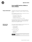
System overview
This demonstration board consists of an isolated interleaved boost DC-DC converter and a
mixed frequency full bridge inverter used to deliver sinusoidal current at 50 Hz or 60 Hz to
the grid. The board is provided with a digital control section, capable of controlling the gridconnected operation as well as an MPPT (maximum power point tracking) algorithm. The
firmware has been implemented on a 32-bit STM32F1xx microcontroller, high-performance
ARM® Cortex™-M3 32-bit RISC core operating at a 72 MHz frequency, high-speed
embedded memories (512 Kbytes for Flash memory and 64 Kbytes of SRAM), and an
extensive range of enhanced I/Os and peripherals connected to two APB buses. The device
offers three 12-bit ADCs, four general-purpose 16-bit timers plus two advanced PWM
timers, as well as standard and advanced communication interfaces: two I2Cs, three SPIs,
two I2Ss, one SDIO, five USARTs, a USB and a CAN.
Figure 1.
250 W microinverter - digital section based on STM32F1xx
microcontroller
STM32
ARM® Cortex™-M3
32-bit RISC core
4/39
Doc ID 023556 Rev 1
AM15187v1
UM1561
2
Firmware workspace with IAR embedded workbench IDE
Firmware workspace with IAR embedded workbench
IDE
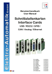
Opening IAR workbench editor, the workspace “250 W microinverter grid connected”
appears as shown in Figure 2:
Figure 2.
IAR embedded workbench IDE workspace
It is internally structured in several folders, in particular:
●
Doc: includes fw version file;
●
EWARMv5: includes cortexm3_macro.s (instruction wrappers for special Cortex-M3
instructions) and stm32f10x_vector.c (STM32F10x vector table for EWARM5);
●
FWLib: includes the firmware library with the .c file for each STM32F1xx internal
peripheral: for example, the stm32f10x_adc.c file provides all the ADC firmware
functions, stm32f10x_tim.c provides the TIM functions, and the same for other
peripherals;
●
User: includes all user-files developed;
●
Output: contains the “.map” and “.out” file.
Doc ID 023556 Rev 1
5/39
Firmware workspace with IAR embedded workbench IDE
UM1561
The user folder contains all .c files that contribute to the power and communication
management.
6/39
●
250WControl.c: the core of the firmware; it contains a lot of functions for the closed and
open loop control
●
DAC_Debug.c: configures the external DAC used for debug only
●
DataSensing.c: configures the data sensing section for closed loop control
●
DCAC_Inverter.c: contains all functions in regard to the DCAC section
●
DCDC_Inverter.c: contains all functions in regard to the DCDC section
●
DQ_PhaseLockedLoop.c: contains the DQ-PLL implementation for a single-phase and
the anti-islanding protection routine
●
hw_config.c: configures the RCC, NVIC, GPIOs, Systick, DAC and display peripherals
●
lcd.c: the library for the color display
●
main.c: includes the main loop function and the system parameters management with
joystick
●
PI_Regulator.c: includes several PI regulators for the closed loop control
●
PLL_Regulator.c: includes two PI regulators for the closed loop control, the
PID_Bus_Voltage and PLL_PID regulator
●
Solar MPPT: includes the maximum power point tracking algorithm for the DC-DC
control
●
Solar_Mul_Div.c: includes the calculations used for the closed loop control
●
stm32f10x_it.c: includes main interrupt service routines.
Doc ID 023556 Rev 1
UM1561 STM32F1xx microcontroller - several peripherals used to manage the STEVAL-ISV003V1
3
STM32F1xx microcontroller - several peripherals
used to manage the STEVAL-ISV003V1
demonstration board
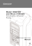
The STEVAL-ISV003V1 is a 250 W dual stage converter digitally controlled by a 32-bit
STM32F1xx microcontroller to allow operation in grid connection while performing an MPPT
algorithm on the PV panel side. Several hardware peripherals, embedded in the
microcontroller, have been used to control the system and to allow communication with an
external unit. In particular, the power board is made up of two sections, a DC-DC converter
and a DC-AC converter. Figure 3 shows an overview of the main blocks used to design the
system.
Figure 3.
Description of the main hardware parts in STEVAL-ISV003V1
DC/DC converter
DC/AC converter
AC filter
AUX PS
µC unit
and LCD
JTAG connector
Debug connector
RS-232 port
AM15189v1
Doc ID 023556 Rev 1
7/39
STM32F1xx - internal peripherals for DC-DC section
4
UM1561
STM32F1xx - internal peripherals for DC-DC section
The DC-DC converter is managed by two PWM timers, configured in master-slave in such a
way as to have two phase-shifted signals. In particular, the general timer TIM2 is configured
as master with “Center Aligned” mode counting. The overflow of the digital counter at the
up-counting synchronizes another general timer, TIM3, to work in slave mode. Hardware
synchronization allows no delay time between the timers and two signals are generated with
180 deg. phase shift.
DCDC_Converter.c:
#define TIM_PERIOD
LocalDevice.Init.Counter
#define TIM2_PERIOD
MODE
(TIM_PERIOD >> 1) // DIVIDED BY 2 CENTER ALIGNED
#define TIM2_INIT_PULSE
(TIM2_PERIOD >> 1)// DIVIDED BY 2 50% TIM2 PERIOD
#define TIM3_PERIOD
MODE
(TIM_PERIOD >> 1) // DIVIDED BY 2 CENTER ALIGNED
#define TIM3_INIT_PULSE
(TIM3_PERIOD >> 1) // DIVIDED BY 2 50% TIM2 PERIOD
Set the counting period of the PWM timers (TIM2_PERIOD and TIM3_PERIOD), and set
the duty cycle value at 50% (TIM2_INIT_PULSE, TIM3_INIT_PULSE). In
DCDC_Converter.h the DCDC_COUNTER is the TIM_PERIOD reference value.
The .c file defines all functions useful in managing the DC-DC section, in particular:
●
DCDC_Init(PDCDC_TypeDef_t pDCDCInit);
●
DCDC_SendCommand(DCDC_Commands_t cmd);
●
DCDC_GetStatus();
●
DCDC_GetConfiguration(PDCDC_TypeDef_t pDCDCInit);
●
DCDC_GetDutyCycle();
●
DCDC_GetFrequency();
●
DCDC_RefreshDisplay(DCDC_Error_t err, u32 steps, u32 changes).
DCDC_Init(….)
DCAC_Error_t DCAC_Init(PDCAC_TypeDef_t pDCACInit)
{
DCAC_Error_t nRet;
nRet = DCAC_ERROR_INVALID_PARAMETER;
if (pDCACInit)
{
nRet = DCAC_ERROR_ON_INIT;
if (LocalDevice.State != DCAC_Running)
{
LocalDevice.Init.Counter
= pDCACInit->Counter;
LocalDevice.Init.DeadTime = pDCACInit->DeadTime;
LocalDevice.State = DCAC_Stopped;
8/39
Doc ID 023556 Rev 1
UM1561
STM32F1xx - internal peripherals for DC-DC section
/*Init peripherals */
DCAC_GPIO_Configuration();
DCAC_TIMx_Configuration();
DCAC_SetDeadTime(LocalDevice.Init.DeadTime);
nRet = DCAC_ERROR_NONE;
}
}
return nRet;
}
where:
●
DCAC_GPIO_Configuration(); is (Configuration of the GPIO pin for PWM timers)
●
DCAC_TIMx_Configuration(); is (Configuration of PWM timers, TIM2 and TIM3,
for master-slave mode).
DCDC_SendCommand(….)
DCDC_Error_t DCDC_SendCommand(DCDC_Commands_t cmd)
{
DCDC_Error_t nRet;
nRet = DCDC_ERROR_INVALID_COMMAND;
if (cmd == DCDC_ConverterStart)
{
nRet = DCDC_ERROR_ON_SEND_COMMAND;
if (DCDC_GetStatus() != DCDC_Running)
{
LocalDevice.State = DCDC_Running;
// TIMx enable counter
TIM_Cmd(TIM2, ENABLE);
nRet = DCDC_ERROR_NONE;
}
}
else
if (cmd == DCDC_ConverterStop)
{
nRet = DCDC_ERROR_ON_SEND_COMMAND;
if (DCDC_GetStatus() != DCDC_Stopped)
{
LocalDevice.State = DCDC_Stopped;
Doc ID 023556 Rev 1
9/39
STM32F1xx - internal peripherals for DC-DC section
UM1561
// TIMx disable counter
TIM_Cmd(TIM2, DISABLE);
TIM_Cmd(TIM3, DISABLE);
DCDC_TIMx_Configuration();
nRet = DCDC_ERROR_NONE;
}
}
return nRet;
}
where:
10/39
●
TIM_Cmd(TIM2, ENABLE); is (Enables PWM timer, TIM2, and the synchronization
with TIM3)
●
TIM_Cmd(TIM2, DISABLE); is (Stops the PWM timers, TIM2 and TIM3).
Doc ID 023556 Rev 1
UM1561
STM32F1xx - internal peripherals for DC-AC section
5
STM32F1xx - internal peripherals for DC-AC section
The DC-AC converter is managed by one PWM timer and a GPIO pin, synchronized in order
to control two legs of the inverter at different switching frequencies. The advanced PWM
timer, TIM8, is used to control the high frequency leg, and the GPIO pin for the low
frequency leg. Only one output of the TIM8 is used and the same is true for the GPIO
peripheral. The advanced timer is configured in center alignment mode in order to trigger
the ADC at the up-counting of the counter. Figure 4 shows the PWM mode and the trigger
events for ADC.
Figure 4.
Center alignment mode for TIM8 timer and trigger event for ADC
07-?42'/3ELECTION07-?42'/-ODE?5PDATE
8RQRYHUIORZ5(35$7( 07-#ENTERALIGNEDMODE
&RQWURO
/RRS$'
,65
8RQRYHUIORZ5(35$7( 7LPHU5HV QV
:DLW6WDWH
PDLQORRS
6DPSOLQJ3HULRG7V XV N+]
!-V
DataSensing.c
void DS_TIMx_Configuration(void)
{
//
TIM8 Configuration: PWM1 Mode
TIM_TimeBaseStructure.TIM_Period = ((DataSensing.Init.Counter) >> 1);
TIM_TimeBaseStructure.TIM_Prescaler = 0;
TIM_TimeBaseStructure.TIM_ClockDivision = 0;
TIM_TimeBaseStructure.TIM_CounterMode = TIM_CounterMode_CenterAligned1;
TIM_TimeBaseStructure.TIM_RepetitionCounter = 1;
TIM_TimeBaseInit(TIM8, &TIM_TimeBaseStructure);
TIM_SelectOutputTrigger(TIM8, TIM_TRGOSource_Update);
}
where
●
TIM_SelectOutputTrigger(TIM8, TIM_TRGOSource_Update); is (Set the
TIM8 output for ADC triggering).
The DS_TIMx_Configuration includes the configuration code for the advanced timer TIM8.
The counter value (DataSensing.Init.Counter) is defined inside the DCDC_Converter.h file.
Doc ID 023556 Rev 1
11/39
STM32F1xx - internal peripherals for DC-AC section
UM1561
The repetition counter is set to 1 in order to have an update_event at the center of the
counting, as shown in Figure 4.
Figure 5.
Repetition counter settings for advanced timer
#ENTERALIGNEDMODE
%DGEALIGNEDMODE
5PCOUNTING
$OWNCOUNTING
#OUNTER
4)-X?#.4
4)-X?2#2 5%6
4)-X?2#2 5%6
4)-X?2#2 5%6
4)-X?2#2 5%6
4)-X?2#2
AND
RESYNCHRONIZATION
5%6
BY37
5%6
BY37
BY37
5PDATE%VENT 0RELOADREGISTERSTRANSFERREDTOACTIVEREGISTERSANDUPDATEINTERRUPTGENERATED
!-V
DCAC_Inverter.c:
The .c file defines all functions useful in managing the DC-AC section, in particular:
●
DCAC_Init(PDCAC_TypeDef_t pDCACInit);
●
DCAC_SendCommand(DCAC_Commands_t cmd);
●
DCAC_SetPulse(u32 PulseCurrent, u32 PulseVoltage);
●
DCAC_GetStatus();
●
DCAC_GetConfiguration(PDCAC_TypeDef_t pDCACInit);
●
DCAC_RefreshDisplay(DCAC_Error_t err, u32 steps, u32 PulseCurrent, u32 changes).
DCAC_Init(….):
DCAC_Error_t DCAC_Init(PDCAC_TypeDef_t pDCACInit)
{
DCAC_Error_t nRet;
nRet = DCAC_ERROR_INVALID_PARAMETER;
if (pDCACInit)
{
nRet = DCAC_ERROR_ON_INIT;
if (LocalDevice.State != DCAC_Running)
{
LocalDevice.Init.Counter
= pDCACInit->Counter;
LocalDevice.Init.DeadTime = pDCACInit->DeadTime;
LocalDevice.State = DCAC_Stopped;
12/39
Doc ID 023556 Rev 1
UM1561
STM32F1xx - internal peripherals for DC-AC section
/*Init peripherals */
DCAC_GPIO_Configuration();
DCAC_TIMx_Configuration();
DCAC_SetDeadTime(LocalDevice.Init.DeadTime);
nRet = DCAC_ERROR_NONE;
}
}
return nRet;
}
where:
●
DCAC_GPIO_Configuration(); is (Configuration of the GPIO pin for TIM8 timer and for
GPIO function)
●
DCAC_TIMx_Configuration(); is (Configuration of PWM timer).
This function includes the init code for the advanced timer TIM8 and GPIO.
DCAC_SendCommand(…):
This function includes the start/stop command for the output of the advanced timer TIM8
(inverter modulation).
DCAC_Error_t DCAC_SendCommand(DCAC_Commands_t cmd)
{
DCAC_Error_t nRet;
nRet = DCAC_ERROR_INVALID_COMMAND;
if (cmd == DCAC_Start)
{
nRet = DCAC_ERROR_ON_SEND_COMMAND;
if (DCAC_GetStatus() != DCAC_Running)
{
LocalDevice.State = DCAC_Running;
// TIMx enable counter
TIM_CtrlPWMOutputs(TIM8, ENABLE);
nRet = DCAC_ERROR_NONE;
}
}
else
if (cmd == DCAC_Stop)
{
nRet = DCAC_ERROR_ON_SEND_COMMAND;
Doc ID 023556 Rev 1
13/39
STM32F1xx - internal peripherals for DC-AC section
UM1561
if (DCAC_GetStatus() != DCAC_Stopped)
{
LocalDevice.State = DCAC_Stopped;
TIM_CtrlPWMOutputs(TIM8, DISABLE);
// TIMx disable counter
nRet = DCAC_ERROR_NONE;
}
}
return nRet;
}
where:
●
TIM_CtrlPWMOutputs(TIM8, ENABLE); is (Enables TIM8 timer for DCAC section
and starts DataSensing acquisitions)
●
TIM_CtrlPWMOutputs(TIM8, DISABLE); is (Stops TIM8 timer and stops
DataSensing acquisitions).
DCAC_SetPulse(…):
This function sets the PWM pulse value produced by the calculations of the closed loop
control. It is called by the microcontroller each control cycle after board startup.
DCAC_Error_t DCAC_SetPulse(u32 PulseChannel1, u32 PulseChannel2)
{
DCAC_Error_t nRet;
TIM_SetCompare2(TIM8, PulseChannel1);
nRet = DCAC_ERROR_NONE;
return nRet;
}
where:
●
14/39
TIM_SetCompare2(TIM8, PulseChannel1); is (Set the pulse value of the TIM8
in the capture compare register).
Doc ID 023556 Rev 1
UM1561
6
Data sensing section for the closed loop control
Data sensing section for the closed loop control
The firmware implemented for the closed loop control needs a good sensing procedure in
order to regulate the bus voltage to inject sinusoidal current to the grid and also for the input
control of the DC-DC converter that performs an MPPT control. The accuracy of the control
block is also very important in order to achieve system efficiency.
DataSensing.c:
The .c file defines all functions useful in managing the data sensing section, in particular:
●
DS_Init(PDS_TypeDef_t pDSInit);
●
DS_SendCommand(DS_Commands_t cmd);
●
DS_GetStatus();
●
DS_GetData();
●
DS_GetConfiguration(PDS_TypeDef_t pDSInit);
●
DS_RefreshDisplay(DS_Error_t err);
●
DS_SetAcquistionEvent(PFN_ON_ACQUISTION pfFn).
DS_Init(..):
This function includes the init code for the ADC1 e ADC2 configuration:
DS_Error_t DS_Init(PDS_TypeDef_t pDSInit)
{
DS_Error_t nRet;
nRet = DS_ERROR_INVALID_PARAMETER;
if (pDSInit)
{
nRet = DS_ERROR_ON_INIT;
if (DataSensing.State != DS_Running)
{
DataSensing.Init.Counter
= pDSInit->Counter;
DataSensing.Init.DataRegister
= pDSInit->DataRegister;
DataSensing.Init.RegisterSize
= pDSInit->RegisterSize;
DataSensing.Init.OnAcquisition = pDSInit->OnAcquisition;
DataSensing.State = DS_Stopped;
/*Init peripherals */
DS_GPIO_Configuration();
DS_TIMx_Configuration();
DS_DMA_Configuration();
DS_ADCx_Configuration();
nRet = DS_ERROR_NONE;
}
Doc ID 023556 Rev 1
15/39
Data sensing section for the closed loop control
UM1561
}
return nRet;
}
where:
●
DS_GPIO_Configuration(); is (Configures the GPIO pins)
●
DS_TIMx_Configuration(); is (Configures the TIM8 timer)
●
DS_DMA_Configuration(); is (Configures the DMA)
●
DS_DMA_Configuration(); is (Configures the ADC).
DS_GPIO_Configuration(..):
The following GPIO pins are configured as “Analog Input” in order to connect the external
sensing section with the internal ADC.
/*************************************************************************
* Function Name
: GPIO_Configuration
* Description
: Configures the different GPIO ports for data sensing.
* Input
: None
* Output
: None
* Return
: None
*************************************************************************/
void DS_GPIO_Configuration(void)
{
/* Configure PC.0 PC.1 (ADC Channel10, 11) as analog input -----------*/
GPIO_InitStructure.GPIO_Pin =
GPIO_Pin_0|GPIO_Pin_1|GPIO_Pin_2|GPIO_Pin_3|GPIO_Pin_4|GPIO_Pin_5;
GPIO_InitStructure.GPIO_Mode = GPIO_Mode_AIN;
GPIO_Init(GPIOC, &GPIO_InitStructure);
/*For Debug pourpouse*/
/* Configure Test Pin:PC9-----------------------------------*/
GPIO_InitStructure.GPIO_Pin
= GPIO_Pin_9;
GPIO_InitStructure.GPIO_Mode
= GPIO_Mode_Out_PP;
GPIO_InitStructure.GPIO_Speed = GPIO_Speed_50MHz;
GPIO_Init(GPIOC, &GPIO_InitStructure);
}
DS_TIMx_Configuration(..):
The DS_TIMx_Configuration includes the configuration code for the advanced timer TIM8
useful also for ADC triggering.
void DS_TIMx_Configuration(void)
{
//
TIM8 Configuration: PWM1 Mode
TIM_TimeBaseStructure.TIM_Period = ((DataSensing.Init.Counter) >> 1);
TIM_TimeBaseStructure.TIM_Prescaler = 0;
16/39
Doc ID 023556 Rev 1
UM1561
Data sensing section for the closed loop control
TIM_TimeBaseStructure.TIM_ClockDivision = 0;
TIM_TimeBaseStructure.TIM_CounterMode = TIM_CounterMode_CenterAligned1;
TIM_TimeBaseStructure.TIM_RepetitionCounter = 1;
TIM_TimeBaseInit(TIM8, &TIM_TimeBaseStructure);
TIM_SelectOutputTrigger(TIM8, TIM_TRGOSource_Update);
}
where:
●
TIM_SelectOutputTrigger(TIM8, TIM_TRGOSource_Update); is (Configures
the TIM8 as trigger for ADC1 and ADC2).
DS_DMA_Configuration(..):
The direct memory access (DMA1) peripheral is configured to store the information
acquired by the ADC in a buffer called the data register. It is a vector that includes all the I/O
information, for example AC line voltage, AC line current, DC bus voltage, DC panel current,
and DC panel voltage.
/*************************************************************************
* Function Name
: DS_DMA_Configuration
* Description
: Analog to digital converter configuration
* Input
: NONE
* Return
: None
*************************************************************************/
void DS_DMA_Configuration(void)
{
/* DMA1 channel1 configuration ----------------------------------------*/
DMA_DeInit(DMA1_Channel1);
DMA_InitStructure.DMA_PeripheralBaseAddr = ADC1_DR_Address;
DMA_InitStructure.DMA_MemoryBaseAddr =
(vu32)DataSensing.Init.DataRegister;
DMA_InitStructure.DMA_DIR = DMA_DIR_PeripheralSRC;
DMA_InitStructure.DMA_BufferSize = DataSensing.Init.RegisterSize;
DMA_InitStructure.DMA_PeripheralInc = DMA_PeripheralInc_Disable;
DMA_InitStructure.DMA_MemoryInc = DMA_MemoryInc_Enable;
DMA_InitStructure.DMA_PeripheralDataSize = DMA_PeripheralDataSize_Word;
DMA_InitStructure.DMA_MemoryDataSize = DMA_MemoryDataSize_Word;
DMA_InitStructure.DMA_Mode = DMA_Mode_Circular;
DMA_InitStructure.DMA_Priority = DMA_Priority_High;
DMA_InitStructure.DMA_M2M = DMA_M2M_Disable;
DMA_Init(DMA1_Channel1, &DMA_InitStructure);
/* Enable DMA1 channel1 */
DMA_Cmd(DMA1_Channel1, ENABLE);
/* Clear channel1 transfer complete flag */
Doc ID 023556 Rev 1
17/39
Data sensing section for the closed loop control
UM1561
DMA_ClearFlag(DMA1_FLAG_TC1);
}
where
●
(vu32)DataSensing.Init.DataRegister; is (Data Register stores the I/O
information).
DS_ADCx_Configuration(….):
The ADC is triggered by an external trigger. The update event of TIM8 generates the trigger
signal to acquire the I/O information.
void DS_ADCx_Configuration(void)
{
/* ADC1 configuration -------------------------------------------------*/
ADC_InitStructure.ADC_Mode = ADC_Mode_RegSimult;
ADC_InitStructure.ADC_ScanConvMode = ENABLE;
ADC_InitStructure.ADC_ContinuousConvMode = DISABLE;
ADC_InitStructure.ADC_ExternalTrigConv =
ADC_ExternalTrigConv_Ext_IT11_TIM8_TRGO;
ADC_InitStructure.ADC_DataAlign = ADC_DataAlign_Left;
ADC_InitStructure.ADC_NbrOfChannel = 3;
ADC_Init(ADC1, &ADC_InitStructure);
/* ADC1 regular channel10 configuration */
ADC_RegularChannelConfig(ADC1, ADC_Channel_10, 1,
ADC_SampleTime_1Cycles5); //AC Line current
/* ADC1 regular channel12 configuration */
ADC_RegularChannelConfig(ADC1, ADC_Channel_12, 2,
ADC_SampleTime_1Cycles5); //DC Panel current
/* ADC1 regular channel12 configuration */
ADC_RegularChannelConfig(ADC1, ADC_Channel_14, 3,
ADC_SampleTime_1Cycles5); //BUS Voltage
/*External trigger enabled*/
ADC_ExternalTrigConvCmd(ADC1, ENABLE);
//AFIO_REMAP for Trigger on Tim8 TRGO
GPIO_PinRemapConfig(GPIO_Remap_ADC1_ETRGREG, ENABLE);
/* Enable ADC1 DMA */
ADC_DMACmd(ADC1, ENABLE);
/* ADC2 configuration ------------------------------------------------*/
ADC_InitStructure.ADC_Mode = ADC_Mode_RegSimult;
ADC_InitStructure.ADC_ScanConvMode = ENABLE;
ADC_InitStructure.ADC_ContinuousConvMode = DISABLE;
ADC_InitStructure.ADC_ExternalTrigConv = ADC_ExternalTrigConv_None;
ADC_InitStructure.ADC_DataAlign = ADC_DataAlign_Left;
18/39
Doc ID 023556 Rev 1
UM1561
Data sensing section for the closed loop control
ADC_InitStructure.ADC_NbrOfChannel = 3;
ADC_Init(ADC2, &ADC_InitStructure);
/* ADC2 regular channel11 configuration */
ADC_RegularChannelConfig(ADC2, ADC_Channel_11, 1,
ADC_SampleTime_1Cycles5);
/* ADC2 regular channel13 configuration */
ADC_RegularChannelConfig(ADC2, ADC_Channel_13, 2,
ADC_SampleTime_1Cycles5); //PC3 PANEL VOLTAGE
/* ADC2 regular channel15 configuration not used */
ADC_RegularChannelConfig(ADC2, ADC_Channel_15, 3,
ADC_SampleTime_1Cycles5);
/*External trigger enabled*/
ADC_ExternalTrigConvCmd(ADC2, ENABLE);
ADC_ITConfig(ADC1, ADC_IT_EOC , ENABLE);
DS_ADC_EnableAndCalibrate(ADC1);
DS_ADC_EnableAndCalibrate(ADC2);
}
The ADC1 converts the following information at different channels:
●
ADC_Channel_10 -> AC line current
●
ADC_Channel_12 -> DC panel current
●
ADC_Channel_14 -> DC bus voltage.
/* ADC2 configuration -------------------------------------------------*/
ADC_InitStructure.ADC_Mode = ADC_Mode_RegSimult;
ADC_InitStructure.ADC_ScanConvMode = ENABLE;
ADC_InitStructure.ADC_ContinuousConvMode = DISABLE;
ADC_InitStructure.ADC_ExternalTrigConv = ADC_ExternalTrigConv_None;
ADC_InitStructure.ADC_DataAlign = ADC_DataAlign_Left;
ADC_InitStructure.ADC_NbrOfChannel = 3;
ADC_Init(ADC2, &ADC_InitStructure);
/* ADC2 regular channel11 configuration */
ADC_RegularChannelConfig(ADC2, ADC_Channel_11, 1,
ADC_SampleTime_1Cycles5);
/* ADC2 regular channel13 configuration */
ADC_RegularChannelConfig(ADC2, ADC_Channel_13, 2,
ADC_SampleTime_1Cycles5);
/* ADC2 regular channel15 configuration not used */
ADC_RegularChannelConfig(ADC2, ADC_Channel_15, 3,
ADC_SampleTime_1Cycles5);
/*External trigger enabled*/
ADC_ExternalTrigConvCmd(ADC2, ENABLE);
Doc ID 023556 Rev 1
19/39
Data sensing section for the closed loop control
ADC_ITConfig(ADC1, ADC_IT_EOC , ENABLE);
DS_ADC_EnableAndCalibrate(ADC1);
DS_ADC_EnableAndCalibrate(ADC2);
The ADC2 converts the following information at different channels:
20/39
●
ADC_Channel_11 -> AC line voltage
●
ADC_Channel_13 -> DC panel voltage.
Doc ID 023556 Rev 1
UM1561
UM1561
7
STM32F1xx MCU peripherals configuration
STM32F1xx MCU peripherals configuration
hw_config.c:
The .c file defines all functions useful to init the internal and external peripherals, in
particular:
●
RCC_Config(): configures main system clocks & power;
●
NVIC_Configuration(): configures NVIC and vector table base location;
●
GPIO_Configuration(): configures the different GPIO ports;
●
SysTick_Config(): configure a SysTick Base time to 1 ms;
●
InitControl(..): initializes the parameters for the control algorithm (open/closed loop);
●
DAC_Init(): configures DAC peripheral used only for debug;
●
STM3210E_LCD_Init(): initializes the LCD.
void SetSystem(void)
{
/* RCC configuration */
RCC_Config();
/*Interrupt vector*/
NVIC_Configuration();
/*GPIO Conf....*/
GPIO_Configuration();
/* SysTick for delay function*/
SysTick_Config();
/*Init 250W Control algorithm*/
InitControl(ClosedLoop);
//Init DAC Control
DAC_Init(DAC_COUNTER, DAC_ADDRESS);
/*LCD int */
STM3210E_LCD_Init();
/* Clear the LCD */
LCD_Clear(White);
/*Photovoltaic data transfer Init*/
PHOTOVSDK_Init();
}
Doc ID 023556 Rev 1
21/39
STM32F1xx MCU peripherals configuration
UM1561
where:
22/39
●
RCC_Config(); is (Configures main system clocks and power)
●
NVIC_Configuration(); is (Configures NVIC and Vector Table base location)
●
GPIO_Configuration(); is (Configures the different GPIO ports)
●
SysTick_Config(); is (Configures the different GPIO ports)
●
InitControl(ClosedLoop); is (Initializes the parameters for the control algorithm
(open/closed loop))
●
DAC_Init(DAC_COUNTER, DAC_ADDRESS); is (Initializes the parameters for the
control algorithm (open/closed loop))
●
STM3210E_LCD_Init(); is (Initializes the LCD)
●
LCD_Clear(White); is (Initializes the LCD).
Doc ID 023556 Rev 1
UM1561
8
Implementation of digital phase locked loop
Implementation of digital phase locked loop
DQ_PhaseLockedLoop.c:
The .c file defines the DQ PLL implementation for a single-phase inverter. It is used for the
closed loop control in order to estimate the grid angle and to detect the grid voltage before
injecting current.
#include "stm32f10x_lib.h"
#include "Solar_Mul_Div.h"
#include "250WControl.h"
#define STEPS
512
/*number of entries of the sine look up table*/
#define OFFSET
64
/* Offset for cos(Theta)=sin_cos_Table[index_sin+offset]*/
#define INDUCTANCE_VALUE
65
//1117----- 34mH in q1.15= 34*10-3*2-15/
#define SAMPLES
256
#define SAMPLING_TIME
(s16)((4096)-1)
SystStatus_t Freq_Control= FREQ_OUT_OF_RANGE;
SystStatus_t GDVoltage = GRID_VOLTAGE_OUT_OF_RANGE;
where:
●
512: is (Number of entries of the sine look-up table).
The following code shows the look-up table with 512 elements in hexadecimal format.
//*********************** 512 elements *********************************
const s16 Sin_Cos_Table[STEPS] = {
//tabella USATA x IL VECTOR
0x0000, 0xFE6E, 0xFCDC, 0xFB4A, 0xF9B9, 0xF827, 0xF696, 0xF505, 0xF375,
0xF1E5, 0xF055, 0xEEC7, 0xED38, 0xEBAB, 0xEA1E, 0xE893,
0xE708, 0xE57E, 0xE3F5, 0xE26D, 0xE0E7, 0xDF61, 0xDDDD, 0xDC5A, 0xDAD8,
0xD958, 0xD7DA, 0xD65D, 0xD4E1, 0xD368, 0xD1EF, 0xD079,
0xCF05, 0xCD92, 0xCC22, 0xCAB3, 0xC946, 0xC7DC, 0xC674, 0xC50E, 0xC3AA,
0xC248, 0xC0E9, 0xBF8D, 0xBE32, 0xBCDB, 0xBB86, 0xBA33,
0xB8E4, 0xB797, 0xB64C, 0xB505, 0xB3C1, 0xB27F, 0xB141, 0xB005, 0xAECD,
0xAD97, 0xAC65, 0xAB36, 0xAA0B, 0xA8E3, 0xA7BE, 0xA69C,
0xA57E, 0xA463, 0xA34C, 0xA239, 0xA129, 0xA01D, 0x9F14, 0x9E0F, 0x9D0E,
0x9C11, 0x9B18, 0x9A23, 0x9931, 0x9843, 0x975A, 0x9674,
0x9593, 0x94B6, 0x93DC, 0x9307, 0x9236, 0x916A, 0x90A1, 0x8FDD, 0x8F1E,
0x8E62, 0x8DAB, 0x8CF9, 0x8C4B, 0x8BA1, 0x8AFC, 0x8A5B,
0x89BF, 0x8927, 0x8894, 0x8806, 0x877C, 0x86F7, 0x8676, 0x85FB, 0x8583,
0x8511, 0x84A3, 0x843B, 0x83D7, 0x8377, 0x831D, 0x82C7,
0x8276, 0x822A, 0x81E3, 0x81A1, 0x8163, 0x812B, 0x80F7, 0x80C8, 0x809E,
0x8079, 0x8059, 0x803E, 0x8028, 0x8017, 0x800A, 0x8003,
0x8000, 0x8003, 0x800A, 0x8017, 0x8028, 0x803E, 0x8059, 0x8079, 0x809E,
0x80C8, 0x80F7, 0x812B, 0x8163, 0x81A1, 0x81E3, 0x822A,
0x8276, 0x82C7, 0x831D, 0x8377, 0x83D7, 0x843B, 0x84A3, 0x8511, 0x8583,
0x85FB, 0x8676, 0x86F7, 0x877C, 0x8806, 0x8894, 0x8927,
0x89BF, 0x8A5B, 0x8AFC, 0x8BA1, 0x8C4B, 0x8CF9, 0x8DAB, 0x8E62, 0x8F1E,
0x8FDD, 0x90A1, 0x916A, 0x9236, 0x9307, 0x93DC, 0x94B6,
Doc ID 023556 Rev 1
23/39
Implementation of digital phase locked loop
UM1561
0x9593, 0x9674, 0x975A, 0x9843, 0x9931, 0x9A23, 0x9B18, 0x9C11, 0x9D0E,
0x9E0F, 0x9F14, 0xA01D, 0xA129, 0xA239, 0xA34C, 0xA463,
0xA57E, 0xA69C, 0xA7BE, 0xA8E3, 0xAA0B, 0xAB36, 0xAC65, 0xAD97, 0xAECD,
0xB005, 0xB141, 0xB27F, 0xB3C1, 0xB505, 0xB64C, 0xB797,
0xB8E4, 0xBA33, 0xBB86, 0xBCDB, 0xBE32, 0xBF8D, 0xC0E9, 0xC248, 0xC3AA,
0xC50E, 0xC674, 0xC7DC, 0xC946, 0xCAB3, 0xCC22, 0xCD92,
0xCF05, 0xD079, 0xD1EF, 0xD368, 0xD4E1, 0xD65D, 0xD7DA, 0xD958, 0xDAD8,
0xDC5A, 0xDDDD, 0xDF61, 0xE0E7, 0xE26D, 0xE3F5, 0xE57E,
0xE708, 0xE893, 0xEA1E, 0xEBAB, 0xED38, 0xEEC7, 0xF055, 0xF1E5, 0xF375,
0xF505, 0xF696, 0xF827, 0xF9B9, 0xFB4A, 0xFCDC, 0xFE6E,
0x0000, 0x0192, 0x0324, 0x04B6, 0x0647, 0x07D9, 0x096A, 0x0AFB, 0x0C8B,
0x0E1B, 0x0FAB, 0x1139, 0x12C8, 0x1455, 0x15E2, 0x176D,
0x18F8, 0x1A82, 0x1C0B, 0x1D93, 0x1F19, 0x209F, 0x2223, 0x23A6, 0x2528,
0x26A8, 0x2826, 0x29A3, 0x2B1F, 0x2C98, 0x2E11, 0x2F87,
0x30FB, 0x326E, 0x33DE, 0x354D, 0x36BA, 0x3824, 0x398C, 0x3AF2, 0x3C56,
0x3DB8, 0x3F17, 0x4073, 0x41CE, 0x4325, 0x447A, 0x45CD,
0x471C, 0x4869, 0x49B4, 0x4AFB, 0x4C3F, 0x4D81, 0x4EBF, 0x4FFB, 0x5133,
0x5269, 0x539B, 0x54CA, 0x55F5, 0x571D, 0x5842, 0x5964,
0x5A82, 0x5B9D, 0x5CB4, 0x5DC7, 0x5ED7, 0x5FE3, 0x60EC, 0x61F1, 0x62F2,
0x63EF, 0x64E8, 0x65DD, 0x66CF, 0x67BD, 0x68A6, 0x698C,
0x6A6D, 0x6B4A, 0x6C24, 0x6CF9, 0x6DCA, 0x6E96, 0x6F5F, 0x7023, 0x70E2,
0x719E, 0x7255, 0x7307, 0x73B5, 0x745F, 0x7504, 0x75A5,
0x7641, 0x76D9, 0x776C, 0x77FA, 0x7884, 0x7909, 0x798A, 0x7A05, 0x7A7D,
0x7AEF, 0x7B5D, 0x7BC5, 0x7C29, 0x7C89, 0x7CE3, 0x7D39,
0x7D8A, 0x7DD6, 0x7E1D, 0x7E5F, 0x7E9D, 0x7ED5, 0x7F09, 0x7F38, 0x7F62,
0x7F87, 0x7FA7, 0x7FC2, 0x7FD8, 0x7FE9, 0x7FF6, 0x7FFD,
0x7FFF, 0x7FFD, 0x7FF6, 0x7FE9, 0x7FD8, 0x7FC2, 0x7FA7, 0x7F87, 0x7F62,
0x7F38, 0x7F09, 0x7ED5, 0x7E9D, 0x7E5F, 0x7E1D, 0x7DD6,
0x7D8A, 0x7D39, 0x7CE3, 0x7C89, 0x7C29, 0x7BC5, 0x7B5D, 0x7AEF, 0x7A7D,
0x7A05, 0x798A, 0x7909, 0x7884, 0x77FA, 0x776C, 0x76D9,
0x7641, 0x75A5, 0x7504, 0x745F, 0x73B5, 0x7307, 0x7255, 0x719E, 0x70E2,
0x7023, 0x6F5F, 0x6E96, 0x6DCA, 0x6CF9, 0x6C24, 0x6B4A,
0x6A6D, 0x698C, 0x68A6, 0x67BD, 0x66CF, 0x65DD, 0x64E8, 0x63EF, 0x62F2,
0x61F1, 0x60EC, 0x5FE3, 0x5ED7, 0x5DC7, 0x5CB4, 0x5B9D,
0x5A82, 0x5964, 0x5842, 0x571D, 0x55F5, 0x54CA, 0x539B, 0x5269, 0x5133,
0x4FFB, 0x4EBF, 0x4D81, 0x4C3F, 0x4AFB, 0x49B4, 0x4869,
0x471C, 0x45CD, 0x447A, 0x4325, 0x41CE, 0x4073, 0x3F17, 0x3DB8, 0x3C56,
0x3AF2, 0x398C, 0x3824, 0x36BA, 0x354D, 0x33DE, 0x326E,
0x30FB, 0x2F87, 0x2E11, 0x2C98, 0x2B1F, 0x29A3, 0x2826, 0x26A8, 0x2528,
0x23A6, 0x2223, 0x209F, 0x1F19, 0x1D93, 0x1C0B, 0x1A82,
0x18F8, 0x176D, 0x15E2, 0x1455, 0x12C8, 0x1139, 0x0FAB, 0x0E1B, 0x0C8B,
0x0AFB, 0x096A, 0x07D9, 0x0647, 0x04B6, 0x0324, 0x0192,
};
Calc_Theta_Grid (….):
The main function “Calc_Theta_Grid()” includes the code for the grid angle estimation and
anti-islanding protection:
void Calc_Theta_Grid(s16 Input_Integration)
{
static s32 Delta_Theta_tmp=0;
24/39
Doc ID 023556 Rev 1
UM1561
Implementation of digital phase locked loop
static s16 Delta_Theta=0;
static u16 freq_monitor_time=0;
mul_q15_q15_q31(Input_Integration,SAMPLING_TIME,&Delta_Theta_tmp);
Delta_Theta = (s16)(Delta_Theta_tmp>>16);
Theta=Theta+Delta_Theta;//
Theta_time++;
if(zero_detect==50)
{
VqFiltered_min=65500;
VqFiltered_max=0;
Theta_time=0;
zero_detect=0;
}
VqFiltered_prec = (u16)(Grid_Volt_q_d.qV_Quadrature + 0x8000);
VqFiltered = (u16)(((s32)(((s32)VqFiltered<<8) - (s32)VqFiltered) +
(s32)(VqFiltered_prec))>>8);
if(VqFiltered>VqFiltered_max) VqFiltered_max=VqFiltered;
else if(VqFiltered<VqFiltered_min) VqFiltered_min=VqFiltered;
VqFiltered_mean=(u16)((VqFiltered_max+VqFiltered_min)>>1);
where:
●
Theta=Theta+Delta_Theta;// is (Grid angle estimation: Theta changes value
linearly each switching period between -32768 to 32768).
The anti-islanding protection is based on grid voltage and frequency monitoring. The “Vq”
DC-component, used for the first, is made up of an offset value (32768) plus a DC-value
function of the AC Vrms value (for example Vac=265 Vrms -> Vq=39080 or Vac=186 V ->
Vq=37150).
//265V max & 186V min
if((VqFiltered_mean>=39080 || VqFiltered_mean<=37150) &&
State_Control==GRID_INSERTION && MPPT_EN==TRUE && zero_detect>5 &&
Vacprot==TRUE)
{
GPIO_ResetBits(GPIOA, GPIO_Pin_1);
State_Control = STOP_WITH_DELAY;
Diagnostic_Control=GRID_VOLTAGE_OUT_OF_RANGE;
}
Doc ID 023556 Rev 1
25/39
Implementation of digital phase locked loop
UM1561
where:
●
37150 is (AC voltage protection based on Vq value).
The figure code shows the procedure to control the AC line before the microinverter startup: in this example, the AC line voltage must be comprised between 185 V and 265 V and
the frequency between 47 Hz and 53 Hz. If these conditions are satisfied for a fixed time
(10 sec), the state machine goes to the next step (DC-DC/DC-AC turned on).
//****************** ANTI-ISLANDING DETECTION *****************************
if(((Theta+0x8000)-Theta_previous)<=-20000)
{
zero_detect++;
//************* DIAGNOSTIC AC - VOLTAGE AND FREQ AT STARTUP ***************
//Freq 47 Hz - 53 Hz
//Vac 185V - 265V
if((State_Control==DIAGNOSTIC_AC_LINE) ||
(State_Control==DIAGNOSTIC_DC_LINE))
{
if((Theta_time>331 && Theta_time<375) && (VqFiltered_mean >= 37150 &&
VqFiltered_mean<=39080))
{
if(freq_monitor_time>=500) //10 sec
{
GDVoltage = GRID_VOLTAGE_INSIDE_RANGE;
Freq_Control = FREQ_INSIDE_RANGE;
freq_monitor_time=0;
}
if(Freq_Control==FREQ_OUT_OF_RANGE && GDVoltage ==
GRID_VOLTAGE_OUT_OF_RANGE)
freq_monitor_time++;
}
else
{
freq_monitor_time=0;
Grid_Voltage_max=0;
Grid_Voltage_min=0;
}
}
where:
26/39
●
37150 is (AC voltage RMS monitoring)
●
375 is (AC frequency monitoring)
●
500 is (listening time).
Doc ID 023556 Rev 1
UM1561
9
Digital closed loop control and diagnostic functions implemented
Digital closed loop control and diagnostic functions
implemented
250WControl.c:
This is the main file of the microinverter. It includes the firmware-code for the closed and
open loop control, the input and output protection and the LCD display management. The
first function, called InitControl(), contains the init data for the DC-DC and DC-AC section. In
particular, the DC-DC information is contained in the InitStructure, the DC-AC are contained
in the DCAC_InitStructure and the data sensing part in the DS_ InitStructure.
void InitControl(ControlMode_t mode)
{
GPIO_InitTypeDef GPIO_InitStructure;
DCDC_TypeDef_t InitStructure;
DCAC_TypeDef_t DCAC_InitStructure;
DS_TypeDef_t DS_InitStructure;
/*DCDC Converter configuration */
InitStructure.Counter = DCDC_COUNTER;
InitStructure.DutyCycle = DCDC_DUTYCYCLE;
InitStructure.frequency = DCDC_FREQUENCY;
DCDC_Init(&InitStructure);
/*DCAC Inverter init configuration*/
DCAC_InitStructure.Counter = DCAC_COUNTER;
DCAC_InitStructure.DeadTime = DCAC_DEADTIME;
DCAC_Init(&DCAC_InitStructure);
ControlMode = mode;
/*DataSensing Init configuration*/
DS_InitStructure.Counter = DCAC_COUNTER; //--the same counter of the
DCAC
DS_InitStructure.DataRegister =
(vu32 *)&DataSensingIO;
DS_InitStructure.RegisterSize = DATA_SENSING_SIZE;
if (mode == ClosedLoop)
DS_InitStructure.OnAcquisition = ExecControl;
else
DS_InitStructure.OnAcquisition = ExecControlOpenLoop;
DS_Init(&DS_InitStructure);
/*Calibration of data sensing ***AFTER DS_Init*** */
CalibrationControl();
/* Configure RELE
: PA1-----------------------------------*/
Doc ID 023556 Rev 1
27/39
Digital closed loop control and diagnostic functions implemented
GPIO_InitStructure.GPIO_Pin
= GPIO_Pin_1;
GPIO_InitStructure.GPIO_Mode
= GPIO_Mode_Out_PP;
UM1561
GPIO_InitStructure.GPIO_Speed = GPIO_Speed_50MHz;
GPIO_Init(GPIOA, &GPIO_InitStructure);
PID_Init_Integral_Part();
PID_Init(&Direct_Current_PID, &Quadrature_Current_PID,
&Reactive_Power_PID,&Active_Power_PID,&BUS_Voltage_PID,&DQ_PLL_PID,
&MPPT_PID);
//Get Control Parameters address
GetControlParametersAddress((PControlParam_t)&CtrlParam);
//Get Data Parameters address
GetDataParametersAddress((PPhotov_t)&Data);
}
where:
●
InitStructure.DutyCycle = DCDC_DUTYCYCLE; is (DC-DC data structure)
●
DCAC_InitStructure.Counter = DCAC_COUNTER; is (DC-AC data structure)
●
DS_InitStructure.Counter = DCAC_COUNTER; is (Sensing data structure).
The StartControl() function defines the init configuration for all PID regulators. It contains
also the start commands for the power section.
void StartControl()
{
PID_Init_Integral_Part();
PID_Init(&Direct_Current_PID, &Quadrature_Current_PID,
&Reactive_Power_PID,&Active_Power_PID,&BUS_Voltage_PID,&DQ_PLL_PID,
&MPPT_PID);
BusOverVoltage = FALSE;
GridOutage = FALSE;
Fault = FAULT_NONE;
StoppingCount = TIME_OUT_STOPPING;
State_Control= DIAGNOSTIC_AC_LINE;
(DCAC_Start);
DS_SendCommand(DS_Start);
if (ControlMode == OpenLoop)
DCDC_SendCommand(DCDC_ConverterStart);
DAC_Start();
}
where:
28/39
●
PID_Init(&Direct_Current_PID; is (Init the PID regulator)
●
DS_SendCommand(DS_Start); is (All power sections started).
Doc ID 023556 Rev 1
UM1561
Digital closed loop control and diagnostic functions implemented
The ExecControlInitParamOffset() calculates the offset value of the I/O variables, in
particular the DC-components (DC_PanelVoltage, the DC_PanelCurrent) and the ACcomponents (AC_LineVoltage, AC_LineCurrent).
The offset values are calculated reading the I/O information for a fixed time (5 seconds). It is
done to achieve the accuracy of the AC values. No manual calibration is needed.
void ExecControlInitParamOffSet()
{
DataSensing_sum.DC_PanelVoltage += (u16)(DataSensingIO.DC_PanelVoltage);
DataSensing_sum.DC_PanelCurrent += (u16)(DataSensingIO.DC_PanelCurrent);
DataSensing_sum.AC_LineVoltage += (u16)(DataSensingIO.AC_LineVoltage);
DataSensing_sum.AC_LineCurrent += (u16)(DataSensingIO.AC_LineCurrent);
if (DataInitCount < (MAX_DATA_INIT_COUNT-1))
DataInitCount++;
else if(DataInitCount==(MAX_DATA_INIT_COUNT-1))
{
((vu16*)&DataSensingOffSet)[0] = DataSensing_sum.AC_LineCurrent /
(DataInitCount+1);
((vu16*)&DataSensingOffSet)[1] = DataSensing_sum.AC_LineVoltage /
(DataInitCount+1);
((vu16*)&DataSensingOffSet)[2] = DataSensing_sum.DC_PanelCurrent /
(DataInitCount+1);
((vu16*)&DataSensingOffSet)[3] = DataSensing_sum.DC_PanelVoltage /
(DataInitCount+1);
DataInitCount++;
}
}
where:
●
if (DataInitCount < (MAX_DATA_INIT_COUNT-1)) is (Time for offset
estimation (5 seconds)).
The firmware is based on state machines architecture able to indicate the real operation of
the power board for each instant.
switch (State_Control)
{
case STOPPING:
sprintf(strLineMessage, "STOPPING");
break;
case STOP:
sprintf(strLineMessage, "STOP");
break;
case START:
sprintf(strLineMessage, "START");
break;
case BUS_FAULT:
Doc ID 023556 Rev 1
29/39
Digital closed loop control and diagnostic functions implemented
sprintf(strLineMessage, "BUS_FAULT");
break;
case DIAGNOSTIC_DC_LINE:
sprintf(strLineMessage, "DIAGNOSTIC_DC_LINE");
break;
case OUT_CURRENT_LIMIT:
sprintf(strLineMessage, "OUT_CURRENT_LIMIT");
break;
case BUSPRECHARGE:
sprintf(strLineMessage, "BUSPRECHARGE");
break;
case DIAGNOSTIC_AC_LINE:
sprintf(strLineMessage, "DIAGNOSTIC_AC_LINE");
break;
case PV_VOLTAGE_DVDT:
sprintf(strLineMessage, "PV_VOLTAGE_DVDT");
break;
case PV_VOLTAGE_MIN:
sprintf(strLineMessage, "PV_VOLTAGE_MIN");
break;
case FREQ_OUT_OF_RANGE:
sprintf(strLineMessage, "FREQ_OUT_OF_RANGE");
break;
case STOP_WITH_DELAY:
sprintf(strLineMessage, "STOP_WITH_DELAY");
30/39
Doc ID 023556 Rev 1
UM1561
UM1561
Digital closed loop control and diagnostic functions implemented
break;
●
●
●
In particular, the following states indicate the status of the power converter:
–
STOPPING: the power board is going to stop the DC-DC and DC-AC section
–
STOP: power board is off and is ready to restart
–
START/BUSPRECHARGE: the DC-DC and DC-AC section are on. The burst
mode charges the bus capacitor before the grid insertion
–
GRID INSERTION: the microinverter is grid connected and the MPPT algorithm is
enabled to transfer maximum power from the PV module
Diagnostic states:
–
DIAGNOSTIC AC LINE: it verifies the AC line voltage inside the range (Vac_rms,
Freq_vac)
–
DIAGNOSTIC DC LINE: it verifies the PV module voltage inside the range
Protection states:
–
OUT CURRENT LIMIT: the output AC current reaches the maximum value
–
PV VOLTAGE DVDT: the MCU detects low irradiance condition of the PV module
–
PV VOLTAGE MIN: the PV module goes below the minimum voltage value
–
FREQ OUT OF RANGE: the AC line frequency is out of range
–
STOP WITH DELAY: the power board is waiting to stop the modulation after the
open-relay
–
BUS FAULT: bus overvoltage or undervoltage protection state; the status changes
to STOPPING after modulation switch-off.
Closed loop control calculation
This is the main function for the closed loop control. It comprises the code to regulate the
bus voltage and to manage the output current in grid insertion mode. In particular, for the
greater part of the control, it is based on PID regulators such as the following:
●
PID_Bus_Voltage(&BUS_Voltage_PID, Bus_Voltage);
●
PID_Reactive_Power(&Reactive_Power_PID, Actual_QD_Power.Q_Reactive);
●
PID_DirectCurrent(&Direct_Current_PID, Inverter_q_d.qI_Direct);
●
PID_QuadratureCurrent(&Quadrature_Current_PID, Inverter_q_d.qI_Quadrature).
This part of the calculation, together with the reverse park transformation (with the circle
limitation), generates as the output the PWM duty cycle value for the DC-AC section. This
function is called at switching frequency.
void CalcAndSetACComponents(SystStatus_t state)
{
Quadrature_Current_PID.Reference=
PID_Bus_Voltage(&BUS_Voltage_PID,Bus_Voltage);
Direct_Current_PID.Reference = PID_Reactive_Power(&Reactive_Power_PID,
Actual_QD_Power.Q_Reactive);
Output_qId_Inverter= (s16)(PID_DirectCurrent(&Direct_Current_PID,
Inverter_q_d.qI_Direct));
Doc ID 023556 Rev 1
31/39
Digital closed loop control and diagnostic functions implemented
UM1561
Output_qIq_Inverter=
(s16)(PID_QuadratureCurrent(&Quadrature_Current_PID,
Inverter_q_d.qI_Quadrature));
RevPark_Circle_Limitation();
Control_Volt_AlphaBeta=
Rev_Park(Output_qIq_Inverter,Output_qId_Inverter);
if(State_Control!=DIAGNOSTIC_DC_LINE &&
State_Control!=DIAGNOSTIC_AC_LINE && State_Control!=BUSPRECHARGE)
{
if(Control_Volt_AlphaBeta.qValpha <= 0)
{
GPIOB->BRR = GPIO_Pin_8;
Pulse1 = (u16)(new_mul_q15_q15_q31(Control_Volt_AlphaBeta.qValpha, MODINDEX) >> 16);
DCAC_SetPulse(Pulse1,Pulse1);
}
else if(Control_Volt_AlphaBeta.qValpha > 0)
{
GPIOB->BSRR = GPIO_Pin_8;
Pulse2 = (u16)(new_mul_q15_q15_q31((s16)(0x8000 Control_Volt_AlphaBeta.qValpha), MODINDEX) >> 16);
DCAC_SetPulse(Pulse2,Pulse2);
}
}
}
where:
if(Control_Volt_AlphaBeta.qValpha <= 0)
{
GPIOB->BRR = GPIO_Pin_8;
Pulse1 = (u16)(new_mul_q15_q15_q31(Control_Volt_AlphaBeta.qValpha, MODINDEX) >> 16);
DCAC_SetPulse(Pulse1,Pulse1);
}
is (10 msec window).
●
GPIOB->BRR = GPIO_Pin_8; is (GPIO pin for low frequency modulation)
●
GPIOB->BSRR = GPIO_Pin_8; is (GPIO pin for low frequency modulation)
●
Pulse1 = (u16)(new_mul_q15_q15_q31(-Control_Volt_AlphaBeta.qValpha,
MODINDEX) >> 16); is (PWM calculation for high frequency modulation)
●
Pulse2 = (u16)(new_mul_q15_q15_q31((s16)(0x8000 Control_Volt_AlphaBeta.qValpha), MODINDEX) >> 16); is (PWM calculation for
high frequency modulation).
32/39
Doc ID 023556 Rev 1
UM1561
10
MPPT - maximum power point algorithm
MPPT - maximum power point algorithm
The overall control architecture for the input side of the power converter requires three
feedback signals for correct operation, input panel current and input panel voltage are used
for maximum power point tracking; the output bus voltage is used for monitoring the OV
condition and to control the starting/stopping procedure.
These signals are sent to the ADC inputs of the microcontroller, according to the pin
assignment, and in function of these values, two timers generate PWM output to drive the
DC-DC Power MOSFETs or disable the driving signals to turn off the module, isolating the
solar panel from the output bus. The duty cycle value is regulated by a maximum power
point tracking algorithm embedded in the STM32F1xx microcontroller.
This algorithm is developed inside the MPPT_func(). Starting from I/O information
(PV_voltage and PV_current), the DC power is calculated and in function of the PV_voltage,
it regulates the duty cycle value of the two PWM timers.
void MPPT_func()
{
CCR_Val = (u16) DCDC_GetDutyCycle();
Vpanel=PV_Voltage;
Ipanel=PV_Current;
if(Ipanel==0) Ipanel=1;
Pow = (u32)((u32)Vpanel * (u32)Ipanel);
if(flag_mppt==1) { Step_modify(); }
if((Pow >= Powprev) && (Vpanel <= Vpanel_prev))
{
if((CCR_Val - CCR_Val_step)<=235)
{
CCR_Val=235;
DCDC_SetDutyCycle((u16)CCR_Val);
}
else
{
CCR_Val=CCR_Val - CCR_Val_step;
DCDC_SetDutyCycle((u16)CCR_Val);
}
}
if((Pow > Powprev) && (Vpanel > Vpanel_prev))
{
if((CCR_Val + CCR_Val_step)>=512)
{
CCR_Val=512;
DCDC_SetDutyCycle((u16)CCR_Val);
}
else
{
Doc ID 023556 Rev 1
33/39
MPPT - maximum power point algorithm
CCR_Val = CCR_Val + CCR_Val_step;
DCDC_SetDutyCycle((u16)CCR_Val);
}
}
if((Pow<Powprev) && (Vpanel<Vpanel_prev))
{
if((CCR_Val +CCR_Val_step)>=512)
{
CCR_Val=512;
DCDC_SetDutyCycle((u16)CCR_Val);
}
else
{
CCR_Val = CCR_Val + CCR_Val_step;
flag_mppt=1;
DCDC_SetDutyCycle((u16)CCR_Val);
}
}
if((Pow<=Powprev) && (Vpanel>=Vpanel_prev))
{
if((CCR_Val - CCR_Val_step)<=235)
{
CCR_Val=235;
DCDC_SetDutyCycle((u16)CCR_Val);
}
else
{
CCR_Val = CCR_Val - CCR_Val_step;
DCDC_SetDutyCycle((u16)CCR_Val);
}
}
Powprev = Pow;
Vpanel_prev= Vpanel;
Pow=0;
}
34/39
Doc ID 023556 Rev 1
UM1561
UM1561
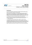
Figure 6.
MPPT - maximum power point algorithm
250W microinverter - firmware flow chart
-AIN
HW?CONFIGC
s2##?#ONFIG
s.6)#?#ONFIGURATION
s'0)/?#ONFIGURATION
s3YS4ICK?#ONFIG
s)NIT#ONTROL#LOSED,OOP
s34-%?,#$?)NIT
3ET3YSTEM
7AITINGFOR
*OYSTICKEVENT
RIGHTLEFTDOWN
UPCENTER
/PENLOOP
-AINC
7HILE
[
]
/PENLOOP OR
#LOSEDLOOP
SELECTED
#LOSEDLOOP
3TART#ONTROL
3TARTCOMMANDSENT
$ATA3ENSINGENABLED
.OPROTECTIONSENABLED
)N$#$#SECTIONTHE07-S
AREREGULATEDATFIXEDDUTYCYCLE
MODIFIABLEBY,#$
)N$#!#SECTIONTHE07-S
ARECONTROLLEDBYLOOKUPTABLE
-AINFUNCTION
%XEC#ONTROL
3TART#ONTROLIN
OPENLOOPMODE
$IAGNOSTICMODE
/UTOFRANGE
$IAGNOSTIC
!#LINE
6ACMIN6!#RMS6ACMAX
&REQ?MIN®?GRID&REQ?MAX
%XEC#ONTROL/PEN
,OOP
/UTOFRANGE
$#$#$#!#
CONVERTERSSTARTED
$IAGNOSTIC
$#LINE
06VOLT?MIN06?VOLTAGE0VVOLT?MAX
34/0
"5302%#(!2'%
9%3
0ROTECTIONS
REQUESTED
)NRUSHCONTROLSTARTED
./
34!24
'2)$).3%24)/.
0RE'RID)NSERTIONCONTROL
7#ONVERTERC
!-V
Doc ID 023556 Rev 1
35/39
Input/output protection
11
UM1561
Input/output protection
The power board is also controlled by the microcontroller for the input/output protection.
During normal operation it is possible that the cables (input or output side) are accidentally
disconnected from the panel or from the grid. In this case, overcurrent or overvoltage may
appear at the power stage. To avoid damaging the electronic parts, a procedure is
implemented in the 250WControl.c file, as follows:
if (BusFiltered > 13000)
{
Fault = BUS_OVERVOLTAGE;
GPIO_ResetBits(GPIOA, GPIO_Pin_1);
State_Control = STOP_WITH_DELAY;
Diagnostic_Control=BUS_OVERVOLTAGE;
}
if (BusFiltered < 9880 && MPPT_EN==TRUE)
{
Fault = BUS_UNDERVOLTAGE;
GPIO_ResetBits(GPIOA, GPIO_Pin_1);
State_Control = STOP_WITH_DELAY;
Diagnostic_Control=BUS_UNDERVOLTAGE;
}
where:
●
Fault = BUS_OVERVOLTAGE; is (Bus overvoltage detected)
Fault = BUS_UNDERVOLTAGE; is (Bus undervoltage detected).
●
if((qIalpha_Inverter > 19667 || qIalpha_Inverter <-19667) &&
State_Control==GRID_INSERTION && MPPT_EN==TRUE) //1.6 max output peak
current
{
Fault = OUT_CURRENT_LIMIT;
GPIO_ResetBits(GPIOA, GPIO_Pin_1);
State_Control = STOP_WITH_DELAY;
Diagnostic_Control=OUT_CURRENT_LIMIT;
}
where:
●
GPIO_ResetBits(GPIOA, GPIO_Pin_1); is (AC line overcurrent detected)
State_Control = STOP_WITH_DELAY; is (PV_module Vmin detected).
●
if(PV_Voltage<=11000 && State_Control==GRID_INSERTION) //22V min
{
GPIO_ResetBits(GPIOA, GPIO_Pin_1);
State_Control = STOP_WITH_DELAY;
Diagnostic_Control=PV_VOLTAGE_MIN;
}
36/39
Doc ID 023556 Rev 1
UM1561
Input/output protection
When a bus over/undervoltage, overcurrent or minimum input voltage appears, the closed
loop control stops the MPPT function and it moves to the next state machine
(STOP_WITH_DELAY). At this point, the power board is waiting for a physical opening of
the relay. During the fixed time (10 msec) the PWM continues to modulate at the DC-DC
stage and the DC-AC stage. At the end of this period, they all switch off. This time is in
accordance with the relay specifications.
Doc ID 023556 Rev 1
37/39
Revision history
12
UM1561
Revision history
Table 1.
38/39
Document revision history
Date
Revision
16-Oct-2012
1
Changes
Initial release.
Doc ID 023556 Rev 1
UM1561
Please Read Carefully:
Information in this document is provided solely in connection with ST products. STMicroelectronics NV and its subsidiaries (“ST”) reserve the
right to make changes, corrections, modifications or improvements, to this document, and the products and services described herein at any
time, without notice.
All ST products are sold pursuant to ST’s terms and conditions of sale.
Purchasers are solely responsible for the choice, selection and use of the ST products and services described herein, and ST assumes no
liability whatsoever relating to the choice, selection or use of the ST products and services described herein.
No license, express or implied, by estoppel or otherwise, to any intellectual property rights is granted under this document. If any part of this
document refers to any third party products or services it shall not be deemed a license grant by ST for the use of such third party products
or services, or any intellectual property contained therein or considered as a warranty covering the use in any manner whatsoever of such
third party products or services or any intellectual property contained therein.
UNLESS OTHERWISE SET FORTH IN ST’S TERMS AND CONDITIONS OF SALE ST DISCLAIMS ANY EXPRESS OR IMPLIED
WARRANTY WITH RESPECT TO THE USE AND/OR SALE OF ST PRODUCTS INCLUDING WITHOUT LIMITATION IMPLIED
WARRANTIES OF MERCHANTABILITY, FITNESS FOR A PARTICULAR PURPOSE (AND THEIR EQUIVALENTS UNDER THE LAWS
OF ANY JURISDICTION), OR INFRINGEMENT OF ANY PATENT, COPYRIGHT OR OTHER INTELLECTUAL PROPERTY RIGHT.
UNLESS EXPRESSLY APPROVED IN WRITING BY TWO AUTHORIZED ST REPRESENTATIVES, ST PRODUCTS ARE NOT
RECOMMENDED, AUTHORIZED OR WARRANTED FOR USE IN MILITARY, AIR CRAFT, SPACE, LIFE SAVING, OR LIFE SUSTAINING
APPLICATIONS, NOR IN PRODUCTS OR SYSTEMS WHERE FAILURE OR MALFUNCTION MAY RESULT IN PERSONAL INJURY,
DEATH, OR SEVERE PROPERTY OR ENVIRONMENTAL DAMAGE. ST PRODUCTS WHICH ARE NOT SPECIFIED AS "AUTOMOTIVE
GRADE" MAY ONLY BE USED IN AUTOMOTIVE APPLICATIONS AT USER’S OWN RISK.
Resale of ST products with provisions different from the statements and/or technical features set forth in this document shall immediately void
any warranty granted by ST for the ST product or service described herein and shall not create or extend in any manner whatsoever, any
liability of ST.
ST and the ST logo are trademarks or registered trademarks of ST in various countries.
Information in this document supersedes and replaces all information previously supplied.
The ST logo is a registered trademark of STMicroelectronics. All other names are the property of their respective owners.
© 2012 STMicroelectronics - All rights reserved
STMicroelectronics group of companies
Australia - Belgium - Brazil - Canada - China - Czech Republic - Finland - France - Germany - Hong Kong - India - Israel - Italy - Japan Malaysia - Malta - Morocco - Philippines - Singapore - Spain - Sweden - Switzerland - United Kingdom - United States of America
www.st.com
Doc ID 023556 Rev 1
39/39