1
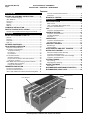
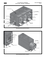
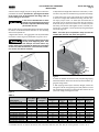
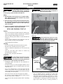
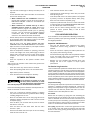
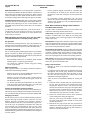
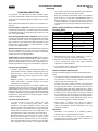
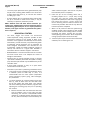
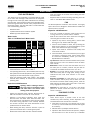
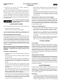
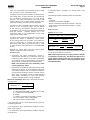
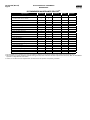
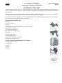
Form 140.920-IOM (NOV 2009) INSTALLATION - OPERATION - MAINTENANCE File: Replaces: Dist: SERVICE MANUAL - Section 140 NOTHING 3, 3a, 3b, 3c XLP2 Evaporative Condenser THIS MANUAL CONTAINS RIGGING, ASSEMBLY, START-UP, AND MAINTENANCE INSTRUCTIONS. READ THOROUGHLY BEFORE BEGINNING INSTALLATION. FAILURE TO FOLLOW THESE INSTRUCTIONS COULD RESULT IN DAMAGE OR IMPROPER OPERATION OF THE UNIT. Please check www.johnsoncontrols.com for the latest version of this publication. 140.920-IOM (NOV 09) Page 2 XLP2 EVAPORATIVE CONDENSERS INSTALLATION - OPERATION - MAINTENANCE Contents INSTALLATION RIGGING AND ASSEMBLY INSTRUCTIONS............... 4 Check Unit Before Rigging...................................................4 UNIT WEIGHTS....................................................................4 Anchoring............................................................................4 Leveling...............................................................................4 Rigging................................................................................4 Table 1................................................................................. 5 FLUME BOX INSTALLATION..................................... 6 POSITIVE CLOSURE PLATE OPTION..........................7 Positive Closure Plate Installation (Figures 11 and 12):......... 7 OPERATION INITIAL AND SEASONAL START-UP........................ 8 General................................................................................8 Cleaning...............................................................................8 Inspection............................................................................8 Start-up...............................................................................8 EXTENDED SHUTDOWN........................................... 9 COLD WEATHER OPERATION................................... 9 Inspection and Maintenance................................................9 Fan Section Icing Protection................................................9 Temperature Setting........................................................9 Fan Control......................................................................9 Dry Operation................................................................10 Coil Freeze Protection.......................................................10 Minimum Operation.......................................................10 Positive Closure Damper Hood and Insulation................10 Emergency Coil Drain.....................................................10 Basin Water and Internal Piping Freeze Protection............ 10 Cold Water Basin Protection..........................................10 Piping Freeze Protection................................................10 CORROSION PROTECTION......................................11 Corrosion and Treatments................................................. 11 Corrosion and Scale Control.............................................. 11 Table 2: Quality Guidelines for Chemically Treated Circulating Water..... 11 Chemical Treatment Requirements.................................... 11 Passivation........................................................................ 11 BIOLOGICAL CONTROL...........................................12 MAINTENANCE COLD WATER BASIN..............................................13 Water Levels...................................................................... 13 Table 3: Cold Water Basin Water Levels............................ 13 Inspection and Maintenance.............................................. 13 FAN........................................................................13 Inspection and Maintenance.............................................. 13 FAN DRIVE SYSTEM...............................................13 Inspection and Maintenance.............................................. 13 Fan Belt Adjustment:......................................................... 14 Alignment:......................................................................... 14 FAN MOTORS.........................................................14 Inspection and Maintenance.............................................. 14 Adjustable Motor Base...................................................... 14 FAN SHAFT SUPPORTS .........................................15 Ball Bearings...................................................................... 15 Locking Collars.................................................................. 15 SPRAY NOZZLES AND HEAT TRANSFER.................15 WATER LEVEL CONTROL........................................16 Mechanical Makeup Valve Assembly.................................. 16 Inspection and Maintenance:............................................. 16 Optional Electric Water Level Control Package.................. 16 Inspection and Maintenance:............................................. 16 SYSTEM CLEANING................................................16 Coil Cleaning...................................................................... 16 Weld Byproduct Cleaning.................................................. 16 WATER TREATMENT..............................................16 Bleed Rate......................................................................... 16 RECOMMENDED MAINTENANCE SERVICES(1)............ 18 RECOMMENDED SPARE PARTS..............................19 Spray Branches Drift Eliminators Casing Coil XLP2 Evaporative Condenser Heat Transfer Coil Section XLP2 EVAPORATIVE CONDENSERS INSTALLATION - OPERATION - MAINTENANCE 140.920-IOM (NOV 09) Page 3 Plenum Partition Two-Stage Axial-Flow Fan Fan Ball Bearing Access Door Fan Screen Water Bleedline Fan Drive Step Water Makeup Valve Assembly Fan Motor Strainer Spray Pump Adjustable Float Motor Base Adjustment Fan Shaft XLP2 Side Discharge Evaporative Condenser Water Makeup Valve Assembly Adjustable Float Strainer Two-Stage Axial-Flow Fan Fan Ball Bearing Water Bleedline Spray Pump Access Door Fan Shaft Motor Base Adjustment XLP2 End Discharge Evaporative Condenser Fan Drive Fan Motor 140.920-IOM (NOV 09) Page 4 XLP2 EVAPORATIVE CONDENSERS INSTALLATION INSTALLATION INTRODUCTION XLP2 units should be rigged and assembled as outlined in this bulletin. These procedures should be thoroughly reviewed prior to the actual rigging operation to acquaint all personnel with procedures to be followed and to assure that all necessary equipment will be available at the jobsite. Locate the unit nameplate on the connection end of the unit and record the unit serial number and model number for reference. Have a copy of the unit certified drawing available for reference. If you do not have a copy of this drawing, contact your local Representative. RIGGING AND ASSEMBLY INSTRUCTIONS Check Unit Before Rigging When the unit is delivered to the jobsite, check it thoroughly to ensure all required items have been received and are free of any shipping damage before signing the bill of lading. The following parts should be inspected: Sheaves and Belts Bearings Bearing Supports Fan Motor(s) Fan(s) and Fan Shaft(s) Coils Interior/Exterior Surfaces Eliminators Float Valve Assembly Strainer(s) Water Distribution System Miscellaneous Items: If required for field assembly, the following parts will be packaged and usually placed inside the basin-fan section: Sealer, Self-Tapping Screws, and Accessory Items. A checklist inside the envelope attached to the side of the unit marked “Contractor’s Installation Instructions” indicates what miscellaneous parts were included with the shipment and where they were packed. Be sure to remove all accessory items from the basin before the unit is assembled. UNIT WEIGHTS Before rigging any XLP2 Product, the weight of each section should be verified from the unit certified drawing. Some accessories add aditional weight as shown on the respective accessory drawings. These weights are approximate only and should be confirmed by weighing before lifting when available hoisting capacity provides little margin for safety. In preparing for a lift, individuals responsible for rigging Frick units must inspect the equipment before the lift to make certain that all water or other liquids have been drained from the unit and any debris removed. During cold weather, the pre-lift procedure must include a check for and removal of accumulations of ice and snow, which will not naturally drain from the equipment and would add substantially to the equipment’s lifting weight. Anchoring Unit must be properly anchored in place before operation begins. Seven-eighths inch (7/8”) diameter bolt holes are provided in the bottom flange of the basin section for bolting the unit to the support beams. Refer to the suggested support details on the certified drawing for locations of the mounting holes. Anchor bolts are supplied by others. Leveling The support beams and unit must be level for proper operation. Shims should not be used between the basin and support beams to level the unit. Operation, maintenance, and repair of this equipment should be undertaken only by personnel qualified to do so. Proper care, procedures and tools must be used in handling, lifting, installing, operating, maintaining and repairing this equipment to prevent personal injury and/or property damage. Adequate precautions, appropriate for the installation and location of these products, should be taken to safeguard the public from possible injury and the equipment and the premises from damage. Solid bottom panels may be desirable or necessary for safety and other reasons depending on the location and conditions at the installation site. PVC eliminators on this product are not designed to support the weight of a person or to be used as a storage or work surface for any equipment or tools. Use of these plastic eliminators as walking, working or storage surface may result in injury to personnel or damage to equipment. If covering a unit which has PVC eliminators, do not use a clear plastic tarpaulin. For a discussion of Safety Precautions to be followed when operating or maintaining this equipment, please refer to the Operation and Maintenance Sections of this manual. WARRANTIES—Please refer to the Limitation of Warranties applicable to and in effect at the time of the sale/purchase of these products. FREEZE PROTECTION—These products must be protected by mechanical and operational methods against damage and/or reduced effectiveness due to possible freeze-up. Please refer to the Operation and Maintenance sections of this Manual or contact the local Frick Representative for recommended protection alternatives. Rigging To simplify rigging and installation, most XLP2 Series Units are shipped in sections consisting of the basin and casing sections. The basin and casing components must be rigged separately. Never assemble the unit before lifting as the lifting devices provided are not designed to support the weight of the entire assembled unit. The proper rigging sequence is to lift the basin section into place, apply sealer to the basin where the casing(s) will be located, XLP2 EVAPORATIVE CONDENSERS INSTALLATION and then lift the casing(s) into place. Lifting devices have been provided on all sections. Spreader bars, spanning the full width of the section, must be used between the lifting cables to prevent damage to the section. In the event of extended lifts or where hazards exist, the lifting devices should be used in conjunction with safety slings placed under the unit. Refer to Table 1 for the recommended minimum size of the spreader bar and the recommended vertical dimension “H” from the lifting device to the spreader bar. 1. Rig the basin section. The rigging hook must be placed above the section’s center of gravity as detailed in Figures 1 and 2. 140.920-IOM (NOV 09) Page 5 2. Wipe down the flanges with acetone to remove dirt, or moisture which may have accumulated during shipment and storage. 3. Install sealer tape on the mating flange of the basin section to ensure an airtight seal between the casing and basin section. Apply a layer of 1/4” x 1” sealer tape around the face of the flange over the centerline of the holes. Do not overlap or stretch too thinly at the corners. When it is necessary to splice the sealer, press the two ends together to form a smooth, continuous strip. The sealer is to be spliced only along the flanges with holes (Figure 3). NOTE: The sealer tape is trapezoidal in shape and must be installed with the wide side down (see Figure 4). Before proceeding, bolt the basin section securely to the supporting steel. Units with multiple cold water basins may employ flume boxes to equalize the water level in the basin of each cell. Follow the directions in the Flume Box Installation section (see Table of Contents). “L” “H” “L” “H” Center of Gravity Figure 2 Center of Gravity 4. Lower the flexible connection on the pump discharge piping below the elevation of the basin section top section before rigging the casing section. 5. After applying sealer tape to the basin flanges, remove the casing skid. Lift the casing (see Figure 6) and position it so that the casing flanges are about 2” above the basin section. Do not permit the casing to damage the sealer. Figure 1 Table 1 Model Number XLP2-512-130 to 512-203 XLP2-712-164 to 712-276 XLP2-812-235 to 812-343 XLP2-818-320 to 818-474 XLP2-1012-282 to 1012-545 XLP2-1018-433 to 1018-829 XLP2-1024-564 to 1024-1089 * XLP2-1036-866 to 1036-1658 XLP2-1012-282 to 1012-545 XLP2-1218-495 to 1218-1075 XLP2-1224-644 to 1224-1405 ** XLP2-1236-989 to 1236-2148 No. of Basin Sections No. of Casing Sections 1 1 1 1 1 1 2 2 1 1 2 2 1 1 1 1 1 1 2* 2 1 1 2 ** 2 Basin Section Spreader Bar Length “L” 5' 6' 8' 8' 10' 10' 10' 10' 12' 12' 12' 12' Minimum Height “H” 10' 5" 10' 5" 10' 5" 15' 7" 10' 5" 15' 7" 10' 5" 15' 7" 10' 5" 15' 7" 10' 5" 15' 7" Casing Section Center of Gravity 2B\," 3¼" 3M\," 3M\," 6C\," 6C\," 6C\," 6C\," 7C\," 7C\," 7C\," 7C\," Spreader Bar Length “L” 5' 6' 8' 8' 10' 10' 10' 10' 12' 12' 12' 12' Minimum Height “H” 8' 10" 8' 10" 8' 10" 8' 10" 8' 10" 8' 10" 8' 10" * 8' 10" 8' 10" 8' 10" 8' 10" ** 8' 10" * For Models 1024-660, 668, 706, 745, 756, 799, 822, 833, 879, 881, 892, 940, No. of Casing sections = 1 and H = 12' 4". ** For Models 1224-743, 775, 812, 876, 917, 965, 992, 1012, 1034, 1064, 1084, 1090, 1139, 1196, 1281, No. of Casing sections = 1 and H = 12' 4". 140.920-IOM (NOV 09) Page 6 XLP2 EVAPORATIVE CONDENSERS INSTALLATION Splice Sealer Tape Along Flanges With Bolt Holes rate is automatically controlled by a water treatment system. See Bleed Rate section under Water Treatment at the end of the MAINTENANCE section. Figure 5 Figure 3 6. Insert drift pins downward through the four corner screw holes in the casing (Figure 5). Continue to lower the casing slowly, maintaining alignment with the drift pins until it rests on the basin section. “L” “H” Figure 6 FLUME BOX INSTALLATION (Required for Models XLP2-1024-xxxx, -1224-xxxx, -1036xxxx, and -1236-xxxx) Figure 4 7. Working from the corners towards the center, install the 3/8” bolts, using the drift pin to align the screw holes. 8. Secure the hose connecting the sections of the pump discharge pipe with the hose clamps provided. 9. On units with more than one casing, install the remaining casings using the same procedure as the first. When installing two or more casings, on the basin section, sealer tape must be applied to both cross flanges. (Figure 3) 10. On units operating with a remote sump tank, install a bleed line with valve between the system circulating pump discharge riser and a convenient drain. Locate the bleed line in a portion of the riser piping that drains when the pump is off. Units that are furnished with a factory-installed circulating pump include a bleed line with valve. Bleed valves should remain open when the unit is in operation, unless the bleed 1. Position Cell #1 on the unit support and bolt in place. 2. Wipe down the mating surface by the flume opening to remove any dirt or moisture that may have accumulated during shipment. 3. Wipe down the flanges on both ends of the flume box. On one end, apply a layer of 1/8” x 1” butyl sealer tape around the face of the flange over the centerline of the holes. Do not overlap or stretch too thinly at the corners. When it is necessary to splice the sealer, be sure to press the two ends together to form a smooth, continuous strip. Apply a second layer of sealer tape over the first layer following the same procedure. Refer to Figure 8. 4.Using drift pins to align the bolt holes, place the flume box over the opening in the basin of Cell #1 and fasten into place. Insert the 3/8” self-tapping screws or bolts from the flume box into the basin wall as illustrated in Figure 9 . NOTE: Flume boxes furnished with units constructed with stainless steel basins are assembled with stainless steel bolts, washers and nuts in lieu of self-tapping screws. XLP2 EVAPORATIVE CONDENSERS INSTALLATION 5. Apply sealer to the other end of the flume box as described in Step 3. 140.920-IOM (NOV 09) Page 7 NOTE: Units equipped with the positive closure plate option, skip step 8 and go to the positive closure plate section of this document. 8. As illustrated in Figures 9 and 10, insert 3/8” self-tapping screws in each hole from the flume box into the basin wall and tighten. POSITIVE CLOSURE PLATE OPTION The optional Positive Closure Plate and gasket are furnished on multicell units to allow individual cells to be isolated for cleaning and maintenance. The plate ships loose inside the basin. To install the Positive Closure Plate and gasket, follow the steps from the Flume Box Installation section, then complete the installation using the instructions listed. Positive Closure Plate Installation (Figures 11 and 12): Figure 7 6. Position Cell #2 on the unit supports, exactly 1” between basins (Figure 7). Wipe down the mating surface by the flume opening to remove any dirt or moisture. 1. Thread 3/8” self-tapping screws from the flume box into the basin wall with the positive closure plate as shown. 2. Position gasket and positive closure plate over the bolts and fasten in place with 3/8” wing nut and flat washers. 7. Using drift pins to ensure alignment, draw Cell #2 tight against the flume box. Figure 8 Figure 9 Figure 10 Figure 11 Figure 12 140.920-IOM (NOV 09) Page 8 XLP2 EVAPORATIVE CONDENSERS OPERATION OPERATION Do not perform any service on or near the fans, motors, drives, or inside the unit without first ensuring that the fans and the pumps are disconnected and locked out. Check to ensure the controls for the fan motors are set to allow a maximum of 6 on-off cycles per hour. NOTES: 1. Recommended service intervals are for typical installations. Different environmental conditions may dictate more frequent servicing. 2. When operating in ambient temperatures below freezing, the unit should be inspected more frequently. Refer to “Cold Weather Operation” section for more details (see Table of Contents). 3. Tension on new belts must be readjusted after the first 24 hours of operation and quarterly, thereafter. INITIAL AND SEASONAL START-UP General • If the unit is mounted on vibration isolators or isolation rails, refer to the vibration isolation manufacturer’s guidelines before loading/unloading weight from the unit. • Verify fan and spray pump motors are disconnected and locked out. • Conduct external inspection of the equipment. Check for leaks, corrosion, and any structural damage. • Inspect piping and connections. Figure 13 - Water Makeup Valve Assembly Start-up Do not perform any service on or near the fans, motors, and drives, or inside the unit without first ensuring that the fans and the pumps are disconnected and locked out. Cleaning • Drain the cold water basin with the strainers in place. • Remove all dirt and debris from the fan guards. • Clean all mechanical components, such as the fans and motors. • Flush the cold water basin interior to remove any accumulated dirt and debris. • Remove, clean, and replace the strainers. J-Bolts Inspection Do not perform any service on or near the fans, motors, drives, or inside the unit without first ensuring that the fans and the pumps are disconnected and locked out. • Thoroughly inspect the fan(s) for any mechanical or physical damage. • At seasonal start-up or after prolonged shutdown, check the motor insulation with an insulation tester prior to the motor start-up. • Prior to the seasonal tension. At the initial require adjustment as at the factory prior to start-up, check and adjust the belt start-up, the belt tension may not the drive will be properly tensioned shipment. • Start the fan motors and check for proper fan rotation. • Run the fans in manual mode for several minutes to check for any unusual noise or vibrations. • Check that the float-operated makeup valve is operating freely. Locking Nuts (Typical of Both Sides) Adjusting Screw Figure 14 - Lubricating Motor Base Adjusting Screws • Prior to seasonal start-up, lubricate the motor base adjusting screws and the fan shaft bearings. Then coat the motor base slides and adjusting screws every 3 months using good quality corrosion inhibiting grease such as one recommended for lubricating the fan shaft bearings (see Figure 14). At initial start-up, no bearing lubrication is XLP2 EVAPORATIVE CONDENSERS OPERATION required since the bearings are factory lubricated prior to shipment. • Fill the cold water basin with fresh water to the overflow level via the makeup valve. 1. Water treatment for new installations: Initiate the biocide water treatment program at this time. Refer to BIOLOGICAL CONTROL section for more details (see Table of Contents). 2. Water treatment for seasonal start-up or after a shutdown period in excess of 3 days: Resume the biocide treatment program and administer a shock treatment of appropriate biocides prior to operating the fans. This will eliminate accumulated biological contaminants. Refer to the BIOLOGICAL CONTROL section for more details (see Table of Contents). • Set the makeup valve to shut off below the top of the basin at the operating water levels stated in Table 3 in the COLD WATER BASIN section under MAINTENANCE. • Start the spray pump. See SPRAY NOZZLES AND HEAT TRANSFER section under MAINTENANCE for more details. • Open the valve in the unit bleed line, and adjust the bleed by closing or opening the valve. • • • Clean the basin strainer and re-install. • Lubricate the fan shaft bearings, motor base, and motor base adjusting screw. • Close the shutoff valve in the makeup water line (supplied by others), and drain all exposed makeup water piping. Heat trace and insulate all exposed piping. • Inspect the protective finish on the unit. Clean and refinish as required. Refer to the CORROSION PROTECTION section for more details (see Table of Contents). • Secure the fan motors starting device(s) in the “OFF” position to ensure personal safety in case of future inspection or service. COLD WEATHER OPERATION Frick condensers can be operated at subfreezing ambient temperatures provided proper operating methods are established and diligently followed. Inspection and Maintenance • Carry out the frequent visual inspections and routine maintenance services during operation in subfreezing weather. Once the evaporative condenser is operating, check the current and voltage of all three phases (legs) of the fan motors with a heat load on the unit under warm ambient conditions. The current must not exceed the nameplate ratings. • Ensure all controls for capacity and freeze protection are set properly and functioning normally. • Prevent excessively high water levels and possible overflow of the cold water basin due to overpumping, clogged strainers, or makeup valve malfunction. Check the operation of the optional vibration cutout switch. • Resolve any icing condition that develops which may damage the unit or the supports or impair system performance. After 24 hours of operation under thermal load, perform the following services: • Check the unit for any unusual noise or vibrations. • Check the operating water level in the cold water basin. • Adjust makeup valve if necessary. • Check the belt tension and readjust if necessary. EXTENDED SHUTDOWN Do not perform any service on or near the fans, motors, and drives, or inside the unit without first ensuring that the fans and the pumps are disconnected and locked out. Perform the following services whenever the evaporative condenser is shut down in excess of 3 days: • 140.920-IOM (NOV 09) Page 9 If the unit is mounted on vibration isolators or isolation rails, refer to the manufacturer’s guidelines before loading/ unloading weight from the unit. • Drain the cold water basin and all the piping that will be exposed to freezing temperatures. Heat trace and insulate all exposed piping. • Clean all debris, such as leaves and dirt, from the interior and exterior of the unit. • Clean and flush the cold water basin with the basin strainers in place. • Leave the cold water basin drain open so rain and melting snow will drain from the unit. Fan Section Icing Protection There are three basic operational methods which can be used to provide the system’s required cooling: Temperature Setting, Fan Control, and Dry Operation. The method of controls employed on a given application depends upon the climatic extremes which are expected, the variations in heat load that will be encountered, and the compatibility of the control system with other portions of the installation. Effective icing control in subfreezing ambient conditions will require a combination of these three methods. Temperature Setting Low leaving fluid temperature promotes ice formation. During operation in subfreezing ambient temperatures, maintain the leaving fluid temperature as high as possible. Ensure the unit operates with the maximum possible heat load. The recommended minimum fluid temperature is 45°F. Fan Control Reduce the unit capacity by cycling fans thus modulating the airflow through the unit. Rapid on-off cycles can cause the fan motor to overheat. Set the controls to allow a maximum of 6 on-off cycles per hour. Periodically, cycle the fans off to prevent ice formation and/or to melt ice that accumulates on the intake louvers or combined inlet shields and face of the fill. Fan Cycling: Operate each unit with the highest thermal load it can handle, rather than evenly dividing the total heat load across all cells. During prolong periods, bypass the idle units and drain the basins. 140.920-IOM (NOV 09) Page 10 XLP2 EVAPORATIVE CONDENSERS OPERATION Multi-Speed Motors: If the unit is equipped with 2-speed motors or Sentinel™/Sentinel PLUS™ Fan System, operation at a lower speed may be sufficient to prevent icing. When 2-speed motors are used, the motor starter should include a minimum 15 second time delay when switching from high to low speed. Variable Frequency Drives: VFDs offer the most precise method of capacity control, by modulating fan motor speed. When using VFDs, avoid operating at or near “critical speeds.” Units with VFDs require inverter duty motors which are included as standard. In subfreezing ambient temperatures, cycle the fan off for 5 minutes every 15 to 20 minutes for each cell. If ice continues to build on the louvers, decrease the on-time. Observe inlet louvers every 4 to 8 hours. • Further protection against coil freeze-up is possible with the installation of an alarm to alert personnel when the temperature of the fluid leaving the coil falls below 50°F (10°C). • For evaporative cooling applications only, the glycol solution will maintain the leaving fluid temperature as low as 45°F (7.2°C). Contact your local Frick Representative for necessary precautions. Basin Water and Internal Piping Freeze Protection Cold Water Basin Protection The basin water could freeze when the unit is shut down and exposed to subfreezing ambient temperatures. NOTE: Modulating the water flow rate to the unit is NOT a recommended method of controlling cooling capacity. Indoor Sump: The ideal method of protection is a remote sump located in a heated indoor area. When the circulating pump stops, the water in the connecting piping will drain by gravity to this indoor sump. Dry Operation One method of protecting fans from icing is dry operation. Dry operation of the evaporative condenser protects fans from ice formation due to mist and splash from the cold water basin. Basin Heaters: On applications without a remote sump, provide heat to the cold water basin. Electrical immersion heaters, steam coils or hot water coils can provide the required function. Contact your local Frick Representative for details. Coil Freeze Protection Electric Water Level Control: An electric water level control will maintain the proper water level regardless of the thermal load or variations in makeup water supply pressure. The two-position, slow closing solenoid valve provided in the Frick electric water level control package also minimizes valve freezing problems. Use an industrial grade inhibited glycol solution for protection against coil freeze-up. When the use of glycol is not practical, the system must be designed to meet both minimum flow and minimum temperature requirements. • Recommended solutions are an industrial grade inhibited ethylene glycol or propylene glycol solution. • Coil volume for condenser models using liquid cooling circuits is job specific. Minimum Operation When a glycol solution is not utilized, operate the system to meet both of the following conditions. • Maintain the minimum recommended flow through the coil at all the times per the job specifications. • Maintain a minimum heat load on the circulating fluid so that the temperature of the fluid leaving the coil will not fall below 50°F (10°C). • To maintain the leaving fluid temperature at 50°F (10°C) when the process load is extremely light or shut off, apply an auxiliary heat load to the circulating fluid. Positive Closure Damper Hood and Insulation The amount of auxiliary heat required can be substantially reduced by the use of a positive closure damper hood and insulation. The heat loss data can be found in publication 140.920-SED. Emergency Coil Drain Do not drain the coil as a normal method of freeze protection. Frequent draining promotes corrosion inside the coil tube. However, draining is acceptable as an emergency method of freeze protection if the coil is not protected by a glycol solution. If the coil is not protected, an automatic drain valve and vacuum breaker are recommended to drain the coil if flow stops or fluid temperature drops below 50°F (10°C) when the ambient temperature is below freezing. Contact your local Frick Representative for guidelines on the installation of an emergency coil drain system. Heat Tracing: Heat trace and insulate all exposed water piping, including pump piping below the overflow level and makeup water lines, with electrical heater tape. Piping Freeze Protection • Eliminate all water in the optional SmoothLink™ Piping Arrangement. • It is essential to drain water from the SmoothLink™ Piping Arrangement and internal piping whenever the potential for freezing temperatures exits. Drain the water by using 1/2” NPT drain port located on the inboard side of the SmoothLink™ Piping Arrangement. • There are three recommended methods for draining the piping: 1. Preferred: Install a normally open 1/2” solenoid valve on the 1/2” drain connection of the SmoothLink™ Piping Arrangement. Wire the valve in the pump circuit such that the valve closes when the pump is energized. Select the solenoid valve to operate with a minimum pressure differential of 0 psi, which is required to limit the static head imposed on the valve from the water column. 2. Install a 1/2” manual valve on the 1/2” drain connection of the SmoothLink™ Piping Arrangement. Open the valve during cold weather operation. Keep the valve closed during warm weather to achieve full thermal performance. 3. Remove the 1/2” plug from the 1/2” drain connection of SmoothLink™ Piping Arrangement during cold weather operation. Reinstall the plug during warm weather to obtain full thermal performance. XLP2 EVAPORATIVE CONDENSERS OPERATION CORROSION PROTECTION Frick products are constructed of corrosion-resistant materials. The fill (if applicable) is made of a polyvinyl chloride (PVC), which requires no protection against rot, decay, rust or biological attack. are necessary, which raise the allowable level of dissolved solids without the risk of scale and corrosion. • Other materials listed below are used in the equipment construction: Galvanized Steel Components: Inspect the galvanized steel components for blemishes or corrosion. Wire brush and recoat the affected areas with a cold galvanizing compound such as zinc rich compound (ZRC). Thermosetting Hybrid Polymer Components: Galvanized steel components protected with the Thermosetting Hybrid Polymer may develop scratches, scrapes or blemishes. Touch up these with a repair kit. In the unlikely event that the damage is more extensive than simple scratches or minor blemishes, contact your local Frick Representative. Stainless Steel Components: Inspect stainless steel components for signs of blemishes or corrosion. Clean with stainless steel wool as necessary. If more extensive corrosion is prevalent, contact your local Frick Representative. TripleGuard™ Corrosion Protection System: Inspect components protected with the TripleGuard™ Corrosion Protection System for signs, deep scratches or blemishes, especially in areas with field penetrations. Touch these up with either rubberized polyurethane caulking such as Vulkem® or a repair kit. 140.920-IOM (NOV 09) Page 11 Keep the chemically treated water within the guidelines given in Table 2. In cases where bleed/blowdown alone is being employed for corrosion and scale control, without chemical treatment, your water treatment specialist may recommend more conservative limits than those shown in Table 2. Table 2: Quality Guidelines for Chemically Treated Circulating Water Property of Water Recommended Level pH Hardness as CaCO3 Alkalinity as CaCO3 Total Dissolved Solids (TDS) Conductivity Chlorides 6.5 to 9.0(1) 30 to 750 ppm(2) 500 ppm maximum(2) 1500 ppm maximum 2400 micromhos(3) 250 ppm maximum Cl (410 ppm maximum as NaCl) 250 ppm maximum 150 ppm maximum Sulfates Silica NOTES: 1. Galvanized steel units require passivation in order to prevent white rust (refer to passivation below). 2. Hardness and alkalinity limits may be exceeded under certain circumstances. Consult your water treatment specialist for recommendations. Corrosion and Treatments 3. The conversion factor used to determine conductivity is 0.625 (TDS = 0.625 x Conductivity). • Corrosion – Red rust on steel components and “white rust” on galvanized surfaces will affect the longevity of the unit. Chemical Treatment Requirements • Scale Formation – Scale not only reduces heat transfer and system efficiency, but also may lead to under deposit corrosion. • Biological Fouling – Slime and algae formations may reduce heat transfer, promote corrosion, and harbor pathogens such as Legionella. Chemical treatment programs must meet the following requirements: • The chemicals must be compatible with the unit materials of construction as well as other materials used in the system (pipe, heat exchanger, etc.). • Chemical scale and corrosion inhibitors, particularly acid (if used), should be introduced into the circulating water through automatic feeders. This should be done at a point in the system where total mixing and dilution occur, before reaching the evaporative cooling equipment. The preferred injection point for chemical scale and corrosion inhibitors is on the discharge side of the system circulating pump(s). These chemicals should not be batch fed directly into the unit’s cold water basin or water distribution system, as this can severely damage areas directly contacted. • When chlorine is added to the system, free residual chlorine should not exceed 1 ppm, except as noted in start-up and shutdown section. Exceeding this limit may accelerate corrosion. Since the quality of the ambient air and makeup water varies significantly from job site to job site, Frick strongly recommends obtaining the services of a competent water treatment specialist prior to the initial start-up of the evaporative cooling equipment. Additionally, to protect against the risk of Legionella contamination, never operate the cooling equipment without adequate biological control. Corrosion and Scale Control • • To control corrosion and scale, maintain the water chemistry of the recirculating water within certain parameters. The specific measures required vary from system to system and are dependent on the chemistry of the makeup water, the metallurgy of the piping and heat transfer devices exposed to the recirculating water, and the temperatures at which the system will be operating. Bleed/blowdown, the continuous flow of a small portion of the recirculating water to a drain, is used to control the concentration of dissolved solids. On rare occasions, this may be adequate to control scale and corrosion. More often, however, chemical scale and corrosion inhibitors Passivation • Passivation is the formation of a protective, passive, carbonate layer on galvanized steel surfaces. • On the newly installed units, to provide maximum protection from corrosion, take special measures to passivate galvanized steel surfaces. 140.920-IOM (NOV 09) Page 12 • • XLP2 EVAPORATIVE CONDENSERS OPERATION To ensure proper passivation of the galvanized steel, keep the pH of the circulating water between 7.0 to 8.2 for four to eight weeks after start-up, or until new zinc surfaces turn dull gray in color. water treatment supplier. Start the fan only after this treatment period is completed. b. Check the pH of the circulating water and, if necessary, adjust it to 7.0 - 7.6 pH. Then, running the pump only, treat the system with sodium hypochlorite to maintain a level of 4 to 5 mg/l (ppm) free chlorine (as Cl2) over a 6 hour period. Test kits for measuring the free residual of chlorine are commercially available. Start the fan only after this treatment period is completed. c. When it is not practical to drain the system during shutdown periods, install a bypass line with shutoff valves to permit the recirculating water to circulate throughout the system, including the unit basin, while bypassing the fill section of the evaporative cooling equipment (fans should remain off). d. Treat the system as per one of the above-described methods prior to restarting the unit. If white deposits form on galvanized steel surfaces after the pH is returned to normal service levels, it may be necessary to repeat the passivation process. NOTE: Stainless steel cold water basins and basins protected by the TripleGuard™ Corrosion Protection System or Thermosetting Hybrid Polymer do not require passivation. However, if the upper structure is galvanized steel, passivation is required. BIOLOGICAL CONTROL • The warm, oxygen and nutrient rich environment inside evaporative cooling equipment provides an ideal environment conducive to the growth of algae, slime, and other micro-organisms. Uncontrolled, this can reduce heat transfer, promote corrosion, and promote the growth of potentially harmful organisms such as Legionella. To avoid biological contamination and minimize the risk of Legionella, initiate the biocide treatment program at start-up and continue on a regular basis thereafter in accordance with the treatment supplier’s instructions. • Bleed/blowdown or chemical treatment used for corrosion and scale control alone is not adequate for control of biological contamination. • Introduce solid or granular biocides through a chemical “pot” feeder installed in parallel with the system circulating pump. Diluted liquid biocides may be added directly to the cold water basin. • If ozone water treatment is used, at no point should concentrations exceed 0.5 ppm. • Initial Start-up and Start-up Following a Shutdown Period: 1. To minimize the risk of biological contamination during a shutdown period of three days or more, it is recommended that the entire system (evaporative cooling equipment, system piping, heat exchangers, etc.) be drained. 2. To resume operation of a drained system and at initial start-up, clean all debris from the cold water basin and fill the system with fresh water. Then execute one of the following biocide treatment programs while operating the circulating pump and prior to operating the unit fans: a. Resume treatment with the biocide that was used prior to shutdown. Then run the pump only while maintaining the maximum recommended biocide residual for a sufficient duration (residual and time will vary with the biocide) as recommended by the XLP2 EVAPORATIVE CONDENSERS MAINTENANCE 140.920-IOM (NOV 09) Page 13 MAINTENANCE COLD WATER BASIN The refrigerant to be condensed is circulated inside the tubes of the unit’s heat exchanger. Heat flows from the refrigerant through the coil to the spray water outside which is cascading over the tubes. The spray water collects in the cold water basin, passes through the suction strainer and is pumped back to the distribution system. The cold water basin is constructed from one of the following materials: • Clean and replace the strainers before refilling the basin with fresh water. • Adjust the float to maintain the design operating level. See Table 3: “Cold Water Basin Water Levels”. FAN The XLP2 Evaporative Condenser uses axial fans. Thoroughly inspect the fans for damaged or deteriorated fan blades and replace the fan as required. • Galvanized steel • TripleGuard™ Corrosion Protection System Inspection and Maintenance • Welded Type 304 stainless steel • If the unit is already in operation, while the fans are still running, check for any unusual noise or vibration. • With the fans off and the motor locked out and tagged, check the general condition of the fans: 1. Inspect for any loose or missing bolts in the fan shaft bushing, fan hub, and fan shaft bearing(s). 2. Check if the fan blades are loose, first by twisting the blade by hand; and then, by moving the blade tip up and down. There should be no play or slippage. 3. Inspect each blade for excessive scale buildup that could cause vibration. 4. Check each blade, in the area of the shank, for any signs of cracking. If cracking is found, the fan motor should be locked out immediately. Contact your local Frick Representative for assistance. • Tip Clearance: Check the clearance between the tip of the blade and the fan cowl. The clearance should be within 3/16” and 3/4”. • Blade Pitch: Check to ensure that the blades are all at the same pitch. If uncertain, measure the pitch with an inclinometer. All blades should be within -1/2° to 0°. • Rotation: Turn the fan shaft by hand to ensure that the shaft moves freely with no rough spots, binding or other malfunctions that could cause vibration or fan motor overload. • Direction of Rotation: On initial start-up, or if the fan motor has been rewired, bump the fan motor and note the direction of rotation. While rotating the fan, check the blade tracking. All blades should track within a 3/4” band at any single point around the cowl. • Operation: On initial start-up, run the fan in the manual position for several minutes and check for any unusual noises or vibration. Water Levels Table 3: Cold Water Basin Water Levels Model Number XLP2-1012-282 thru 1012-545 XLP2-1018-433 thru 1018-829 XLP2-1024-564 thru 1024-1089 XLP2-1036-866 thru 1036-1658 XLP2-1212-321 thru 1212-703 XLP2-1218-495 thru 1218-1075 XLP2-1224-644 thru 1224-1405 XLP2-1236-989 thru 1236-2148 XLP2-512-130 thru 512-203 XLP2-712-164 thru 712-276 XLP2-812-235 thru 812-343 XLP2-818-320 thru 818-474 Nominal Box Size Model (ft x ft) Type 10 x 12 10 x 18 10 x 24 Side 10 x 36 12 x 12 Discharge 12 x 18 12 x 24 12 x 36 5 x 12 End 7 x 12 8 x 12 Discharge 8 x 18 Operating Water Level Below Top of Basin 11¾” 6¾” • The makeup valve controls the operating level, which is maintained at the levels shown in Table 3. • The operating water level in the cold water basin will vary with system thermal load (evaporation rate), the bleed rate employed, and the makeup water supply pressure. • Check the operating water level monthly, and readjust the float when necessary to maintain the recommended operating level. Inspection and Maintenance Openings and/or submerged obstructions may exist in the bottom of the cold water basin. Use caution when walking inside this equipment. • Inspect the cold water basin regularly. Remove trash or debris accumulated in the basin or on the strainer. • Quarterly, or more often if necessary, drain, clean, and flush the entire cold water basin with fresh water. This will remove the silt and sediment, which normally collects in the basin during operation. If not removed, sediment can become corrosive and cause deterioration of the protective finish of metallic basins. FAN DRIVE SYSTEM Inspection and Maintenance • These drives require a periodic check of the belt condition and, when necessary, tension adjustment. The recommended service intervals are as follows: 1. Initial Start-up: Servicing is not required prior to initial unit start-up. The drive has been tensioned and aligned at the factory. • When flushing the basin, leave the strainers in place to prevent the sediment from re-entering the system. 2. Seasonal Start-up: Readjust the belt tension. • Remove the strainers after the basin has been flushed. 3. Operation: After the first 24 hours of operation, readjust the belt tension on a new unit start-up or installation 140.920-IOM (NOV 09) Page 14 XLP2 EVAPORATIVE CONDENSERS MAINTENANCE of a new belt. Thereafter, check the belt condition monthly, and adjust tension as necessary. Readjust tension at least once every 3 months. Fan Belt Adjustment: To properly adjust the belt tension, position the fan motor so that moderate pressure on the belt midway between the sheaves will produce the deflection shown in Figures 15a and 15b. • Side draft motor base and idler adjustment: 1. Loosen four motor base locknuts. 2. Rotate adjusting nut counterclockwise to tighten belt, clockwise to loosen belt. 3. Check belt tension. 4. Tighten four motor base locknuts. • End draft motor base adjustment 1. Loosen two motor base locknuts on top side of J-Bolts. 2. Adjust motor base on J-Bolts by turning motor base nuts on bottom side of J-Bolts. 3. Check belt tension. 4. Tighten two motor base locknuts on top side of J-Bolts. Figure 15b: Checking Belt Tension Alignment: • Check the drive alignment annually to ensure maximum belt life. • Drive alignment check and adjustment: 1. Place a straight edge across the driver and the driven sheaves as shown in Figure 16. 2. The straight edge should contact all four points as shown in Figure 16 indicating proper drive alignment. 3. There should be no more than 1/16” deviation from four points of contact. 4. In case of realignment, loosen the motor sheave and align it with the fan sheave. Allow 1/4” for draw-up as the bushing screw is retightened. • Belt tension check: 1. Place a straight edge along the belt from sheave to sheave as shown in Figure 15a, or use a tape measure as shown in Figure 15b, to measure belt deflection. 2. Apply a moderate force by hand (approximately 40 lb/18.1 kg) evenly across the width of the belt in the center of the span between the sheaves. 3. There is adequate belt tension if the belt deflects between 1/4” and 3/8” as shown in Figures 15a and 15b. • Belt tension adjustment (if required): 1. Loosen the locknut on the motor base adjusting screw. 2. Turn the motor base adjusting screw clockwise to tension the belt, or counterclockwise to relieve belt tension. During adjustment of belt tension, rotate the drives several times by hand to evenly distribute the tension throughout the belt. • When the belt is properly tensioned, retighten the locknut on the motor base adjusting screw. NOTE: There should be no “chirp” or “squeal” when the fan motor is started. Figure 16 - Standard Drive Alignment FAN MOTORS XLP2 Evaporative Condensers use inverter duty, premium efficient, totally enclosed, single-speed, single-winding, reversible ball bearing type motor(s). Inspection and Maintenance • Clean the outside of the motor at least quarterly to ensure proper motor cooling. • After prolonged shutdowns, check the motor insulation with an insulation tester prior to restarting the motor. Adjustable Motor Base Figure 15a: Checking Belt Tension Coat the motor base slides and adjusting screws (see Figure 14 in the Operation section) every 3 months using good quality corrosion inhibiting grease such as one recommended for lubricating the fan shaft bearings. XLP2 EVAPORATIVE CONDENSERS MAINTENANCE FAN SHAFT SUPPORTS 140.920-IOM (NOV 09) Page 15 Locking Collars The fan shafts are supported by ball bearings (see Figure 17) in the middle of the shaft with fans at each end. Each bearing is equipped with a lubrication fitting and locking collar. Lubrication lines are extended to the outside of the unit as standard (see Figure 18). Each eccentric locking collar should be checked quarterly to ensure that the inner bearing race is secured to the fan shaft. The locking collar can be set using the following procedure (see Figure 19): • Loosen the set screw. Ball Bearings • Using a drift pin or center punch, tap the collar (in the hole provided) tangentially in the direction of rotation while holding the shaft. • Retighten the set screw. Figure 19: Locking Collar Assembly SPRAY NOZZLES AND HEAT TRANSFER Figure 17: Ball Bearing Under normal operating conditions, the bearings should be greased every 2,000 operating hours or at least quarterly. The bearings should also be greased at seasonal start-up and shutdown. Only lubricate the bearings with one of the following water resistant inhibited greases which are good for ambient temperatures ranging from -65°F (-53.9°C) to 250°F (121.1°C): Amoco-Rycon Premium#3 Chevron-SRI Citgo-Polyurea MP2™ Conoco-Polyurea 2™ Exxon-Polyrex® EM Exxon-Unirex N™ MobilGrease®-AW2 Shell-Alvania RL3™ Shell-Alvania #3 Shell-Dolium “R” SKF-LGHP2™ Unocal76-Unilife Grease™ The water is distributed through a corrosion resistant polyvinyl chloride (PVC) spray distribution system. The drift eliminators are also made of PVC, which requires no protection against rot, decay, rust, or biological attack. The spray nozzles and heat transfer section should be inspected and cleaned each month. Inspect as follows: 1. Shut off the fan, lock out and tag out the fan motor, but leave the system pump running. 2. Remove the drift eliminators to allow a clear view of the spray distribution system and nozzle patterns. 3. Check to see if the nozzles are all spraying consistently and producing the spray pattern in Figure 20. Only lubricate the bearings with a hand grease gun. Do not use high pressure grease guns since they may rupture the bearing seals. When lubricating, purge the old grease from the bearing by gradually adding grease until a bead of new grease appears at the seal. Figure 20: Nozzle Spray Pattern Figure 18 - Extended Lubrication Lines 4. Clean any nozzles which are clogged. If necessary, the nozzle and rubber grommet may be removed for cleaning. If additional cleaning is necessary the branch may be removed for cleaning. Tools are not required to remove eliminator support channel or branches. 140.920-IOM (NOV 09) Page 16 XLP2 EVAPORATIVE CONDENSERS MAINTENANCE 5. Inspect the coil surface. Any corrosion, damage, or obstructions must be corrected. Some units are provided with an extended surface finned coil. During the winter season, when the ambient temperature is well below design, units can operate with the spray pump off. The coil is designed for seasonal dry operation followed by seasonal wet operation, and not for frequent cycling of the spray pump. Frequent spray pump cycling may lead to excessive scale buildup. Don’t use steam or high pressure water to clean PVC eliminators or materials other than steel. WATER LEVEL CONTROL • Closely monitor the water level in the cold water basin and adjust the level if necessary during the first 24 hours of operation. • Operating at the recommended water level will ensure that the unit basin contains sufficient water volume to prevent air entrainment in the circulating spray pump during system start-up. Optional Electric Water Level Control Package As an option, an electric water level control package is available in lieu of the mechanical makeup assembly. The package consists of a probe-type liquid level control assembly and a slow-closing solenoid valve. Stainless steel electrodes, factoryset at predetermined lengths, extend from an electrode holder into the cold water basin. There are two types of water level controls used on XLP2 units: Inspection and Maintenance: • Mechanical makeup valve assembly • • Optional electric water level control package Clean the stainless steel electrodes periodically to prevent accumulations of scale, corrosion, sludge or biological growth, which could interfere with the electrical circuit. • The water level is maintained at the recommended operating level regardless of the system thermal load. Therefore, it is not recommended that the operating level be adjusted. • During the start-up of units equipped with the electric water level control package, by-pass the control unit in order to fill the unit to the overflow connection. The unit water makeup valve assembly is located within easy reach from the access door at the connection end of the unit. Mechanical Makeup Valve Assembly A float-operated mechanical water makeup assembly is furnished as standard equipment on the unit. The standard makeup assembly consists of a corrosion resistant makeup valve connected to a float arm assembly actuated by a polystyrene-filled plastic float. The float is mounted on an all-thread rod held in place by wing nuts. The cold water basin operating water level can be adjusted by repositioning the float and all-thread rod using the wing nuts provided. NOTE: If the unit has been ordered with the optional electric water level control package or is intended for remote sump application, a mechanical water makeup valve will not be provided. Inspection and Maintenance: • Inspect the makeup valve assembly monthly and adjust if necessary. • Inspect the valve annually for leakage. Replace the valve seat if necessary. • Maintain the makeup water supply pressure between 15 psig and 50 psig for proper operation. A surge protector (provided by others) is recommended for pressures over 50 psig. • Set the initial basin water level by adjusting the wing nuts, so that the makeup valve is completely closed when the water level in the cold water basin is at the overflow connection. • With the design thermal load and the average water pressure (15 to 50 psig) at the valve, the above setting will produce operating water levels as stated in Table 3 in the Water Level section (see Table of Contents). • If the thermal load is less than the design load at the time of unit start-up, the procedure may produce operating levels greater than those shown in Table 3. If operating levels are higher than specified, readjust the float in order to attain the recommended operating level. SYSTEM CLEANING Coil Cleaning Both the inside and outside of the heat exchange coil may require occasional cleaning. The chemicals used must be compatible with the materials being treated. For example, the standard coil outside is galvanized steel. The inside of the coil is black carbon steel. For finned coils, the coil cleaning must be careful not to damage the fins (outside of the coils) and the coils themselves. For specific recommendations on coil cleaning, contact a qualified consultant. Weld Byproduct Cleaning The installation and manufacturing processes commonly used for field assembly of steel-piped systems may leave weld byproducts inside coils and connecting piping (especially in refrigeration systems). It is common practice to install filters and/or strainers that remove contaminants during initial system operation. Shortly after system start-up, the filters and/or strainers should be cleaned or replaced. WATER TREATMENT A proper water treatment program, administered under the supervision of a competent water treatment specialist, is an essential part of routine maintenance to ensure the safe operation and longevity of evaporative cooling equipment, as well as other system components. Bleed Rate • In evaporative cooling, evaporation of a small portion of the recirculating spray water as it flows through the equipment causes the cooling effect. As this water evaporates, the impurities originally present remain in the recirculating XLP2 EVAPORATIVE CONDENSERS MAINTENANCE • • • water. The concentration of the dissolved solids increases over time and can reach unacceptable levels. 3. Evaporation Rate = Q (GPM) x R x .001 (as shown in the example). In addition, airborne impurities are often introduced into the recirculating water. If these impurities and contaminants are not effectively controlled, they can cause scaling, corrosion, and sludge accumulations that reduce heat transfer efficiency and increase system operating costs, potentially shortening the useful life of the equipment. The following example illustrates a bleed rate calculation: The degree to which dissolved solids and other impurities build up in the recirculating water may be defined as the cycles of concentration. Specifically, cycles of concentration is the ratio of the concentration of dissolved solids (for example - chlorides, sulfates, etc.) in the recirculating water to the concentration of the same material in the makeup water. In order to optimize heat transfer efficiency and maximize equipment life, “bleed” or “blowdown” a small amount of recirculating water from the system. This controls the cycles of concentration to maintain the quality of the recirculating water within the guidelines given in Table 3, under Corrosion and Scale Control in the OPERATION section. • Replenish the “bleed” water with fresh makeup water, thereby limiting the buildup of impurities. • Bleed/Blowdown: 1. Accomplish the bleed automatically through a solenoid valve controlled by a conductivity meter. The conductivity meter setpoint is the water conductivity at the desired cycles of concentration and should be determined by a competent water treatment expert. 140.920-IOM (NOV 09) Page 17 NOTE: The solenoid valve and conductivity meter must be supplied by others. 2. Alternatively, use a bleed line with a valve to continuously bleed from the system. In this arrangement, adjust the rate of bleed using the valve in the bleed line. Measure the rate of bleed by filling a container of known volume while noting the duration. Check the bleed rate and water quality periodically to ensure that adequate control of the water quality is being maintained. Bleed Line Calculations: Bleed rate is determined by the following formula: Bleed Rate = B = Where: E (n-1) B = Bleed Rate (GPM) E* = Evaporation Rate (GPM) = Q (GPM) x R (°F) x .001 Q = Process Fluid Flow Rate (GPM) R = Range n = Number of Cycles of Concentration = CR/CM CR = Concentration in Recirculating Water CM = Concentration in Makeup Water * The evaporation rate “E” can be determined by any one of the following methods: 1. The evaporation rate is approximately 2 GPM per 1 million BTUH of heat rejection. 2. The evaporation rate is approximately 3 GPM per 100 tons of refrigeration. Given: • • • • • Condenser Process Fluid Flow Rate = 800 GPM Maximum Allowable Chloride Concentration = 250 ppm Concentration of Chlorides in Makeup Water = 45 ppm Range = 10°F Find: Bleed Rate Solution: So in this case, E = Q x R x 0.001 = 800 x 10 x 0.001 = 8 GPM n= CR CM Bleed Rate = B = 250 ppm = 45 ppm E (n-1) = = 5.55 8 GPM (5.55-1) = 1.75 GPM Therefore, in this case we must bleed approximately 1.75 GPM to limit the concentration of impurities. NOTE: This example focuses on a single parameter (chloride concentration) of water only. The bleed rate required for a system (when evaluating more than one parameter) is the highest bleed rate required to keep all parameters within recommended limits. 140.920-IOM (NOV 09) Page 18 XLP2 EVAPORATIVE CONDENSERS MAINTENANCE RECOMMENDED MAINTENANCE SERVICES(1) Type Service Start-Up Monthly Quarterly Annually Shutdown Inspect general condition of the unit(2) and check unit for unusual noise or vibration X X Clean and flush basin X X X Inspect spray nozzles X X X Clean basin strainer X X X Check and adjust water level in basin X X Inspect and clean as necessary: Drain basin and piping X Check operation of makeup valve X X Check and adjust bleed rate X X Inspect heat transfer section X X Inspect protective Finish X Mechanical equipment system: Check belt condition X Adjust belt tension(3) X X X Lubricate fan shaft bearings X X Lubricate motor base adjusting nut X X Check drive alignment X X X Check motor voltage and current X X Check fan bearing locking collars X X Check fan motors for proper rotation X Check fans for rotation without obstruction X X 1.Recommended service intervals are for typical installations. Different environmental conditions may dictate more frequent servicing. 2.When operating in ambient temperatures below freezing, the evaporative condenser should be inspected more frequently. Refer to “Cold Weather Operation” on Page N102 for more details. 3.Tension on new belts must be readjusted after the first 24 hours of operation and quarterly, thereafter. XLP2 EVAPORATIVE CONDENSERS INSTALLATION - OPERATION - MAINTENANCE 140.920-IOM (NOV 09) Page 19 RECOMMENDED SPARE PARTS Frick parts are the “Perfect Fit” for your condenser. These parts are specifically designed, engineered and manufactured to work in a condenser environment. They are the right parts, at competitive pricing levels, and Frick offers the best deliveries in the industry. The most common repair and retrofit parts are in stock and can be ordered from Frick. In most cases they can ship overnight. In addition, most Frick Representatives maintain a local inventory of commonly used parts. Even with this fast delivery capability, it is still recommended that certain essential, emergency repair parts be maintained in your local inventory, to minimize any potential downtime. Basic Recommended Spare Parts Bearing set Float valve or repair kit Float ball Solenoid valve (if unit is equipped with electric water level control) Powerband or set of belts Spray nozzle kit with grommets Basin heater and low water cut out Door gasket Strainer (inlet and suction) Fan and sheave bushings Pump seal and gasket kit for coil products Automatic bearing greaser refill kit Parts to Consider if Extended Downtime is a Concern Spray pump for coil products Fan or fan wheel Fan shaft Sheave set Fan motor Q-NET ™ network technology... Connect Your PC with QUANTUM™LX ! Take full advantage of Q-NET ™ technology with all Frick products! System integration is what we do... Q-NET ™... supports open-protocols for SCADA systems (i.e. Allen-Bradley® DF1, Modbus RTU, Modbus ASCII, and Industrial Ethernet Protocols) Q-NET ™... connects instantly for local or remote access; no software required Q-NET ™... can be applied to both new and existing systems Q-NET ™ means precise control 24 hours a day, seven days a week Q-NET ™ distributed architecture mean faster, easier, economical installations Q-NET ™ delivers increased operating efficiency and lowers energy costs Available on Frick screw compressors, condensers, evaporators, AcuAir® hygienic air handlers, and refrigerant vessels. Form 140.920-IOM (2009-11) Supersedes: NOTHING Subject to change without notice Published in USA • GUI 1M © 2009 Johnson Controls Inc. - ALL RIGHTS RESERVED JOHNSON CONTROLS 100 CV Avenue • P.O. Box 997 Waynesboro, PA 17268-0997 USA Phone: 717-762-2121 • FAX: 717-762-8624 www.johnsoncontrols.com