1
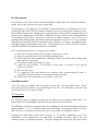
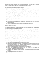
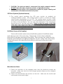
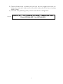
CPA
MAINTENANCE INSTRUCTIONS
NOTE – Failure to follow recommended maintenance procedures could void unit
warranties.
Interior Sanitization:
The interior of the unit should be cleaned and sanitized periodically. The frequency of
cleaning will be dependent upon the application and the HACCP procedures outlined
for the air-handling unit. It is extremely critical that the chemicals used to clean the unit
are compatible with the interior materials and components. It is recommended the
supplier of cleaners and sanitizers for the plant be consulted so they can make
recommendations on proper cleaning procedures and processes for the unit.
When cleaning the unit:
1. Make sure the unit is locked and tagged out per plant procedures.
2. Cleaning personnel should make sure to have proper protective clothing, as per
their standard operating procedures.
3. Make sure all of the filters have been removed from the unit.
4. Protect any control devices inside the unit with waterproof covering.
5. If the unit is supplied with UVC lights, protect both the light and the fixture from
the cleaning process.
6. Make sure that all of the drain connections are open.
7. Do not aggressively spray/wash the motor bearings. Aggressive washing can
damage the seal and wash out the grease. This can cause premature failure of
the bearing.
8. The coils can be cleaned however do not spray with high pressure system,
especially at an angle toward the fins. This can bend the leading edge of the
fins over. If the coil has aluminum fins do not use caustic cleaners.
9. Do not aggressively spray the gasketing on the filters. This can damage the
gasketing.
10. Do not aggressively spray the caulked seams in the unit. This can damage or
dislodge the sealing caulk.
Prior to putting the unit back in operation:
1. Make sure the interior of unit is as dry as possible. Operating before the unit is dry
can cause water to be airborne and damage the electrical components or get
the filters wet and damage them.
2. Make sure any drain caps that have been removed for cleaning, are replaced
and sealed.
3. Remove all protective coverings used during the cleaning process.
4. Check all the caulked seams in the unit for integrity. Caulking is a routine
maintenance item.
5. Check the gasketing on the filter frames. Replace if necessary.
6. Replace all filters and remove all protective material from interior components.
1
Pre-filter Service:
The prefilters in the CPA unit are a pleated synthetic media filter with a moisture resistant
frame, each held in place with two holding clips.
The frequency of changing of the prefilters is determined by the cleanliness of the air
passing through them and the proper operation of the unit during the cleanup cycle.
Most prefilter systems are changed on a preventative maintenance schedule and not
purely by the appearance of the filter. Visible dirt on the surface is not a true indication
of full loading of the filter. However, it can be an initial indicator. If the CPA unit is
supplied with a filter gauge, the filters should be changed at a 0.8” to 1.0” w.g. reading.
Typical life of the filter should be anywhere from 30 days to 90 days, depending upon
the application and operation of the unit. The prefilters are in stock at EVAPCO, please
call 507-446-8005 for immediate shipment of prefilters.
Use the following procedure to change the prefilters.
1) Stop the fan motor and lockout using the disconnect switch.
2) Remove each filter from their individual holding frame.
3) Inspect the filter frame gasketing, caulking between the frames and holding clips
and replace if necessary.
4) Clean and sanitize the prefilter section.
5) Install the new prefilters. The prefilters should have the pleats in the vertical
position if possible.
6) Start the fan motor.
7) It is suggested that the prefilters be checked after approximately 8 hours of
operation to ensure that they have been installed properly.
8) Make note in the maintenance schedule for the unit.
Final Filter Service:
CPA units can be supplied with two types of final filters, 95% and HEPA filters. These
filters are typically located at the discharge of the unit. The following is the servicing
procedures for the two types of filters.
95% Final Filters
The 95% filters are a cartridge type filter each held with four spring holding clips. The
filter media is a fine fiberglass material (with an optional synthetic filter).
The 95% filters should be changed when the reading on the final filter gauge indicates
approximately 1.1” to 1.2” pressure drop across the filters. The pressure drops should be
read with the unit operating, all service doors closed and new prefilters in place.
Typically the final filters should last 6 months to 15 months, depending upon the
cleanliness of the application, the frequency of prefilter changes, and if the unit
cleanup cycle is operated properly. The filter gauge will ensure the final filters have
2
reached their full life, and are not changed prematurely. The filters are in stock at
EVAPCO, please call 507-446-8005 for immediate shipment of filters.
Use the following procedure to change the filters.
1) Stop the fan motor and lockout using disconnect switch.
2) Remove the fully loaded final filters. (NOTE: Maintenance personnel may want to
use protective clothing and facemasks while changing.) Be careful not to
dislodge any of the particles collected in the filter.
3) Inspect the final filter frame gasketing (in some applications the gasketing is on
the filter and not the frame) and the retaining clips.
4) Check the caulking seal between the final filter frames. If any cracks are
observed, caulk with a USDA/FDA approved sealant.
5) Install the new 95% final filters. The pleats should be in the vertical position if
possible.
6) Clean and sanitize the final filter section.
7) Start the fan motor.
8) Make note in the maintenance schedule for the unit that the final filters have
been changed.
9) Check filter gauge for proper operation. Recalibrate if necessary.
Absolute (HEPA) Final Filters
The absolute (HEPA) filters are a cartridge type filter each held with four holding clips.
The filter media is a fine fiber glass material.
The absolute (HEPA) filters should be changed when the reading on the final filter
gauge indicates approximately 2.0” pressure drop across the filters. The pressure drops
should be read with the unit operating, all service doors closed and the prefilters in their
clean position.
Typically the final filters should last 6 months to 15 months, depending upon the
cleanliness of the application, the frequency of prefilter changes, and if the unit
cleanup cycle is operated properly. The filter gauge will ensure the final filters have
reached their full life, and are not changed prematurely. The filters are in stock at
EVAPCO, please call 507-446-8005 for immediate shipment of filters.
Use the following procedure to change the filters.
1) Stop the fan motor and lockout using disconnect switch.
2) Remove the fully loaded final filters. (NOTE: Maintenance personnel may want to
use protective clothing and facemasks while changing.) Be careful not to
dislodge any of the particles collected in the filter.
3) Inspect the final filter frame gasketing and the retaining clips.
4) Check the caulking seal between the final filter frames. If any cracks are
observed, caulk with a USDA/FDA sealant.
5) Install the new absolute (HEPA) final filters. The pleats should be in the vertical
position.
6) Clean and sanitize the final filter section.
7) Start the fan motor.
3
8) Make note in the maintenance schedule for the unit that the final filters have
been changed.
9) Check filter gauge for proper operation. Recalibrate if necessary.
Blower, Motor and Drive Assembly:
1) Every 6 months the fastening bolts for the blower, motor and drive should be
checked for tightness. Also, check the bearing set screws and the blower hub
set screws. Check alignment of the sheaves.
2) A periodic maintenance schedule should be set up for checking the belts. At
minimum, the belts should be checked every 6 to 9 months for wear and proper
tightness and alignment.
3) The blower bearings should be lubricated per the lubrication instructions and
schedule in the service manual.
4) Motors that do not have re-grease capability are factory lubricated for the
normal life of the bearings. For motors with re-grease capability, they should be
lubricated at these intervals:
Motor
Horsepower
3600
2
10
40
50 and above
Rated Speed (RPM)
1800
1200
5500
3600
2200
2200
12000
9500
7400
3500
18000
15000
12000
7400
900
22000
18000
15000
10500
Baldor motors should normally be greased with Exxon Mobil Polyrex EM grease
and U.S. motors either a Chevron SRI#2 or a Shell Dolium R.
Greasing procedure:
Clean the grease fitting (or the area around the hole, if equipped with slotted
grease screws. If motor has a purge plug, remove it. Apply grease gun fitting.
Too much grease or injecting grease too quickly can cause premature bearing
failure. Slowly apply the recommended amount of grease, taking 1 minute or
more to apply. Operate motor for 20 minutes, the reinstall purge plug if
previously removed. Caution: Mixing dissimilar grease is not recommended.
Amount of Grease to Add
Motor Horsepower
2
10
40
50 and above
Amount of Grease to
Add
Weight in Volume in
Ounces
Teaspoons
0.3
2.0
0.61
3.9
0.81
5.2
2.12
13.4
4
5) If the unit is supplied with spring isolation, check spring bolts/nuts for tightness.
Also, check the flexible duct for wear.
Electrical Connections:
The control system for the unit should be checked at least twice a year for proper
operation of the system. Also check all terminals to ensure they are tight. It is
suggested that the units be checked in the fall, prior to the heating season and in the
spring, prior to the summer cooling season. Make sure that all settings are per the
operation manual.
Smoke Detector (Optional Feature)
IMPORTANT: The smoke detector must be tested and maintained regularly following
NFPA 72 requirements. The detector should be cleaned and tested at least once a
year. Detailed information on maintenance and service is contained within the service
manual for this unit.
WARNING: WITHOUT PROPER SERVICE AND MAINTENANCE, THE SMOKE DETECTOR COULD
INITIATE FALSE ALARMS OR FAIL TO FUNCTION PROPERLY IN THE CASE OF A FIRE. STRICT
SERVICE AND MAINTENANCE SCHEDULES MUST BE FOLLOWED AND COMPLETE SERVICE
RECORDS KEPT.
Surge Drum Pressure Relief Valves (Optional Feature)
These tamper-resistant pressure relief valves are accurately factory set and do not
require any field adjustments whatsoever. They are intended for one time over-pressure
operation and should be replaced immediately after discharging because setting or
seat tightness may be altered. Every six months, relief valves shall be visually inspected
for corrosion or accumulation of scale and for leaks. Normally pressure-relief valves
should be removed and replaced with new valves at least every five years. Even when
simply replacing an existing valve, a review of requirements per current local and
national code is advisable. Valves should not be removed unless system has been
evacuated to zero pressure.
NOTE: See service manual for more detailed information.
Ammonia Detector (Optional Feature)
For proper operation it is essential that the test and calibration schedule be adhered to.
The supplier recommends the following maintenance schedule.
1) Response test once per month. Expose sensor to ammonia/water solution to
verify proper sensor response and alarm functions. Test more frequently in highly
critical applications.
2) Calibration should be performed with certified calibration gas every six months.
All tests and calibrations must be logged.
5
Sensor Life: These electrochemical cells are extremely reliable, but several things can
cause the cell chemicals to become depleted including:
1) A period of time.
2) Exposure to high temperatures.
3) Exposure to varying concentrations of the target gas.
4) Exposure to high moisture for extended periods without proper sensor enclosure
When the cell becomes depleted, the unit will give no indication of failure other than
that the sensor will not respond. For this reason it is absolutely essential that these units
be exercised with a gas sample on a regular and timely basis.
Typical sensor life in a refrigerated area will be 18 months to 2 years or more. Typical life
in a non-refrigerated area will be 12 months or less. Exposure to high levels of ammonia
will shorten these times. In addition to timely response checks, a preventative
maintenance program of periodic cell replacement should be implemented.
When the cell becomes depleted, a replacement cell can be obtained from Manning
Systems. Simply unplug the ribbon cable from the pins labeled Sensor, pull the old cell
from the spring clip, discard the old cell and replace it with a new one.
The sensor should be calibrated after a 24 hour warm-up period.
WARNING: WITHOUT PROPER SERVICE AND MAINTENANCE, THE AMMONIA DETECTOR
COULD INITIATE FALSE ALARMS OR FAIL TO FUNCTION PROPERLY IN THE CASE OF AN
AMMONIA LEAK. STRICT SERVICE AND MAINTENANCE SCHEDULES MUST BE FOLLOWED
AND COMPLETE SERVICE RECORDS KEPT.
ESS UVC Lights (Optional feature)
1) CAUTION! NEVER EXPOSE EYES OR SKIN TO UVC LIGHT. ALWAYS TURN
POWER OFF, OR WEAR GLOVES, FACE SHIELDS AND COVER ANY EXPOSED SKIN,
BEFORE SERVICING THE UNIT.
2) CAUTION! IMPROPER SERVICE AND MAINTENANCE CAN CAUSE FIRE, ELECTRICAL
SHOCK OR OTHER CONDITIONS THAT MAY CAUSE PERSONAL INJURY OR PROPERTY
DAMAGE.
3) The bulbs should be replaced every 12 – 18 months and should need no
maintenance between replacements. Carefully remove the old bulb(s) and
check all wiring and connections to the bulbs. Carefully inspect the watertight
assembly and replace if necessary.
4) Test all circuits. Leave the unit, close the access door, and then turn the
lights on. A “blue hue” will glow from the light indicating the fixture is
working. Remember – only view the lights through the service door
window, or while wearing the protective gear as described above.
5) Mark your preventative maintenance calendar to replace the bulbs one
year from the replacement date.
6) Check local codes for proper disposal of the used bulbs.
Desiccant Dehumidification (Optional feature)
6
1) CAUTION! The desiccant wheel is constructed of a fragile composite material.
DO NOT clean with water, chemicals, solvents, or high pressure sprays.
2) See the separate section in the maintenance manual for proper cleaning and
maintenance of the desiccant wheel and system.
VFD Drive Systems (Optional feature)
1) The control panel enclosing the VFD may contain an ambient air
cooling/ventilation system. This cooling system is used to control the interior
control panel temperatures for the VFD. The cooling system contains a filter
which must be periodically cleaned. It is recommended it be cleaned as least
as often as the pre-filters in the unit and more frequently if the atmosphere
around the unit is very dirty and dusty. Failure to keep the panel cooling filter
clean can cause reduced cooling air flow to the control panel. This can result in
overheating of the VFD which can then cause faults and or failure of the drive
and possible damage to the unit motor.
Unit Motor Removal Rail (option):
Some units include motor removal rail/trolley system to facilitate easier
and safer removal of the unit motor. Please refer to the trolley installation
instructions for proper mounting of the trolley. Prior to every use, make sure the
fasteners and hardware are tight and aligned. Do not “swing” the motor when
on the trolley since this may stress the beam or trolley and cause an unsafe
condition.
Miscellaneous Items:
1) Check the operation of the dampers every time the electrical controls are
checked. Make sure that all of the linkage operates freely and the dampers
function correctly.
2) Check the seal between the sections on the units. Make sure the section split
seals remain water and air tight.
7
3) Check all drain traps to make sure that they are not plugged and have an
adequate water seal. Make sure that the other drain pans do not have standing
water in them.
4) Check all door gasketing yearly to make sure there is an airtight seal.
2/1/1211
EVAPCO, Inc.
215 1st Street NE, P.O. Box 88
Medford, MN 55049
Phone: (507) 446-8005 Fax: (507) 446-8239
8