1
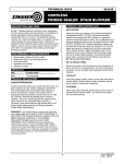
INSTALLATION
GUIDE,
OPERATION
AND SERVICE
MANUAL
NATURAL GAS
FIRED STORAGE
WATER HEATERS
Models RFF190
RFF280
‘B’ Series
T H I S
M A N U A L
M U S T
B E
K E P T
W I T H
T H E
A P P L I A N C E
June 2004
Part No. E515
the nation’s favourite for
PLUMBING & HEATING SUPPLIES
FREE SHIPPING
SECURE PAYMENTS
on all orders over £100 to mainland UK
shop online with confidence
FINANCE AVAILABLE
PRICE MATCH
spread the cost with low interest rates
always get the best deals available
we have
H U G E
R E D U C T I O N S
ON THOUSANDS OF ITEMS
Boilers
Bathroom suites
Radiators
Kitchen sinks & taps
Heating controls
Showers
Pipes & ittings
Wet rooms
Cylinders
Towel warmers
Fires
Bathroom furniture
Renewable energy
& much more
visit our website
plumbnation.co.uk
CALL US ON
0844
800
3460
© Copyright Andrews Water Heaters 2004
Reproduction of any information in this publication by any method is not permitted
unless prior written approval has been obtained from Andrews Water Heaters.
Andrews Storage Water Heaters have been designed and manufactured to comply
with current International standards of safety. In the interests of the health and
safety of personnel and the continued safe, reliable operation of the equipment,
safe working practices must be employed at all times. The attention of U.K. users is
drawn to their responsibilities under the Health and Safety Regulations 1993.
All installation and service on the Andrews Water Heater must be carried out by
properly qualified personnel, and therefore no liability can be accepted for any
damage or malfunction caused as a result of intervention by unauthorised
personnel.
The Andrews Water Heaters policy is one of continuous product improvement, and
therefore the information in this manual, whilst completely up to date at the time of
publication, may be subject to revision without prior notice.
Further information and assistance can be obtained from:
Andrews Water Heaters
Wednesbury One, Black Country New Road
Wednesbury, West Midlands WS10 7NZ
Tel: +44 (0)121 506 7400 Fax: +44 (0)121 506 7401
Email: [email protected]
Website: www.andrewswaterheaters.co.uk
THE ANDREWS WATER HEATERS COVERED IN THIS MANUAL
ARE FOR USE WITH NATURAL GAS ONLY
CONTENTS
SECTION 1
SECTION 2
PAGE
GENERAL AND SAFETY INFORMATION
General Information
2
British Standards
2
Health and Safety Regulations 1993
3
Legionellae in Water Heaters
3
TECHNICAL DATA
Appliance Dimensions
SECTION 3
SECTION 4
SECTION 5
INSTALLATION
Location
6
Flue Systems
6
Air Supply
7
Water Quality and Treatment
9
Water Connections
10
Vented Systems
10
Unvented Systems
11
Gas Connection
14
Electrical Supply
14
COMMISSIONING
To light the Burner
16
To Shut Off the the Burner
Users Safety Guide
16
17
OPERATION
To Check Main Burner Pressure
SECTION 6
4
18
SERVICING
Burner Assembly
19
Gas Control Valve
20
Flue Ways
20
Magnesium Anode(s)
21
Descaling Information
21
SECTION 7
FAULT FINDING
22
SECTION 8
PARTS LISTS AND ILLUSTRATIONS
24
SECTION 1
GENERAL
INFORMATION
GENERAL AND SAFETY INFORMATION
The Andrews Water Heater has been designed for use with NATURAL GAS only and is
manufactured to give an efficient, reliable and long service life.
To ensure the continued, trouble-free operation of your heater at maximum efficiency, it
is essential that correct installation, commissioning, operation and service procedures are
carried out strictly in accordance with the instructions given in this manual. By law,
installation and commissioning of the heater must be carried out by properly qualified
personnel.
The
The
The
The
heater(s) must be installed in accordance with the following requirements;
current GAS SAFETY (INSTALLATION AND USE) REGULATIONS
current BUILDING REGULATIONS
Water Supply (WATER FITTINGS) REGULATIONS 1999
Additionally, installation should be performed in accordance with all relevant
requirements of the Gas Supplier, Local Authority and recommendations of the British
Standards and Codes of Practice detailed below.
BRITISH
STANDARDS
AND CODES OF
PRACTICE
BS 6700: 1997
Specification for design, installation, testing and maintenance of
services supplying water for domestic use within buildings and their
curtilages. This standard supersedes the following British Standards
and Codes of Practice: CP99, CP310, CP324, 202, CP342 Part 2,
Centralised Hot Water Supply.
BS 5440
Part 1:2000
Part 2:1989
Installation of flues and ventilation for gas appliances of rated output
not exceeding 60kW.
Specification for installation of flues.
Specification for installation of ventilation for gas appliances.
BS 5546:1990
Installation of gas hot water supplies for domestic purposes.
BS 6891
Installation of low pressure gas pipework of up to 28mm in domestic
premises.
BS 7206:1990
Specification for unvented hot water storage units and packages.
I/M2
I/M5
Purging procedures for non-domestic gas installations.
Soundness testing procedures for industrial and commercial gas
installations.
Flues for commercial and industrial gas fired boilers and air heaters.
Notes on installation of gas pipework
(excluding 25mm and below).
I/M11
I/M16
NOTE:
2
Consideration should be given to amendments or updates to the
above standards.
GENERAL AND SAFETY INFORMATION
It is the duty of manufacturers and suppliers of products for use at work to ensure, so far
as is practicable, that such products are safe and without risk to health when properly
used and to make available to users, adequate information about their safe and proper
operation.
Andrews Water Heaters should only be used in the manner and purpose for which they
were intended and in accordance with the instructions in this manual. Although the
heaters have been manufactured with paramount consideration to safety, certain basic
precautions specified in this manual must be taken by the user.
SECTION 1
HEALTH AND
SAFETY
REGULATIONS
1993
It is imperative that all users of the heater must be provided with all the information and
instruction necessary to ensure correct and safe operation.
Water systems in buildings have been associated with outbreaks of Legionnaires' Disease,
particularly in health care facilities where occupants are significantly more susceptible to
infection.
In recognition of the risks in hospitals, a Code of Practice for the Control of Legionellae
in Health Care premises has been issued by the Department of Health (1991). Codes of
Practice applicable to other premises have been published by other organisations,
principally the Health and Safety Executive (HS)(G70) and the Chartered Institute of
Building Services Engineers (C1BSE, TM13).
EFFECTIVENESS
IN COMBATING
LEGIONELLAE
All Codes of Practice draw attention to the design and operation of water systems with
reference to avoidance of factors that favour colonisation by Legionellae bacteria. These
factors include stagnation, lukewarm conditions (20ºC to 45ºC) and the accumulation of
debris, scale and corrosion in the base of tanks and calorifiers.
Andrews Water Heaters has commissioned an independent evaluation of their products
to investigate their resistance to build-up of legionellae bacteria.
Experiments were conducted to determine whether, following a substantial challenge by
legionellae pneumophilia, after overnight and stagnation conditions, the system was
rendered free from viable recoverable legionellae. It was found that at 61ºC, following a
challenge of approximately 107 organisms per litre, within one hour, more than 99.999%
of organisms had been killed. After a subsequent stagnation period, sampling did not
reveal any residual contamination. The design of the base of the water heater precludes
legionellae colonisation, even after build-up of debris. The burner positioning ensures
that the water at the bottom of the heater reaches the same, or higher temperature as in
the rest of the heater.
Based on data obtained through experiment, the Andrews Water Heater can be described
as legionellae resistant as it is considered unlikely that, at the temperature tested, the
organism would colonise the water heater and present a possible health risk.
3
SECTION 2
TECHNICAL DATA
RECOMMENDED SERVICE CLEARANCE
J
H
E
F
B
K
D
RECOMMENDED SERVICE CLEARANCE
M
L
L
N
O
RECOMMENDED SERVICE CLEARANCE
RECOMMENDED SERVICE CLEARANCE
L
C
A
G
Fig 1.
MINIMUM SERVICE CLEARANCE
APPLIANCE
DIMENSIONS
4
MODEL
RFF190
RFF280
A
mm
inches
1448
57
1524
60
B
mm
inches
158
61⁄4
158
61⁄4
C
mm
inches
559
22
660
26
D
mm
inches
279
11
279
11
E
mm
inches
80
3
80
3
F
mm
inches
1397
55
1397
55
G
mm
inches
432
17
490
191⁄4
H
mm Min - Max
inches Min - Max
150 -300
6 - 12
150 - 300
6 - 12
J
mm Min - Max
inches Min - Max
483 - 7000
19 - 276
533 - 4000
21 - 156
K
mm
inches
310
121⁄4
310
121⁄4
L
mm
inches
305
12
305
12
M
mm
inches
345
131⁄2
396
151⁄2
N
mm
inches
275
11
326
13
O
mm
inches
610
24
610
24
TECHNICAL DATA
SECTION 2
ANDREWS MODEL NO.
RFF190
RFF280
Storage Capacity
litre
gallons
190
42
280
62
Recovery thro' 44ºC/80ºF
l/h
gal/h
291
64
339
75
Recovery thro' 56ºC/100ºF
l/h
gal/h
232
51
272
60
Heat Input
kW (Hs)
Btu/hr
19.5
66,534
23
78,476
Gas Flow Rate
m3/hr
ft3 /hr
1.82
64.3
2.15
76
Flue Gas Temp. (Approx)
ºC
ºF
70
158
70
158
Flue Gas Volume
m3/hr
32
29
Inlet & Flow Connections
R
R
(in BSPT/Ext)
3/4
3/4
3/4
3/4
Return Connection
R (in BSP/Int)
Rp (in BSP P/Int)
3/4
3/4
3/4
3/4
Weight Empty
kg
lb
75
165
132
292
Weight Full
kg
lb
273
603
418
908
Max Working Pressure
bar
psi
10
150
10
150
Max Test Pressure
bar
psi
20.6
300
20.6
300
Gas Family
12H (Natural)
Gas Connection
Rp
BSPT
1/2
1/2
1/2
1/2
Burner Pressure
mbar
wg
10.0
4.0
10.0
4.0
Injector Diameter
mm
No
3.90
24
4.20
19
Shipping Weight
kg
lb
84
185
144
317
Shipping Dimension Carton
HxWxD
mm
in
1785 x 600 x 660
70 x 24 x 26
1840 x 680 x 755
72 x 27 x 30
Mains Voltage
Frequency
220/240 - IP20
50Hz
Power Consumption
236W
Fuse
5 amp
5
SECTION 3
INTRODUCTION
INSTALLATION
THE LAW REQUIRES THAT INSTALLATION IS CARRIED OUT BY A PROPERLY
QUALIFIED PERSON
Install in accordance with current British Standard Code of Practice 342 part 2 and British
Standards 5440, 5546, 6644, 6700, 6798 and 6891.
LOCATION
The location chosen for the heater must permit the provision of a satisfactory flue and an
adequate air supply.
The heater must not be installed in a room which contains a bath or a shower and must
not be installed in a bedroom or bedsitting room.
A clearance of 3OOmm (l2in) should be left around the heater for fitting and servicing
purposes and 762mm (3Oin) above the heater for removal of the flue baffle. The above
clearances are recommended for ease of servicing. They can be reduced if necessary but
a clearance of 3OOmm (12in) must be left in front of heater for access to the burner and
controls. The flue baffle clearance should also be maintained if possible to avoid servicing
problems.
The floor on which the heater is installed must be flat, level and of sufficient strength to
withstand the weight of the heater when filled with water, and should satisfy the
requirements of the Local Authority & Building Regulations.
Any combustible material adjacent to the heater must be so placed or shielded as to
ensure that its temperature does not exceed 65ºC (150ºF).
FLUE SYSTEM
Detailed recommendations for flueing are given in British Gas booklet IM/11 and BS
5440 part 1. The following notes are intended to give general guidance:
• Route. The route of the flue is not critical but, when planning horizontal runs,
potential condensate traps must be avoided.
When calculating maximum flue runs, a reduction must be made of 1 metre run per
90° elbow and a 1/2 metre run per 45° elbow.
• Location. The siting of the flue terminal is not critical with respect to the performance
of the unit. However, areas where the discharge of combustion products would cause
a nuisance should be avoided.
In accessible positions a suitable guard should be provided.
RFF190 &
RFF280 FLUE
FITTING
INSTRUCTIONS
1. Fit spigot adaptor E4 to heater flue spigot in the direction shown. Note! Fire resistant
silicon sealant should be used on this joint.
2. Fit elbow E3 into spigot adaptor E4 for horizontal flue routes or E2 for vertical flue
routes.
3. Fit flue pipe into E2 to give required length of flue route. Refer to manual for
maximum horizontal and vertical flue routes.
4. Determine correct position and fit outer wall plate using 4 screws and rawplugs
provided. Cut flue sleeve to suit wall thickness and fit flue pipe through wall to outer
wall plate. Fit inner wall plate and fix using 4 screws and rawplugs provided.
5. The lengths of flue pipe may be cut to obtain correct length of flue route required.
6. On vertical flue installations it is important to fit the correct flue terminal E4 supplied
by Andrews Water Heaters.
7. For further information contact Andrews Technical Dept.
E5
E3
E2
E4
6
E2
E2
E2
E1
Components
supplied
in Flue Kit
INSTALLATION
SECTION 3
(a Max)
FLUE SYSTEM
Size
RFF190
RFF280
a
8m
5m
b
7m
4m
(b Max)
0.3m
Fig 2.
Typical Flue
Installation
Detailed recommendations for air supply are given in BS 5440 part 2.
AIR SUPPLY
The following notes are intended to give general guidance:
Where the heater is to be installed in a room or internal space the heater requires the
room or internal space containing it to have a permanent air vent. The vent must be
either direct to outside air or to an adjacent room or internal space which must itself have
a permanent vent of at least the same size direct to outside air. The minimum effective
area of the permanent air vent(s) required is as follows:
5 cm2 per kW in excess of 7 kW
Where the heater is to be installed in a compartment, permanent air vents are required in
the compartment at high and low level. These air vents must either communicate with a
room or internal space or be direct to outside air.
The minimum effective areas of the permanent air vents required in the compartment are
as follows:-
Air Vent Areas
Position of
Air Vents
Air from room or
internal space
Air direct from
outside
High Level
10 cm2 per kW
5cm2 per kW
Low level
20cm2 per kW
10cm2 per kW
7
SECTION 3
AIR SUPPLY
INSTALLATION
Note: - Both air vents must communicate with the same room or internal space or must
both be on the same wall to outside air.
Where compartment air vents are open to a room or internal space, the room or internal
space must itself have a permanent air vent(s) as previously specified.
For multiple installations where the total heat input exceeds 60 kW (204,720 Btu’s/hr),
reference must be made to BS 6644. The table on p7 should be used to calculate
requirements. Detailed recommendations are given in BS 6644 Clause 19.
The following notes are intended to give general guidance.
Ventilation shall prevent the heater environment from exceeding 32°C (90°F).
The purpose provided space housing the heater(s) must have permanent air vents
communicating directly with the outside air, at high and low level. Where communication
with the outside air is possible only by means of high level air vents, ducting down to
floor level for the lower vents should be used.
For an exposed building, air vents should be fitted preferable on all four sides, but on at
least two sides.
Air vents should have negligible resistance and must not be sited in any position where
they are likely to be easily blocked or flooded or in any position adjacent to an extraction
system which is carrying flammable vapour or other contaminated air.
IMPORTANT
The supply of air to a space housing the heater(s) by mechanical means should be:(a) Mechanical inlet with natural extraction.
(b) Mechanical inlet with mechanical extraction.
NB - Natural inlet with mechanical extraction must not be used.
Where a mechanical inlet and mechanical extraction system is used, the design
extraction rate must not exceed one third of the design inlet rate.
All mechanical ventilation systems must be fitted with automatic gas shut off safety
systems which cut off the supply of gas to the heater(s) in the event of failure of
either the inlet or extract fans.
NB - The vapours given off by halogen based compounds can, if drawn
into the combustion air, cause corrosion of the Storage Vessel and
premature failure of the thermocouple.
If water heaters are to be installed in locations where halogens are likely to be
present they should be isolated from such compounds and ventilated from and to
outside, uncontaminated, atmosphere.
Some of the vulnerable areas are listed below:(i) Hairdressing salons and adjoining rooms and basements.
(ii) Establishments where dry cleaning solutions are used or stored.
(iii) De-greasing plants using hydrocarbon solvents.
(iv) Premises where refrigerant gases are used or stored.
(v) Environments with dust laden atmosphere
8
INSTALLATION
SECTION 3
WATER QUALITY AND TREATMENT
Where extreme conditions of water hardness exist, scale can form in any water heating
equipment, especially when the heater is working under conditions of constant heavy
demand and at high temperatures.
WATER
CONNECTIONS GENERAL
Each water heater is fitted with one or more magnesium anode(s) which protect the tank
from corrosion caused by electrolytic action. Magnesium anodes are sacrificial in that
they corrode as they protect. When the anode has eroded to less than 50% of it's
original diameter, it may not offer protection.The anodes should be inspected annually
and replaced as necessary. Frequency of anode replacement will vary dependent on water
quality.
Andrews Water Heaters offer CorrexTM UP powered anodes as an alternative to the
standard magnesium anodes. These anodes do not need maintenance or replacement.
The potentiostat which regulates the current to the CorrexTM anode, features an indicator
light which shows green to indicate correct function and red to indicate malfunction.
These anodes are available as an optional extra on all Andrews heaters.
In hard water areas, scale formation can occur in hot water systems and hot water
heaters and the higher the temperature and volume of water used, the more problematic
the scale build-up can be. Water treatment is normally recommended when the hardness
reaches 100 - 150ppm (7 - 10 degrees Clark) and above. This problem can be minimised
by reducing the water temperature in the heater and by fitting suitable water pretreatment equipment.
When installing Andrews Water Heaters in hard water areas we would recommend
that a water treatment specialist is consulted.
HYDROJET
SYSTEM
How the system works
The upper “jet ports”
direct the flow outward
to begin the dynamic
mixing action.
The lower “jet ports”
direct the flow
inward to increase
the turbulence.
The heater is fitted with the Hydrojet Total Performance System incorporated in the cold
inlet dip tube. The tube is designed to increase turbulence and reduce sediment build up,
reduce thermal stacking and increase delivery.
9
SECTION 3
WATER
CONNECTIONS VENTED
SYSTEMS
INSTALLATION
The water heater must be supplied from a cold water feed cistern and the hot water
supply pipe must be fitted with an open vent pipe in accordance with BS 5546. Local
regulations and bye-laws must be observed when installing the system but typical water
service layouts are shown in Figs. 3 and 6.
The cold water feed cistern must have an actual capacity greater than the hourly
recovery rate of the heater or heaters to which it is fitted, the minimum actual capacity
allowed for a feed cistern is 227 litres (50 gall).
The actual cistern capacity is the capacity to the normal water line of the cistern. All
cisterns used should be to the relevant British Standard and the distance from the normal
water line to the top of the cistern should be as laid down by the water authorities.
The cold water inlet and hot water outlet are identified on top of the heater. Connect the
cold water feed and hot water outlet to these nipples with union adaptors for ease of
servicing. (See Servicing Section 6).
CAUTION - DO NOT APPLY HEAT TO THESE NIPPLES IF MAKING CAPILLARY
SOLDERED JOINTS AS THEY ARE FITTED WITH PLASTIC INSERTS. MAKE THE
CAPILLARY JOINTS TO THE PIPES BEFORE CONNECTING TO THE HEATER. A
DRAIN COCK IS SUPPLIED WITH THE HEATER AND THIS SHOULD BE FITTED
TO THE APPROPRIATE BOSS AS SHOWN ON THE DRAWING.
After installation of the water system open the main water supply valve, flush the system
and fill the heater. Open the hot taps to allow air to escape from the system. When the
system is free of air, close the taps and check for leaks at the gas control thermostat,
drain cock and pipe connections at the top of the heater.
Open Vent
Stop Valve
Cold Water Feed
Overflow
Cold Water Cistern
Hot Water
Service Pipe
Cold Water
Inlet Valve
Flue
Union
Adaptor
Gas Cock
Gas Control
Gas Supply Pipe
Thermostat
Drain Cock
Fig 3.
10
Check Valve
Secondary return via
Tee in Drain Port
INSTALLATION
Unvented Systems should be fitted by an Approved Installer.
When used in an unvented system, the Andrews Water Heater will supply hot water at
a pressure of 3.5bar (50.8lbf/in2) provided that this pressure is available at the mains
feed. During conditions of no-flow, system pressure may rise to a maximum of 6bar
(87lbf/in2) whilst the burner is operating. When testing the system, it is recommended
that a maximum test pressure of 8.62bar (125lbf/in2) is employed.
SECTION 3
WATER
CONNECTIONS UNVENTED
SYSTEMS
The heater can be used on unvented hot water storage systems, with the addition of
an Unvented Systems Kit, part number B171 available from Andrews Water Heaters.
All fittings and materials must be suitable for use with drinking water and listed in the
current Water Research Centre "Materials and Fittings Directory".
Installation of unvented hot storage water systems must comply with Part G of
Schedule 1 of the Current Building Regulations.
Fig.4 p12 lists and illustrates the component parts of the Unvented Systems Kit.
Fig.5 p13 illustrates the general arrangement of the components.
The Wall Mounting Kit is available as an optional extra.
Items D4/D6 must be fitted into the Temperature Relief port (see Fig.6, p13).
When assembling items D1 and D2 care must be taken to ensure that the flow arrows
marked on the components are pointing in the direction of flow i.e. towards the water
heater.
The cold water for services may be drawn from the 22mm compression port on item
D1(a). The water pressure at this point will be similar to that available at the hot water
outlet of the water heater. If port (a) is not used it should be sealed with the blanking
plug supplied.
If higher flow rates are required for the cold water services a suitable “tee” fitting
should be included in the pipework upstream of item D1.
The pipework fitted to both tundish outlets should be at least 28mm diameter and
should be terminated at a suitable drain (see Current Building Regulations Approved
Document G3).
11
SECTION 3
INSTALLATION
Unvented
Systems Kit
Fig 4.
Unvented
Systems Kit
Ref.
D1
D2
D3
D4
D5
D6
D7
D8
12
Part No.
Description
Qty
B171
C780
C781
C782
E462
C783
C772
B173
C788
C787
Unvented Systems Kit Complete
Pressure Reducing Valve/Strainer
Check Valve / Expansion Vessel
Expansion Vessel
Temperature/Pressure Relief Valve
Tundish
Adaptor
Wall Mounting Kit for Expansion Vessel
Hose Assembly
Wall Bracket Assembly
1
1
1
1
1
1
1
1
1
INSTALLATION
SECTION 3
Fig 5.
D3
D1
Hot Water Service Pipe
Cold Water Take Off
D6
D2
D4
D5
Check Valve
Secondary return via
Tee in Drain Port
Cold Water Inlet
Fig 6.
13
SECTION 3
GAS
CONNECTIONS
INSTALLATION
THE APPLIANCE MUST ONLY BE USED WITH NATURAL GAS.
The installation of the gas supply should conform to the requirements of IM/16 published
by British Gas p.l.c. or BS 6891. Jointing compound used must conform to BS 5292 pt 5.
CAUTION - DO NOT APPLY HEAT IN CLOSE PROXIMITY TO THE GAS CONTROL
AS THIS WILL RESULT IN DAMAGE OCCURRING TO THE CONTROL.
Fit the 1⁄2 m/f elbow into the gas control valve. Fit the 1⁄2 gas supply cock immediately
upstream of the gas control and elbow and connect to the gas supply. Pressure test the gas
installation for soundness. If any doubt exists as to size of gas supply pipe, consult your
local Gas Region.
It is recommended that a pressure test point is fitted on the input next to the gas supply
valve.
ELECTRICAL
SUPPLY
The method of connection to the mains electricity supply should facilitate complete
electrical isolation of the appliance preferably by use of an unswitched fused spur.
Alternatively, a fused double pole switch or fused spur box, serving only the heater, may be
used. A 3mm separation is required between each pole.
The point of connection to the mains should be readily accessible and adjacent to the
appliance.
Wiring external to the water heater must be installed in accordance with the I.E.E.
Regulations for the wiring of buildings and to any local regulations that may apply.
The Heater is designed to run off a permanent 220/240V 1 Ph 50 Hz supply and the fuse
rating is 5 Amp.
Important Note
If the electrical power supply cable needs to be replaced it must be purchased from
the heater manufacturer.
14
INSTALLATION
SECTION 3
Fig 7.
WARNING DO NOT SWITCH OFF HEATER ELECTRICAL SUPPLY UNLESS CARRYING OUT
MAINTENANCE
15
SECTION 4
COMMISSIONING
CAUTION: DO NOT OPERATE THE WATER HEATER UNTIL THE STORAGE VESSEL IS
COMPLETELY FILLED WITH WATER, WITH WATER RUNNING FROM ALL HOT TAPS.
Open the main gas supply valve after all connections to the gas control valve are
complete, and test all connections with soap solution.
Lighting the burner
RESET
Temperature
Dial
VERY
HOT
LOW
HOT
Thermostat Setting
Approx Water Temperature
LOW
108ºF
HOT
42ºC
130ºF
VERY HOT
54ºC
156ºF
69ºC
Fig 8.
1. Set thermostat temperature dial to the desired position. Remove the thermostat cover
on the right hand side of the gas control valve. The thermostat can now be adjusted
to the required temperature. (See above). Replace thermostat cover.
Note: Before adjusting thermostat ensure electrical supply is switched off.
2. Ensure gas supply is on.
3. Ensure electrical supply is on.
4. Ensure time switch, if fitted is in the on position.
5. If the burner does not light the red alarm lamp will illuminate on the gas control
panel. Wait a few seconds and press the reset button (See fig 9). The burner
should now light.
Shutting off burner
To shut off the burner isolate the electrical supply, then shut off the gas service cock.
The water heater should only be turned OFF for long periods, eg holidays, or in an
emergency. Otherwise the heater should be left to operate under normal thermostat
control.
NB. When using a time control ensure the heater is not turned OFF before the final
water draw off occurs. This will ensure the water in the tank is left in a hot condition.
16
COMMISSIONING
For your safety read before lighting the appliance
WARNING
1. Always follow manufacturers instructions when lighting the appliance.
Failure to do so may result in damage to property, personal injury or loss of life.
SECTION 4
USERS SAFETY
GUIDE
2. Before lighting check all round the appliance area for gas.
3. Do not make any attempt to re-light the appliance if the main burner has
extinguished. Wait at least 5 minutes to allow for any unburnt gas to disperse.
Ventilate the area if possible.
FOR YOUR SAFETY IF YOU SMELL GAS
1. Turn off gas supply and open windows.
2. Do not operate electrical switches.
3. Extinguish any naked flames.
4. Contact gas supplier if the smell of gas persists.
FOR YOUR SAFETY
Do not store or use petrol, aerosol or other flammable vapours or liquids in the
vicinity of this or any other atmospheric gas appliance.
WARNING
Hotter water increases the risk of scalding. Before changing the temperature refer
to instruction manual or data label. Hot water can produce third-degree burns in:
6 seconds at 140ºF (60°C)
30 seconds at 130°F (54°C)
17
SECTION 5
OPERATION
Checking main burner pressure
BURNER
ASSEMBLY
1.
2.
3.
4.
Turn gas supply OFF.
Release bleed screw A and connect pressure gauge tube (See Fig. 9)
Light burner as described previously.
Remove cap from port B and adjust pressure using exposed screw in accordance with
data plate (See Fig. 9)
5. Shut OFF burner as described previously. Remove pressure gauge tube and tighten
bleed screw A.
6. Re-light burner as described previously.
Alarm
A
Reset
Button
B
Fig 9.
When properly installed and adjusted the Heater will require the minimum of attention.
Should it become necessary to completely drain the heater, close the cold water inlet valve,
open a hot water tap to allow air to enter the system. Fit a suitable hose to the drain cock
and open.
Whenever the Heater is filled with cold water condensation will form on the cold storage
vessel surfaces when the burner is lit. Condensation is normal and does not indicate a leak.
It will disappear when the storage vessel becomes heated.
The control thermostat fitted to this heater has a built in limit thermostat (ECO). In the
event of high water temperature the gas supply will be shut off automatically. The high
temperature condition must be identified and rectified before the heater is relit. The
thermostat has a manual reset button which is pressed to close the ECO and allow the
heater to be relit.
IF IN DOUBT CONTACT ANDREWS WATER HEATERS
18
SERVICING
Whilst giving the following instructions for the care of the Andrews Water Heater, we
would recommend that an arrangement is made with your local gas region or installer to
carry out periodic checks of the appliance to ensure trouble free operation and continued
satisfaction.
SECTION 6
BURNER
ASSEMBLY
The burner assembly should be cleaned and checked annually as follows:1.
Move the gas service cock to "OFF". Isolate from the electrical supply. Unhook and
remove the outer door. Remove inner door by sliding it to the side on the RFF190
model, or by removing two screws on the RFF280 model.
2.
Disconnect from the bottom of the gas control valve, the pilot tube, thermocouple,
bleedline and main burner supply tube. Withdraw the burner assembly from the
heater complete with blue ignition lead, disconnect from gas control panel.
3.
Remove the screw securing the pilot assembly to the main burner supply tube.
4.
Remove the gland nut connecting the pilot tube to the pilot assembly. Withdraw the
pilot tube and remove the pilot restrictor from the end. Clean the pilot restrictor and
blow through the pilot burner with compressed air.
5.
Remove the main burner pipe jet assembly from the burner by rotating jet
anticlockwise, remove jet and clean. Blow through the main burner with
compressed air.
DO NOT ATTEMPT TO CLEAN ORIFICES WITH SHARP METALLIC OBJECTS,
IF NECESSARY, USE A WOOD SPLINTER TO CLEAR.
6.
Re-assemble in the reverse order of steps 2 to 5 but note:
i)
7.
Be sure to engage the rear pins of the main burner on the RFF280 model or the
flattened flange of the main burner supply tube on the RFF190 model into their
proper locations in the bracket on the base pan of the heater.
Re-light and carry out commissioning check as pages 16 and 17.
19
SECTION 6
SERVICING
This should be checked and serviced by an engineer fully conversant with every aspect of
this piece of equipment.
To change the gas valve it is not necessary to drain down the water heater. See below
Retaining screws
GAS CONTROL
VALVE
Gas control bracket
To remove gas control,
unscrew four retaining screws
at top and bottom of gas
control bracket. Also it will be
necessary to remove gas
fittings at the top of the gas
valve and the bottom of the
gas valve. It is now possible
to slide the gas control valve
away from the gas valve
retaining bracket.
Fig 10.
Retaining screws
1.
Move the gas control knob to "OFF". Isolate from the electrical supply. Unhook and
remove the outer door and remove the inner door by sliding to the side on the
RFF190 model, or by removing two screws on the RFF280 model.
2.
Disconnect burner gas tube, pilot tube and blue ignition lead at gas control.
3.
Remove burner assembly complete with pipes and blue ignition lead.
4.
Disconnect electrical connection from the top of the heater. Remove the screws that
hold the flue-fan in place and remove the flue fan.
5.
Withdraw the flue baffle.
6.
Clean the flueway with a brush and clean any deposit from the underside of the
storage vessel bottom and from the flue baffle.
7.
Re-assemble in the reverse order.
IT IS IMPORTANT THAT THE BURNER IS CORRECTLY LOCATED IN THE BURNER
SUPPORT BRACKET ON BASE OF COMBUSTION CHAMBER.
8.
20
Re-light and carry out commissioning check as pages 16 and 17.
SERVICING
A magnesium sacrificial anode is fitted in the water storage vessel. The function of the
anode is to provide additional protection, against corrosion, for the inside of the vessel.
The condition of the anode should be checked regularly and replaced. In order to remove
the anode close the cold water feed stop valve, open a hot water tap and, by opening
the water heater drain valve, drain off sufficient water to clear the top of the vessel. The
anode/outlet nipple can then be unscrewed from the top of the heater.
SECTION 6
MAGNESIUM
ANODE
The original diameter of the anode is 22mm (7⁄8”). If, at any point along its length, the
anode is eroded to half, or less, of the original diameter is should be replaced with new.
Particular attention should be paid to the extreme ends.
If the anode is encrusted with limescale it should be either cleaned or replaced.
Where Correx Anodes are fitted no Anode maintenance is required.
When descaling the storage water heater your attention is drawn to the following
guidelines.
SAFETY FIRST - DUE TO THE CORROSIVE NATURE OF THE DESCALE FLUID IT IS
ESSENTIAL THAT SUITABLE PROTECTIVE CLOTHING EQUIPMENT IS USED AND
ADEQUATE VENTILATION IS AVAILABLE WHEN DESCALING. IT IS IMPORTANT TO
FOLLOW DESCALING MANUFACTURES INSTRUCTIONS BEFORE AND DURING USE.
1.
Turn gas control on water heater to ‘OFF position and isolate the gas supply.
2.
Close water inlet valve and drain heater tank.
3.
Remove magnesium sacrificial anode.
DESCALING
INFORMATION
Note: It is recommended that a new anode is fitted.
4.
Add suitable hydrochloric based descale acid, the requirement is normally 5 litres for
dependent on the amount of limescale present.
5. After a minimum of one hour restore gas supply and turn on main gas burner for 2
minutes (MAXIMUM).
6. Isolate gas supply and drain off descale fluid through drain port.
7. Open cold water feed valve and fill heater tank.
8. Drain and flush out heater for minimum of 30 minutes.
9. Replace anode.
10. Restore gas supply and re-light heater.
21
SECTION 7
FAULT FINDING
FAULT
22
ACTION
NO IGNITION
AT PILOT
(a) Power to unit interrupted
(b) Thermostat faulty
(c) Spark ignition control module faulty
FLUE FAN RUNS
NO IGNITION
SPARK
(a) Faulty air pressure switch
(b) Faulty spark ignition lead
FLUE FAN DOES
NOT RUN
(a) Power to unit interrupted
(b) Faulty fan motor
(c) Flue fan ECO actuated
CONTINUOUS
IGNITION NO
PILOT FLAME
(a) Check gas service cock is open
HEATER WILL
NOT LIGHT
LOCKOUT
ALARM
ILLUMINATED
(a) Check gas service cock is open Press reset button
Check action of flue fan ECO. If this switch is
Actuating check:
MAIN BURNER
OUTAGE AT
PERIODIC
INTERVALS
(a) Sufficient ventilation is provided
(b) The resistance of the flue system is to high
(c) The burner pressure is to high
(d) The flue fan ECO is faulty
FAULT FINDING
FAULT
SECTION 7
ACTION
WATER
TEMPERATURE
TOO HIGH
(a) Reset thermostat to lower temperature.
(b) Thermostat faulty. Check and replace if necessary.
(c) Main gas valve not closing. Clean or replace.
WATER
TEMPERATURE
TOO LOW
(a) Reset thermostat to higher temperature.
(b) Check gas pressures at burner and at gas inlet to heater.
(c) Thermostat faulty. Check and replace if necessary.
NOT ENOUGH
HOT WATER
(a) Check gas pressures at burner and at gas inlet to heater.
(b) Check amount of water being used against recovery rate
given on data plate. If usage too high, more heating
capacity needed.
WATER DRIPPING
FROM BASE OF
HEATER
(a) Check if this stops when water in heater is hot. If yes, then
condensation is the problem caused by incorrectly designed
flue or by tank cooling excessively, i.e. more hot water
being used than recovery rate of heater. If so, more
heating capacity needed.
(b) If water continues to drip when heater is hot, problem is
leaking joint or storage vessel.
RUMBLING NOISE
(a) Scale formation in heater, consult water treatment
specialist. Heater must be descaled and suitable water
treatment provided to avoid re-occurrence.
23
SECTION 8
PARTS LIST RFF190 & RFF280
C1
C3
A2
A1
C2
B12
B7
B5
B10
B8
A9
A6
B4
B2
B11
B3
B6
B1
B9
A3
A5
A4
A7
A8
A7
A8
E5
E3
E2
E4
24
E2
E2
E2
E1
PARTS LIST RFF190 & RFF280
Model
Ref.
RFF190
SECTION 8
RFF280
Part Numbers
Description
Qty
A1
E163
E164
Hot Outlet Nipple/Anode
1
A2
E165
E166
Hydrojet Cold Inlet Diptube
1
A3
C247
C247
3/4NPT x 3/4 BSP Nipple
1
A4
C103
C103
Socket Coupler
1
A5
C381
C381
Drain Cock
1
A6
E533
E533
Flue Baffle
1
A7
E168
C660
Cover, Combustion Chamber
1
A8
E169
C329
Cover, Burner Access
1
A9
E501
E501
Thermostat Cover Access
1
B1
E502
E503
Burner Assembly
1
B2
E504
E504
Pilot Supply Pipe
1
B3
E174
E530
Burner Supply Pipe
1
B4
E353
E353
Burner Head
1
B5
E505
E505
Gas Control Valve
B6
E531
E532
Injector
1
B7
C382
C382
Gas Cock
1
B8
E506
E506
Spark Ignition Control
1
B9
E507
E507
Pilot Burner Jet N18
1
B10
E508
E508
Pilot Assembly
1
B11
E509
E509
Thermostat
1
B12
E561
E561
1/2” BSP M/F Elbow
1
C1
E510
E511
Flue Fan Assembly
1
C2
E512
E513
Air Pressure Switch
1
C3
E554
E554
Flue Fan ECO
1
Ref.
ANDREWS Part Numbers
B176
Description
Qty
Flue Terminal Assembly
1
Comprises
E1
C791
Wall Outlet Terminal (includes flue sleeve)
1
E2
E361
Flue 500mm x 80mm ø
4
E3
C792
Elbow 90º
1
E4
C790
Adaptor
1
Optional Extras
E5
C794
E045
C793
Elbow 45º (Not Shown)
Flue Terminal
Flue 1000mm x 80mm ø
NOTE:
Extra elbows and flue lengths can be ordered as required. Flue terminal is only used on vertical flue installations.
25
Notes
26
Wednesbury One,
Black Country New Road
Wednesbury,
West Midlands WS10 7NZ
Tel: +44 (0)121 506 7400
Fax: +44 (0)121 506 7401
Email: [email protected]
Website: www.andrewswaterheaters.co.uk
06/04