1
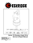
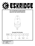
S78P AND 78P PLANETARY AUGER DRIVE WITH KICKDOWN
OPTION
Example Part Number
S7835
6P
5
F58
Model
Shaft Plate Retained
Bail
Motor
Code
THIS SERVICE MANUAL IS EFFECTIVE
FROM: ..... S/N 26435, NOVEMBER 1999
TO:........... CURRENT
REF: ........ SMS78PK2-BB
—
RK2
Options
S78 (WITH KICKDOWN OPTION) SERVICE MANUAL
SINGLE SPEED PLANETARY AUGER DRIVE
This manual will assist in disassembly and assembly of major components for all Model S78 Planetary Auger Drives. Item numbers,
indicated in parentheses throughout this manual, refer to the Eskridge Model S78 exploded parts breakdown drawings. Individual customer specifications (bail assembly, output shaft, hydraulic motor, etc.) may vary from exploded drawing and standard part numbers
shown; if applicable, refer to individual customer drawings for details.
LUBRICATION & MAINTENANCE
Change the oil after the first 50 hours of use and at 500 hour intervals thereafter. Gear drives in auger drives require GL-5 grade AP 80/90
gear oil for lubrication. The manufacturer recommends that the unit be partially disassembled to inspect gears, spines and bearings at
1000 hour intervals.
The oil capacity of this unit is 6.5 pints. Proper oil level will measure to middle of primary cluster gears when auger drive is in vertical
position.
!
WARNING: While working on this equipment, use safe lifting procedures,
wear adequate clothing and wear hearing, eye and respiratory protection.
CONTENTS
Example Part Number ........................................................................................................................................1
Lubrication & Maintenance................................................................................................................................2
Unit And Kickdown Kit Disassembly Procedure .............................................................................................3
Primary Planet Carrier Subassembly ...............................................................................................................4
Secondary Planet Carrier Subassembly ..........................................................................................................4
Bearing Carrier Subassembly ...........................................................................................................................5
Unit And Kickdown Kit Reassembly Procedure ..............................................................................................5
Exploded View Drawing .....................................................................................................................................7
2
so now. (Sometimes the sun gear remains in the primary
carrier (7).)
Unit Disassembly Procedure
(Refer to exploded view drawing on Page 6)
1)
2)
Scribe a diagonal line across the outside of the auger drive,
from the bail assembly (35) to the bearing carrier (4), to
assure proper orientation of parts as they are reassembled.
13)
Remove primary ring gear (6).
14)
Remove secondary ring gear (5) and o-ring (30).
15)
The output shaft (2) and secondary planet carrier assembly
may now be removed as follows:
To drain oil, position unit vertically and remove oil plug (28)
located in the bearing carrier (4). To help ventilate oil while
draining, loosen or remove oil plug (37) located in cover (1).
Maximum drainage occurs when oil is warm.
NOTE: Particular care should be taken when placing the unit
in a position for servicing. Unit should be blocked up so that
weight of the unit is resting on the bearing carrier (2). This
fixture must be secure so that the auger drive will not tip over
during disassembly and assembly procedures.
a)
The secondary planet carrier (8) spline is a press fit onto
output shaft (2) spline. Bearing carrier (4) should be set
on plate or table with output shaft protruding downward
through hole in table.
b)
Loosen, but do not remove, shaft retaining cap screws
(29).
NOTE: Care should be taken not to damage output shaft or
injure your feet when shaft falls out of case.
Note: Serial numbers through 38201 were manufactured with the
kickdown valve attached to a bracket on the bail. Those built
after this serial number range were built with the kickdown
valve attached to a bracket which is clamped to the motor.
c)
Press output shaft out bottom of case by applying press
load to top end of cap screws (29). Remove cap screws
to allow shaft to pass through case.
Note: If the kickdown valve was performing acceptably prior to taking the digger out of service, do not adjust the kickdown valve
setting.
16)
Lift the secondary planet assembly out of the unit (includes
Items 8, 11, 13, 15, 17, 18, 21 & 23). Use a puller, if needed.
3)
With either style, begin by removing the two pressure sense
lines (A) and (B) which run from the hydraulic motor (34) inlet
port and outlet port to the kickdown valve body (38).
17)
The unit is now disassembled into subassemblies. The
area(s) requiring repair should be identified by thorough
inspection of the parts after they have been cleaned and
dried.
4)
Remove the small fitting (K) from the large -16 fitting (40) on
the outlet port of the motor (34). Remove the large -16 fitting
(40).
5)
Remove the shift control tube (C) which runs from the kickdown valve body (38) to the shift port on the motor (34).
6)
7)
Adjustment screw
Locknut
If your digger falls within the serial number range stated
above, loosen the two cap-screws (41) which attach the kickdown valve body (38) to the bail bracket, otherwise, proceed
to the next step.
B
A
F
Remove the twelve hex-head cap screws (22) and hex-flange
nuts (24) from bail assembly (35). Lift bail assembly from
unit.
H
K
K
40
G
NOTE: There are no bolts retaining the major components
together; proceed with caution when moving the unit.
C
F
38
8)
9)
Remove the tube (E) which runs from the kick-down valve
body (38) to the drain port of the motor (34) and the tube assembly (D) which runs from the drain side of the shift spool
to the drain port of the motor (34). On units with the serial
numbers listed above, the kickdown valve is now free to be
removed. On those diggers made since the above serial
number range, loosen the T-bolt clamp (44) and slide the
bracket (43) and kickdown valve (38) off the motor (34).
E
Remove cover (1), input gear (9) and o-ring (30).
11)
Lift the primary planet carrier assembly out of the unit
(includes Items 7, 10, 12, 14, 19 & 23).
12)
If sun gear (16) has not been removed from auger drive, do
D
J
Remove the two cap screws (32) and lock washers (33) from
hydraulic motor (34). Remove motor from unit. Check o-ring
(31) for damage.
10)
H
L
3
I
34
12
Primary Planet
Carrier Subassembly
Secondary Planet
Carrier Subassembly
(Items 7, 10, 12, 14, 19 & 23)
(Items 8, 11, 13, 15, 17, 18, 21 & 23)
13
10
11
8
7
18
19
21
17
14
23
15
12
13
23
Disassembly
Disassembly
1)
Rotate planet gears (14) to check for abnormal noise or
roughness in bearings (19) or planet pins (10). If further
inspection or replacement is required, proceed as follows.
2)
Drive roll pins (23) completely into planet pins (10).
3)
Press or drive planet pins (10) out of carrier (7).
4)
Remove planet gears (14) and washers (12) from the carrier
(7).
Reassembly
1)
Rotate the secondary planet gear (15) to check for abnormal
noise or roughness in planet bearings (18) or secondary
planet shafts (11). If further inspection or replacement is
required, proceed as follows.
2)
Drive roll pins (23) into secondary planet shafts (11).
3)
Press or drive secondary planet shafts out of secondary
carrier (8).
4)
Slide secondary planet gears (15) along with planet washers
(13) out of secondary carrier (8).
If the planet bearings (19) require replacement, press them
out of the planet gears (14) and replace with new ones.
Reassembly
1)
NOTE: If necessary to replace planet pins or bearings, then
both components should be replaced.
2)
1)
If the planet bearings (18) require replacement, press them
out of the planet gears (15) and replace with new ones.
NOTE: If replacing planet pins or bearings, then both components should be replaced.
Check primary planet pins (10) for any abnormal wear,
especially ones where bearings needed to be replaced. If any
abnormal wear is found, replace planet shafts.
2)
Check planet pins (11) for any abnormal wear,
especially ones where bearings needed to be replaced. If any
abnormal wear is found, replace planet shafts.
3)
Remove the roll pins (23) from planet pins (10).
4)
With washers (12) on both sides of the planet gear (14) and
with bearings (19) installed, slide gear into the carrier (7). Be
sure the hub side of gear is away from the splined side of
carrier. Insert the planet pin (10) through the carrier, washers
and planet gear.
3)
Remove the roll pins (23) from planet pins (11).
4)
Planet pins (10) should be installed with chamfered end of
3/16 inch hole toward outside diameter of the carrier (7). This
will aid in alignment of holes while inserting roll pins (23).
With washers (13) on both sides of the planet gear (15) and
with bearings (18) installed, slide gear into the carrier (8) .
Insert planet retainer. Insert the planet pin (11) through the
carrier, washers and planet gear.
5)
Planet pins (11) should be installed with chamfered end of 1/8
inch hole toward outside diameter of the carrier (8). This will
aid in alignment of holes while inserting roll pins (23).
6)
Drive three roll pins (23) through the carrier holes and into the
planet shafts to retain the parts.
5)
6)
Drive three roll pins (23) through the carrier holes and into the
planet shafts to retain the parts.
NOTE: Press bearing onto hub by pressing on inner race only.
DO NOT press on roller cage: it may damage bearing.
7)
4
If tapered inner bearing cone (17) on secondary carrier (8)
hub must be replaced, it may be removed using a gear puller.
Then, press a new bearing cone onto the hub, making sure
bearing shoulder is tight against the hub shoulder.
Unit Reassembly Procedure
Bearing Carrier Subassembly
(Refer to exploded drawing on Page 6)
(Items 2, 3, 4, 20, 27, 28 & 36)
1)
20
Install secondary carrier assembly (8) onto bearing carrier (4)
as follows.
a)
Set carrier assembly down onto output shaft (2) spline.
b)
Rotate carrier by hand until you are certain carrier spline
has started cleanly and squarely onto shaft spline.
View down through top of secondary carrier assembly
through counter-bored holes in retainer plate (21).
c)
Counter-bored holes in retainer plate should be
centered between planet gears and must line up with
holes in shaft. Slowly press secondary carrier assembly
down tightly against the output shaft (2).
4
28
3
27
36
2
Disassembly
NOTE: If reusing old bearing cone, do not damage roller cage
by pulling on it.
1)
If outer bearing cone (27) needs to be replaced a puller may
be used.
2)
Inspect inner and outer bearing cups and bearing (3, 20 &
27); replace if necessary.
2)
Install cap screws (29) and tighten to a torque of 120 ft-lbs if
dry, 90 ft-lbs if lubed.
3)
Install a new o-ring (30) on the bearing carrier (4).
4)
Referring to scribe marks for proper orientation, install the
secondary ring gear (5) by rotating until ring gear teeth line up
with planet gears.
5)
Check to be sure retaining ring (25) is installed on sun gear
(16). Slide the sun gear into the secondary planet carrier.
6)
Install a new o-ring (30) on the primary ring gear (6) and
install ring gear, referring the scribe marks for alignment.
7)
Install the primary carrier (7) by rotating until spline lines up
with sun gear. It may be easier to install the sun gear (16)
into the bottom of the primary carrier and then install primary
carrier.
8)
Install input gear (9).
9)
Install a new o-ring (30) on the cover and install cover (1),
again referring to scribe marks for alignment.
10)
Install o-ring (31) onto the hydraulic motor (34).
11)
Attach hydraulic motor (34) to mounting pad on cover (1)
with two cap screws (32) and lock washers (33); tighten to a
torque of 150 ft-lbs
Reassembly
NOTE: Press bearing cone onto output shaft by pressing on
inner race only. DO NOT press on roller cage or it may damage
bearing.
1)
2)
3)
If outer bearing cone (27) was removed for replacement,
press a new bearing cone (large end down, as shown) onto
the shaft until it seats against the shoulder.
Note:If you have access to a hydraulic test stand and need
to re-adjust the kickdown shift pressure, do this before
proceeding.
Place the bearing carrier (4) (output shaft side up, opposite
shown) on the press table.
12)
On units with serial numbers newer than 38201, attach the
kickdown valve (38) to the bracket (43) and slip the T-bolt
clamp (44) through the bracket (43). Slip the clamp over the
motor and leave it loose for now. Attach the tube (E) which
runs from the kickdown valve (38) to the drain port of the motor and the tube (D) which runs from the back side of the shift
spool housing of the motor to the drain port of the motor. On
older diggers, put two sapscrews (41) and washers (42) in the
holes of the kickdown valve (38).
13)
Attach the shift line (C) to the lower fitting of the kickdown
valve body and to the shift port of the motor as shown.
14)
Line up scribe mark on bail assembly (35) with scribe mark
on cover (1) and place bail over hydraulic motor (34). Install
twelve cap screws (22) with hex-flange nuts (24) and torque
to 65 ft-lbs.
Apply a layer of lithium or general purpose bearing grease
to surface of outer bearing cup (3). Insert the shaft (2) into
the bearing carrier (4) (bearing cone down) and use a soft
hammer to install the shaft seal (36), with the open side toward the inside of the auger drive, into the bearing carrier.
CAUTION: Output shaft is not retained at this point.
4)
Invert this assembly so it is standing on the shaft (on the
press table).
5
15)
Attach the large fitting (40) to the outlet port of the motor (34)
and attach the small, #4 fitting (K) to the large fitting. Align
the fitting until the small fitting points straight up, along the
axis of the motor (34).
16)
Attach the sense line (A) from this small, #4 fitting (K) to the
kickdown fitting and attach the other sense line (B) from the
motor inlet fitting to the kickdown valve (38).
17)
Recheck all fittings and tube connections to be sure they are
tight.
18)
Tighten the T-bolt clamp (44) on newer diggers. On older diggers, tighten the two capscrews (41).
19)
Fill to proper level with EP 80/90 gear oil, as specified on
Page 2.
THE AUGER DRIVE IS NOW READY TO USE
Note: The best way to set the shift pressure accurately is
to do so on an hydraulic test bench. If you do not have access to a test bench you can contact your hydraulics dealer
or send the kickdown vavle to Eskridge for setting. If you
need to adjust the shift pressure in place, proceed as described below.
1)
Loosen the locknut on the kickdown valve (38).
2)
Slowly turn the adjustment screw in (clockwise) until it seats
in the valve.
3)
Turn the adjustment screw out 2 to 3 turns.
4)
Dig a hole or begin setting an anchor. The digger should
begin in high speed.
5)
Watch the pressure.
6)
If the unit shifts at the desired pressure, stop the digger and
tighten the locknut.
If the digger shifts to low speed at a pressure which is too
low, stop the digger and turn the adjustment screw IN and test
again.
If the digger does not shift or shifts at a pressure which is
too high, stop the digger and turn the adjustment screw OUT
(counterclockwist) and retest.
Continue this iterative process until the digger shifts at an
acceptable level.
Note: The max operating pressure of the digger motor is
2500 psi and the maximum safe operating back-pressure
is 500 psi. Even at pressures somewhat less than 500 psi,
a motor case drain may be required to prevent overpressurizing the motor shaft seal. The “cross” fitting (I) at
the motor case drain is provided if backpressure is near
500 psi. Otherwise, the cap (L) is installed on this fitting.
6
Exploded View Drawing
HYDRASYNC MODELS S78-35 & S78-48
WITH KICKDOWN
44
EFFECTIVE FOR:
FROM: S/N 37850 12-14-05
TO: CURRENT
ITEM QTY
1
1
2
1
3
4
5
6
7
8
9
10
11
12
13
14
15
16
17
18
19
20
21
22
23
24
25
26
27
28
30
31
32
33
34
1
1
1
1
1
1
1
3
3
6
6
3
3
1
1
3
6
1
3
12
6
12
1
1
1
1
3
1
2
2
1
35
1
36
37
38
39
40
41
42
43
44
1
1
1
1
1
2
2
1
1
DESCRIPTION
COVER - 'C' MOUNT
OUTPUT SHAFT 2-1/2" HEX
OUTPUT SHAFT 2-5/8" HEX
BEARING CUP - LOWER
BEARING CARRIER
RING GEAR, SEC.
RING GEAR, PRI.
CARRIER-PRI.
CARRIER-SEC.
INPUT GEAR
PLANET SHAFT-PRI.
PLANET SHAFT-SEC.
WASHER-PRI.
WASHER-SEC.
PLANET GEAR-PRI.
PLANET GEAR-SEC.
SUN GEAR
BEARING CONE - UPPER SHAFT
BEARING - PLANET SEC.
BEARING - PLANET PRI.
BEARING CUP - UPPER
S.H.C.S. 1/2-20 X 2-1/2
H.H.C.S. 3/8-16 X 6-1/2
ROLL PIN (3/16 X 1)
HEX FLANGE NUT (3/8-16)
RETAINING RING
PLATE-BRG RETAINER
BEARING CONE - LOWER
HOLLOW HEX PLUG (1/2 NPT)
O-RING
O-RING
H.H.C.S. (5/8-11 X 2)
LOCKWASHER (5/8)
MOTOR
BAIL ASSY (1-1/2" BAIL BOSS DIA)
BAIL AS. (H-SYNC/1.5BB/ROT/K2
SEAL
HOLLOW HEX PLUG 3/4 O-RING
VALVE BODY 2-DIRECTION (K2)
KIT-TUBE AS&FIT'G KICKDOWN-58
FITTING, K2 ONLY
H.H.C.S. 1/4-20 X 1-3/4 GR5
FLAT WASHER 1/4"
BRACKET
BAND CLAMP
OPTIONS
SEAL KIT P/N 76-016-2011
INCLUDES 3 OF ITEM 30, AND
1 EA. OF ITEMS 31 AND 36
38
42
S78-35
S78-48
80-004-1174
71-004-4022
71-004-4032
01-103-0080
72-004-1102
71-004-0042
73-004-1063
73-004-1043
71-004-2332
73-004-1012
71-004-0121
71-004-0081
71-004-0861
71-004-0871
73-004-1032
71-004-0092
71-004-0102
01-102-0100
01-105-0020
01-105-0010
01-103-0090
01-150-1480
01-150-0020
01-153-0020
01-158-0360
01-160-0030
71-004-2322
01-102-0090
01-207-0010
01-402-0020
01-402-0010
01-150-0050
01-166-0040
01-304-0580
S73-005-0152
S73-005-2092
01-405-0540
01-208-0030
01-308-0150
01-309-0580
01-316-0020
01-150-1690
01-166-0390
01-360-0040
01-365-0020
80-004-1174
71-004-4022
71-004-4032
01-103-0080
72-004-1102
71-004-0042
73-004-1063
73-004-1053
71-004-2332
73-004-1002
71-004-0121
71-004-0081
71-004-0861
71-004-0871
73-004-1022
71-004-0092
71-004-0102
01-102-0100
01-105-0020
01-105-0010
01-103-0090
01-150-1480
01-150-0020
01-153-0020
01-158-0360
01-160-0030
71-004-2322
01-102-0090
01-207-0010
01-402-0020
01-402-0010
01-150-0050
01-166-0040
01-304-0580
S73-005-0152
S73-005-2092
01-405-0540
01-208-0030
01-308-0150
01-309-0580
01-316-0020
01-150-1690
01-166-0390
01-360-0040
01-365-0020
XS78K2-B-
ECN: 2511
DATE: 06-13-2006
41
43
22
39
35
40
34
32
33
31
9
37
1
30
12
6
19
14
12
7
23
10
30
5
25
30
21
23
13
16
18
26
15
8
11
13
17
20
4
24
28
3
27
2
36
7