1
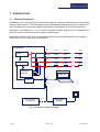
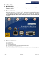
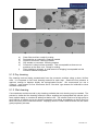
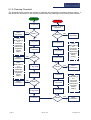
SmartScan
Product Manual
Document Ref:
3100-3002 Iss E
Document Date:
30th Aril 2013
Prepared by:
KMJ
Approved by:
RT
This information herein is the property of Smart Fibres Ltd and is to be held strictly in confidence by the recipient. No copy is to be made
without the written permission of Smart Fibres Ltd. Disclosures of any of the information herein is to be made only to such persons who
need such information during the course of their engagement or employment at Smart Fibres Ltd or under the written authority of Smart
Fibres Ltd.
Any patent applications, patents and/or design applications, registered designs or copyrights arising from or contained in the information
herein, shall be considered the property of Smart Fibres Ltd and as such are subject to the aforementioned obligation of confidence on
the recipient.
abcdef
Certificate No: LRQ 4003532
Smart Fibres Ltd · Brants Bridge · Bracknell · RG12 9BG · United Kingdom
Email: [email protected] · Web: www.smartfibres.com
Tel: +44 1344 484111 · Fax: +44 1344 486759
Directors: C Staveley · A Melrose · Registered in England: 3563533 · VAT Registration No: GB723426060
Registered Office: 141 Dedworth Road · Windsor · Berkshire · SL4 5BB · United Kingdom
1
2
Introduction.................................................................................................................. 3
1.1
Product Description .............................................................................................. 3
1.2
Packing List .......................................................................................................... 4
Safety Information........................................................................................................ 4
2.1
Safety Symbols..................................................................................................... 4
2.2
Laser Safety ......................................................................................................... 4
2.3
CE Compliance..................................................................................................... 4
3
Specifications .............................................................................................................. 5
4
Installation ................................................................................................................... 6
5
4.1
Mounting Details................................................................................................... 6
4.2
Optical Connections ............................................................................................. 6
4.3
Electrical Connections .......................................................................................... 6
4.4
Interrogator Status LED........................................................................................ 7
Maintenance ................................................................................................................ 8
5.1
Optical Connector Cleaning.................................................................................. 8
5.1.1
Inspection ...................................................................................................... 8
5.1.2
Dry cleaning .................................................................................................. 9
5.1.3
Wet cleaning.................................................................................................. 9
5.1.4
Cleaning Flowchart...................................................................................... 10
5.1.5
Cleaning tools.............................................................................................. 11
5.2
Interrogator......................................................................................................... 11
Document Revision History:
Issue
E (this document)
Issue Date
30th April 2013
D
31st March 2011
C
18th October 2010
B
1st September 2010
A
10th May 2010
Change
SmartSoft sections removed and now
contained in separate manual, (See 3100‐
3008)
Plug‐ins for Field Upgrades & NTP sync
option.
Added FBG spec to specifications
Include instructions for the time of flight
correction : 5.4.3 and 6.5 modified
Updated SmartScan Lite wavelength range
and scan frequency on specifications page
Modified in line with SmartSoft V2.00
Draft
18th September 2009
New document
Page 2
30th Aril 2013
3100-3002 Iss E
1 INTRODUCTION
1.1
PRODUCT DESCRIPTION
SmartScan is an ultra compact and robust interrogator for dynamic measurement of Fibre Bragg
Grating (FBG) sensors. This Wavelength Division Multiplexing (WDM) instrument is based on an
agile, tuneable laser source that enables high-resolution interrogation at multi-kHz frequencies.
SmartScan is available with 1, 2 or 4 optical channels; multiple sensors can be multiplexed on
each fibre without reducing acquisition speed or performance.
SmartScan connects to a host PC using standard Ethernet. Optionally SmartScan can integrate
directly with a PLC or other supervisory system.
SmartScan
CH1
FBG1
FBG2
FBGn
CH2
FBG1
FBG2
FBGn
CH3
FBG1
FBG2
FBGn
CH4
FBG1
FBG2
FBGn
Laser
Processing
Detection
Circuits
Host PC
RJ45
Comms
DC in
+9 to +36 VDC
15W supply
Or
Mains Power
Adaptor
Fig. 1 SmartScan System Diagram
Page 3
30th Aril 2013
3100-3002 Iss E
1.2
PACKING LIST
The SmartScan package should contain the following items as standard. If any items are missing
please contact Smart Fibres or your local representative immediately.
- SmartScan Interrogator
- Rugged carry case
- SmartSoft Installation CD
- Ethernet Cross-over cable
- Mains power adaptor and regional mains cable or DC power cable
2 SAFETY INFORMATION
2.1
SAFETY SYMBOLS
The following symbols may be present on the unit.
Symbol
Description
Laser Safety. Refer to user manual for safety instructions for
use.
Refer to user manual for safety instructions for use and
handling.
2.2
LASER SAFETY
Applicable Standard:
Laser Type:
Laser Class:
Max power:
Wavelength:
EN60825-1 (Safety of Laser Products)
cw
1M
2.5 mW
1528-1568nm
Refer servicing only to qualified and authorised personnel.
WARNING: Use of controls or adjustment of performance or procedures other than those
specified for the laser source may result in hazardous radiation exposure.
2.3
CE COMPLIANCE
Applicable Standards:
EMC Directive (EMC 89/336/EC)
EN61325-1 (Electrical equipment for measurement, control and laboratory use. EMC
requirements)
Page 4
30th Aril 2013
3100-3002 Iss E
3 SPECIFICATIONS
Measurement and Processing
Wavelength Range
40 nm (1528 – 1568 nm),
Number of Optical Channels
Bragg Grating Full Width Half Maximum (FWHM)
SmartScan Lite: 35 nm (1529 - 1564 nm)
1, 2, 3 or 4
Minimum >0.2 nm, > 0.5 nm recommended
Maximum Number of Sensors / Channel 1
16
Scan Frequency (all sensors simultaneously) 2
2.5 kHz, SmartScan Lite: 250Hz
Repeatability 3,4
< 1 pm
Wavelength Stability 4
< ±5 pm over operating temperature range, +/- 20 pm over 25 years
Dynamic Range
27 dB
Gain Control
On-board Processing
9 levels, per channel or per sensor, automatic or user controlled
5
On-board Data Storage
For conversion of measuring units and interfacing to client systems
5
Optional via USB memory stick
Mechanical, Environmental and Electrical
Dimensions
140x110x70 mm / 5.5x4.3x2.8”
Weight
Operating Temperature
0.9 kg / 2 lb
Std: -10 to +50 °C / 14 to 122 °F |
Comms Interface
Data Connector
Optical Connectors
Input Voltage
RJ45 standard
FC/APC 2.5 mm Ferrule diameter, alternatives on request
+9 to +36 VDC or 100 to 240 VAC via supplied mains adaptor
Power Consumption
1
Ext: -20 to +60 °C / -4 to 140 °F
Ethernet (UDP-IP), others on request
typ 7.5W, max 10W
Subject to spectral bandwidth restrictions
2
Higher frequencies achievable over narrower bandwidth, e.g. 20 nm at 5 kHz, 10nm at 10 kHz
3
Measured over 1 minute, no averaging, standard uncertainty (1 σ distribution)
4
Using FBG with recommended FWHM as stated
5 Optional extra
Page 5
30th Aril 2013
3100-3002 Iss E
4 INSTALLATION
4.1
MOUNTING DETAILS
Currently SmartScan is for bench top use; other mounting arrangements including DIN rail
available on request.
4.2
OPTICAL CONNECTIONS
SmartScan may have 1, 2, 3 or 4 FC/ACP connectors for connecting Single Mode
Fibres. These are numbered from the left as CH1, CH2, CH3 and CH4. Observe the
recommended connector cleaning practice described in Section 6. Connectors should only
be fastened finger tight, take care to correctly align the key-way when mating the
connectors.
4.3
ELECTRICAL CONNECTIONS
A = On/Off Switch
B = DC power Input
C = Power and Status light
D = RJ45 Ethernet Connector with built-in network status lights
E = Serial connector for diagnostics/servicing
There is also a USB port, which is currently inactive but may be used in future developments
Page 6
30th Aril 2013
3100-3002 Iss E
4.4
INTERROGATOR STATUS LED
OFF
Interrogator not powered or boot-up not complete
RED
System Error
GREEN
Interrogator booted an operational
Note, during power up the sequence is as follows:
1. LED Off
2. Power applied to Interrogator, LED remains off for approximately 10 seconds
3. LED Red briefly, Interrogator not ready
4. LED Green, Interrogator ready
Page 7
30th Aril 2013
3100-3002 Iss E
5 MAINTENANCE
5.1
OPTICAL CONNECTOR CLEANING
The use of optical fibre connectors requires some care if good results are to be obtained. The
core of the fibre is very small, typically 8 to 9 micrometres in diameter and even the smallest dust
particles, lint fibres or smears of oil can obscure it and cause optical losses. Scratches and chips
in the highly-polished end face of the fibre also result in poor quality, unreliable connections.
Therefore, it is important to develop good habits for handling and cleaning connectors. Ideally,
both sides of a connection should be inspected and cleaned before mating.
Connector tips can easily be damaged by hitting a hard surface. This can be avoided by always
keeping the plastic cover in place when not using or cleaning the connector.
A brief guide to good practise is given here. The interested reader will find further information from
Industry bodies. There are also some useful proprietary standards in the public domain, for
example:
•
•
•
AT&T: document ID ATT-TP-76461
Cisco: document ID 51834
JDSU: document ID IBYC – Fiber Inspection, Cleaning & Test
Note: These documents are identified for information only. No connection between any of the
named companies and Smart Fibres Ltd is intended or should be implied.
We understand that the first time user of a Smart Fibres product may not have all the correct
equipment to hand but cleaning and inspection tools are relatively inexpensive and help to ensure
continued correct operation of the interrogator. The regular user should make an effort to acquire
them and learn how to use them effectively
Some or all of the operations described below may be required to ensure that the fibre-optic
connection is free from contaminants. The order of operations is given in Section 5.1.4, ‘Cleaning
Flowchart’.
5.1.1 Inspection
It is highly desirable to inspect the end-face of connector ferrules (the white ceramic part) before
mating them, to ensure that they are clean and undamaged. If no inspection means is available,
you may skip this stage and proceed to a dry cleaning step, but be aware of the risk of making
lossy connections by mating ferrules that may be contaminated or scratched.
Remove the protective cap from the connector ferrule. Insert the connector into the fibre
inspection microscope and examine the end face. If the connector is of an angle-polished type, it
may be necessary to rotate it in order to see the end of the fibre clearly. Bulkhead connectors,
such as those in the front face of a Smart Fibres interrogator, can only be inspected using a fibre
video microscope with a suitable adapter. Typical views of a ferrule end-face are shown below:
Page 8
30th Aril 2013
3100-3002 Iss E
a)
b)
c)
d)
e)
f)
a)
b)
c)
d)
e)
f)
Clean fibre end-face, ready for mating.
Dust particles on connector. Cleaning needed.
Liquid on connector. Cleaning needed.
Oily streaks on connector. Cleaning needed.
Connector is clean but has scratches. This is acceptable as there are no
scratches on the fibre core. Ready for mating.
Fibre cladding is chipped. A small amount of chipping is acceptable but this
connector should be replaced.
5.1.2 Dry cleaning
Dry cleaning involves wiping contaminants from the connector end-face using a clean, lint-free
cloth. It is important to use fresh cleaning material for each wipe. Gentle but firm pressure is
required, enough to depress slightly the spring-loaded ferrule. We recommend you use a
‘Cletop-s’ type cleaner for free connectors and a ‘One-click’ type cleaner for bulkhead or other
recessed connectors.
5.1.3 Wet cleaning
If a contaminant resists removal by dry cleaning methods then wet cleaning may be needed. The
process is similar but the cleaning material is either supplied pre-impregnated with solvent (as in
some optical wipes) or a solvent is added just before use. The solvent must be of a high purity to
avoid leaving a residue and a dry cleaning operation must follow immediately so that it does not
have time to dry on the connector ferrule. Isopropyl alcohol is often used but there are also some
good proprietary solvents.
Page 9
30th Aril 2013
3100-3002 Iss E
5.1.4 Cleaning Flowchart
The flowchart below covers the process of cleaning and inspecting connectors before mating. It
also shows the escalation of the cleaning method from dry cleaning to wet cleaning with solvents.
Start
Finish
st
1 Inspection
Make
Connection
Clean?
Clean?
Yes
No
Make
Connection
st
1 Dry Clean
th
6 Inspection
Note:
Both sides of
the
connection
should be
cleaned and
inspected
before
mating.
nd
2 Inspection
Yes
th
5 Dry Clean
nd
Clean?
2 Wet Clean
No
Note:
Both sides of
the
connection
should be
cleaned and
inspected
before
mating.
Make
Connection
No
Yes
Note:
Both sides of
the
connection
should be
cleaned and
inspected
before
mating.
Make
Connection
Replace or repair
connector*
No
nd
2 Dry Clean
Clean?
rd
3 Inspection
Yes
Yes
th
5 Inspection
Note:
Both sides of
the
connection
should be
cleaned and
inspected
before
mating.
th
Clean?
4 Dry Clean
No
st
1 Wet Clean
rd
3 Dry Clean
Make
Connection
No
th
4 Inspection
Page 10
Clean?
30th Aril 2013
Yes
Make
Connection
3100-3002 Iss E
5.1.5 Cleaning tools
Fibre Inspection microscope
Battery-powered microscope with 200x
magnification. Requires different adapters
for different connector types. Must never be
used to examine ‘live’ fibres.
Cletop-s Cassette cleaner
Highly effective method of cleaning a free
connector ferrule. Contains a cassette of
anti-static cleaning cloth. Pressing the blue
lever exposes a fresh length of material. Not
suitable for wet cleaning.
‘One-click’ Ferrule cleaner
Required for cleaning recessed ferrules but
can also be used on free connectors.
Automatically wipes the ferrule end-face
when it is pushed into the connector
receptacle. Can be impregnated with solvent
for wet cleaning.
5.2
INTERROGATOR
The interrogator contains no user serviceable parts and should be returned to Smart Fibres UK or
their local representative for maintenance or repairs.
Page 11
30th Aril 2013
3100-3002 Iss E