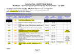
1
Technical Tips - FEEDER Module
MaxiMailer – Service Engineers’ Technical Tips Documentation – Jan 2007
The following documentation describes all MaxiMailer field issues and corrective actions.
Please refer to these documents before any service or maintenance is conducted.
Items highlighted thus are Jan 2007 additions.
INSERT FEEDER, TOWER FEEDER and Mark Reading Modules (1450, 1452, 1451 and variants)
Technical
Tip
Number
Page
Number
Main Area – Insert Feeder and Tower Feeder
(1450, 1452, 1451 and variants)
Date
Effective
from
Date
Effective to
Technical
Bulletins
Mandatory
()
Oct 03
Oct 03
Sept 04
Aug 05
-
Oct 03
Aug 05
-
Oct 03
Jan 05
-
Oct 03
Jan 05
-
Optional
-
-
-
-
FIELD
OPTIONS
-
Optional
-
(if applicable)
Field Options Summary Table
Ref. A-11
Ref. A-16
1-15
1-18
Ref. A-23
Ref. A-41
B-1
2-6
B-2
2-6
B-3
2-7
B-4
2-8
B-5
B-6
2-12
2-12
Noise from loose pins on gears.
Clutch Pins falling out during running causing loss
of drive.
Cover Interlocks – AC Motor fails to stop on
opening of the covers.
MaxiMailer Software/ Firmware versions
Lower conveyor assembly (A7036A) track belts
coming off
Feed shaft assembly - pin becoming loose and
cutting sensor ribbon cable.
Increasing the Pre-load of the Insert feeder
separator assembly to assist separation
Document detailing the removal of A7231A
Transport Roller Assembly from the Tower
Feeders.
Belt F5151A breaking on tower feeder
Problems running particular types of 4mm thick
booklets from the feeder
12/02/07
Page 2-1
June 05
-
FIELD
OPTIONS
Technical Tips - FEEDER Module
MaxiMailer – Service Engineers’ Technical Tips Documentation – Jan 2007
INSERT FEEDER, TOWER FEEDER and Mark Reading Modules (1450, 1452, 1451 and variants)
Technical
Tip
Number
Page
Number
Main Area – Insert Feeder and Tower Feeder
Date
Effective
from
Date
Effective to
B-6A
2-13
Jan 07
-
-
B-7
2-13
Oct 03
Mar 04
-
B-8
2-15
-
-
-
-
-
-
-
-
Jan 07
-
-
Adjusting the separator to suit the document
-
-
-
2-20
2-21
Spare Kit Part Numbers
MaxiMailer OMR Barcode Insert Feeder
Positional Specification
-
-
-
FIELD
OPTIONS
FIELD
OPTIONS
FIELD
OPTIONS
FIELD
OPTIONS
FIELD
OPTIONS
-
B-8A
2-15
B-9
2-20
B-9A
2-20
Z folded documents opening up during running
(Field option) – Jan 2007 updates.
Particular thick booklets need heavier rolling
backstop
Optional Rolling Backstop
B-10
2-20
B-11
B-12
B-13
B-14
B-15
2-23
2-24
2-25
Gear Noise
Miscellaneous Jan 2007 improvements
MaxiMailer ribbon cable sets now available as
separate items
Jan 07
Jan 07
Jan 07
-
-
-
(1450, 1452, 1451 and variants)
Improved feeding of Thick booklets – Jan 2007
updates
Red Loctite on Operating Handles that have
become loose.
Z – folded documents opening up during running
12/02/07
Page 2-2
Technical
Bulletins
Mandatory
()
(if applicable)
FIELD
OPTIONS
Technical Tips - FEEDER Module
MaxiMailer – Service Engineers’ Technical Tips Documentation – Jan 2007
Intentionally Blank
12/02/07
Page 2-3
Technical Tips - FEEDER Module
MaxiMailer – Service Engineers’ Technical Tips Documentation – Jan 2007
Field Options
Part
Number
Roller /
Separator
Type
Jog Tyre
Application
Qty
required
Description
D0052A
Relevant
Assembly
Number
N/A
Envelope
Feeder,
Insert feeder
2-off
(fitted on
the outer
wheels).
These tyres are standard on the envelope feed and
are used to provide improved grip and drive.
C8194A
A7267A
Slotted
Feed Tyre
Envelope
Feeder,
Insert feeder
6-off
This feed wheel has advantages when feeding
inserts with a powdery finish.
D0037A
A7268A
Silicon
Feed Tyre
Envelope
Feeder,
Insert feeder
6-off
These provide added grip on certain glossy
stationery.
C8193A
A7269A
Roller HIGRIP
EPDM
Envelope
Feeder,
Insert feeder
6-off
These provide high grip on certain glossy stationery.
12/02/07
Page 2-4
Technical Tips - FEEDER Module
MaxiMailer – Service Engineers’ Technical Tips Documentation – Jan 2007
Part
Number
Roller /
Separator
Type
Special
Insert
Separator
Assembly
Application
Qty
required
Description
A7174A
Relevant
Assembly
Number
A7174A
Insert Feeder
1-off
This version exposes more of the friction pad to the
insert pack and can help with forms that are proving
difficult to separate.
B7803A
N/A
Over-guide
Insert feeder
1-off
An over-guide is available to overcome feed
problems associated with peeling open of folded
documents on pick-up. This is a guide similar to the
one used to keep the envelope flap closed on the
envelope feeder.
D0059A
A7271A
Coated
Silicon
Feed
Wheel
Envelope
Feeder,
Insert feeder
6-off
These provide high grip on certain glossy stationery.
12/02/07
Page 2-5
Technical Tips - FEEDER Modules
B-1. Insert feeder Lower and Upper conveyor assembly (A7036A)
track belts coming off.
Problem resolved on machine (effective from Jan 05) replace ALL Aluminium 25T/20T
pulleys with Plastic 25T (F1375A) / 20T (F1374A) pulleys.
Clean ALL pulleys and idlers to remove the toner that has deposited onto the teeth form - do
not use grease. If problem persists replace ALL Aluminium 25T pulleys with Plastic 25T
(F1375A) pulleys.
B-2. Feed shaft assembly - pin becoming loose.
Problem resolved on machine (effective from Jan 05).
Check and ensure pin (E5078A) in the Envelope or Insert feeder Pick-up shaft is not working
loose - see below. If so, a dab of Green loctite can be applied and any excess cleaned off.
Pin (E5078A) in Envelope or
Insert feeder Pick-up shaft is
not working loose.
12/02/07
Page 2-6
Technical Tips - FEEDER Modules
B-3. Increasing the Pre-load of the Insert feeder separator
assembly – Field Option
The Separator Side Arm B8745A (operator and drive side) contains additional holes to
increase the pre-load of the separator mechanism. This may be required if you are
experiencing feeding, stream feeding or doubles issues with running particular stationary.
Increasing the pre-load will prevent the separator being pushed back easily.
Additional holes in the
separator side arm
(B8745A)
12/02/07
Page 2-7
Technical Tips - FEEDER Modules
B-4. Tower Feeder - A7231A Transport Roller Assembly – Removal
Instructions
This document summarises the procedure for removing the Transport Roller Assembly
A7231A from a MaxiMailer Tower Feeder (also available separately as K4039A).
Step 1
Remove the pins from the two clutches located onto the main 104T drive pulleys.
Step 2
Undo the fixing(s) on the bracket locating the two clutches and move it away from the chassis
(it is unlikely to come away completely unless the wiring attached to it is removed).
104T Drive Pulley(s)
Clutch Pin (Step 1)
Clutch Bracket (Step 2)
Step 3
12/02/07
Page 2-8
Technical Tips - FEEDER Modules
Undo the screw locating the main belt tensioner bracket and release the belt.
Step 4
Remove the 104T pulleys from the shafts.
Step 5
Remove the two gear idlers and 40T drive gear as indicated on the sketch below.
Safety Plate (Step 6)
Remove
Remove
Remove
Step 6
Remove the Safety Plate R2909A.
Step 7
Unclip the ribbon cable from connector J27 on the main board. Also unclip this ribbon from
the white plastic clip(s) on the main side plate.
Step 8
Undo the 4 screws (2 either side) locating the lower feed tray. Pull the tray back clear from its
position by as far as possible (taking care not to damage the reflective sensor that is attached
to the tray). If there is another unit down-stream of the Tower Feeder it will be necessary to
use a cloth to prevent the feed tray from scratching any covers.
Step 9
Remove the lower hopper feed rollers A7030A.
Step 10
Remove the upper Paper Eject Knob P2151E, drive pin and clutch from the operator side of
the machine.
12/02/07
Page 2-9
Paper Eject Knob &
Clutch (Stage 10)
Technical Tips - FEEDER Modules
Step 11
Unscrew and remove the Rear Tower Infill Cover B9086S (two screws in the side frames and
two screws in the upper feed tray). Note this cover has now changes – see TT note B-13 c.
Rear Tower Infill Cover
Step 12
Undo the four fixings locating the Transport Roller Assembly A7231A (two either side of the
machine) and withdraw it from the drives side plate.
Withdraw assembly
through this cut-out
When putting the machine back together steps 1-12 can be followed in the reverse order.
Please note that when replacing the Rear Tower Infill Cover B9086S it is possible to put it
back incorrectly. The following picture details the cover in its correct position.
12/02/07
Page 2-10
Technical Tips - FEEDER Modules
If a chassis fixing can be seen in this
area then the cover has been fitted
incorrectly. This fixing should be
located behind the cover.
12/02/07
Page 2-11
Technical Tips - FEEDER Modules
B-5. Tower Feeder Belt F5151A breaking
Problem resolved on machine (effective from June 05).
There have been instances of the main drive belt breaking on the tower feeder - this is
caused by the belt running on the flanges of the 2 belt idlers (Ref Service Manual page 4b12). These idlers have been replaced with part number A7273Ax2 per tower feeder.
New belt
idler
B-6. Problems running particular types of 4mm thick booklets from
the feeder – Field Option
There have been some instances where a 4mm booklet is difficult to feed into the deskew
transport rollers. If this has occurred, then carry out the following actions: 1) Ensure Deskew value is set to OFF. Note Double Document Detection must also be
turned OFF.
2) Green (G1111A) springs can be fitted onto the upper transport rollers (Deskew
rollers) to encourage feeding. Note, this may cause other issues – driving
3) The roller infeed guides (G6153A) can also be removed from Transport Roller
Assembly (A7033A) to prevent wedging of document.
12/02/07
Page 2-12
Technical Tips - FEEDER Modules
B-6A. Improved feeding of Thick booklets – Jan 2007 updates
There have been a number of improvements in this area , which consist of:
1 Roller Infeed Guide G6153A shortened to expose more nip roller surface
2 Nip roller springs changed to Spring Medium Pressure G1251A. Less force required
to separate nip rollers (standard feeders only).
3 Firmware changed to keep Feed Wheels driving longer (dependent on insert length) –
v.4.1.x.x.
4 Revised Backstop Roller assy gives ability to easily fit alternative rollers – see TT B9A.
5 Intermediate separator stop positions added between the current A, B, C and D
settings. This gives greater flexibility for inserts where the current settings are not
suitable
B-7. Red Loctite on Operating Handles
Problem resolved on machine (effective from Mar 04).
12/02/07
Page 2-13
Technical Tips - FEEDER Modules
B-8. Z – folded documents opening up during running – Field
option
If you are experiencing Z folded documents opening up, then the following can be trialled:1) fit green (G1111A) springs onto the deskew rollers (currently yellow).
2) set-up the separator gap to feed the above form (in position 'B') by adjusting the eccentric
(P2055A) on the adjustment bracket. Full instructions highlighted in Service Manual (section
3.2.3).
3) bend up overguide stop by approx . 30/40 degrees from its current position highlighted
below and fit the overguide (B7723A). This will stop the overguide going too far forward and
also support the z fold to sit behind of the side guides.
12/02/07
Page 2-15
Technical Tips - FEEDER Modules
B-8A. Z folded documents opening up during running (Field
option) – Jan 2007 updates.
Clarification on how to achieve this setup:1. Section B.8.2: As per Service Manual 3.2.3, unlock the gap adjustor and whilst the
separator adjustor bracket is set at position ‘B’, rotate the brass eccentric until you
achieve the following setting,
MANUALLY ROTATE FEED ROLLERS:
SET GAP SETTING SUCH THAT CARD
CARRIER DOCUMENT DOES NOT UNRAVEL
AS IT IS DRIVEN THROUGH SEPARATOR AREA
'LIGHT' PULL
SHOULD BE ACHIEVED
ON FORM WHEN SEPARATOR
SET AT CORRECT
POSITION
SEPARATOR ADJUSTMENT BRACKET:
ADJUSTED WHILST AT POSITION 'B'.
2. Section B.8.3: Fit the Overguide B7723A (including the plastic bearings E0214A)
onto the feed shaft. Modify the tag on the upper transport roller carrier (which acts as
a stop for the overguide) such that it sits in the following position,
45
°
7
40°
6
12/02/07
Page 2-16
Technical Tips - FEEDER Modules
Please note that if the overguide is allowed to pivot too far forward then the document
is more likely to unravel as it is wrapped around the feed roller. The ideal loaded
position is as shown below and as such it is best not to over-fill the hopper,
You may also find that the documents do not fan cleanly down the hopper during
running and as such it may not always be the top form that is fed into the separator,
resulting in a ‘bunch’ of documents being forced through the separator,
12/02/07
Page 2-17
Technical Tips - FEEDER Modules
If this occurs the addition of an abrasive material (i.e. 2 strips of ‘emery’ cloth, typically
one-inch wide), which runs from underneath the side guide and down into the
separator area may help. This abrasive material, which should be as thin as possible,
should help encourage the documents to fan in the correct orientation as they run
down the feed hopper,
12/02/07
Page 2-18
Technical Tips - FEEDER Modules
12/02/07
Page 2-19
Technical Tips - FEEDER Modules
B-9. Particular thick booklets need heavier rolling backstop – Field
option
A heavier roller backstop (part number TBA) can be fitted if experiencing feeding problems
with particular documents.
B-9A.Optional rolling backstops
The Rolling backstop has been revised to make it easier for assemble/disassemble.
Also, there are now optional heavier and lighter versions that can be fitted if
experiencing feeding issues. Note these options can also be fitted onto the feeder
modules if required.
Part numbers:
•
•
•
•
C3657A x2 – Backstop roller Acetyl
C9734A x1 – Roller bar
C3656A x2 – Optional heavier Backstop roller Aluminium
C3660A x2 – Optional lighter Backstop
B-10. Adjusting the separator to suit the document – Field option
If you are experiencing feeding problems from the insert feeder or tower feeder and tech tips
notes B3, B6, B8 and B9 have been initially carried out then the separator gap can be
adjusted to suit the document as outlined in the Service Manual (section 3.2.3).
B-11. Spare Kit Part numbers for the Feeder Modules Only
A0342A Feeder (1450) spares 230V
A0345A Feeder spares 115V
A0438A Tower Feeder (1452) spares 230V
A0439A Tower Feeder spares 115V
12/02/07
Page 2-20
Technical Tips - FEEDER Modules
B-12. MaxiMailer OMR Barcode Insert Feeder Positional
Specification
This document defines the label positions for OMR & Barcode marks on the MaxiMailer
OMR/Barcode Feeder. For the full specification of the OMR & Barcode functionality
please refer to the relevant company-wide technical documentation.
This document is for PFE use only. It may be subject to change. It should not be
reproduced without specific permission from PFE.
Label Positions – OMR
Distance from the lead edge of the document
19mm (¾") to the first mark
Datum
CL
12mm
Clear Space
to Gate Mark
Mark Spacing
1/8", 1/6", 1/5",
1/4", 1/3", 3mm,
5mm or 10mm
Direction of
Paper Travel
Clear Space
5mm
Clear Space
2.5mm
40mm
Mark spacing (Pitch)
Label Positions
– Barcode
is the distance
from
OMR marks may be
printed anywhere in
shaded area.
the top of one mark
to the top of the next
mark
Please note that only Horizontal barcode marks can be read.
Minimum mark
thickness
0.5mm
Minimum mark
width 8mm
Distance from the last mark to
the trailing edge of the document 10mm
12/02/07
Page 2-21
5mm Typ
95mm
Maximum
Length of
Reading Area
From Datum
Regardless
of Form
Length
12/02/07
8mm Min
Direction of
Paper Travel
6mm Min
Quiet
Zone
80mm Max Label Length
Horizontal Direction
6mm Min
Typ
6mm Min
Quiet
Zone
5mm Min
Datum
Technical Tips - FEEDER Modules
Page 2-22
110mm
Maximum
Length of
Reading Area
From Datum
Regardless
of Form
Length
Technical Tips - FEEDER Modules
B-13 Gear Noise from the Feeder modules
This has been pinpointed to the following parts:
1) Noise from 22XL (F1252A) pulleys on the lower conveyor assemblyA7036A.
Noise from 22XL
(F1252A) pulleys on
the lower conveyor
assemblyA7036A
Corrective action: Shim All four 22XL pulleys with G6028A.
Shim
12/02/07
Page 2-23
Technical Tips - FEEDER Modules
2) Squeaking gears – (vibration noise) from the compound gears next to the pick-up clutch as
shown below:Corrective actions: remove/clean gear and shaft then fit a shim (G6028A) behind the gear to
prevent any rocking movement.
Fit shim
behind this
gear
B-14 Miscellaneous Jan 2007 improvements
a) Side Guide Operator B9077A. On the Tower Feeder module the side guide is cut
away to improve operator access for loading.
b) The Brake Locators R2347A on the tower feeder have been strengthened.
c) Tower feeder infill cover changed from 1 to 2-piece construction for improved
service access.
d) Conveyor track shafts - removal of grooves to improve fatigue strength.
e) Punched arrow indicators added to identify sensors.
12/02/07
Page 2-24
Technical Tips - FEEDER Modules
A-15. MaxiMailer ribbon cable sets now available as separate items
Ribbons are now available separately.
182-549 Maxi FDR Ribbon Set
Now also available in the separate parts shown below:
182-549A - RIBBON 182-549 PART A
182-549B - RIBBON 182-549 PART B
182-549C - RIBBON 182-549 PART C
12/02/07
Page 2-25