1
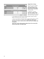
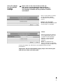
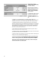
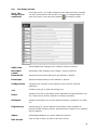
Table Of Contents 1 Introduction................................................................................ 3 1.1 Pictograms............................................................................ 3 1.2 Notes on the Use of this Handbook........................................... 4 2.Safety Notes................................................................................ 4 2.1 General safety notes............................................................... 5 2.2 End of Life............................................................................. 6 3. TECHNICAL SPECIFICATION........................................................ 8 3.1 Machine rating sheet............................................................... 8 4. Machine Layout Guide.................................................................. 9 4.1 Description of machine............................................................ 9 4.2 Parts identification.................................................................10 5. Operating Instructions.............................................................. 11 5.1 What’s in this Document.........................................................11 5.2 Starting the Operating Program...............................................12 5.3 The Run screen explained.......................................................13 5.3.1 To change the User........................................................14 5.3.2 To change the Job.........................................................14 5.3.3 To adjust the Envelope Inserter settings...........................15 5.3.4 To adjust the Document Inserter settings.........................17 5.4 The Setup screen..................................................................19 5.4.1 The Setup screen explained............................................19 5.4.2 The List Box.................................................................20 5.5 The OMR Code screen............................................................21 5.6 The Barcode/Labels screen.....................................................23 5.7 The Documents screen...........................................................25 5.8 The Envelopes screen............................................................27 5.9 The Configuration screen........................................................29 5.9.1 Configuring the inserter..............................................29 5.9.2 Setting the inserter options for the Inserter unit................30 5.9.3 Setting the document options for the Feed unit.................31 5.9.4 Setting the feed options for the Feed unit.........................32 5.9.5 Setting the module options for a Folder............................34 5.9.6 Setting the output options..............................................35 5.9.7 Setting the postage options............................................36 5.9.8 Setting the miscellaneous options....................................37 5.10 The Job screen......................................................................38 5.11 The Users screen...................................................................39 5.12 The Statistics screen..............................................................40 5.12.1 Filter.........................................................................40 5.12.2 View Summary...........................................................41 5.12.3 Current & Previous sessions..........................................41 1 5.12.4 Data Logs...................................................................42 5.12.5 Open Archive..............................................................43 6. Running The Job........................................................................ 44 7. Daily Post (Handfeed)................................................................ 45 8.Setting Up The Machine............................................................. 46 8.1 Loading the paper hoppers Insert Feeder (Single, tower, OMR/ Barcode)..............................................................................46 8.2 Loading the envelope hopper..................................................47 8.3 Setting the separator gap.......................................................48 8.4 Using the accumulator...........................................................48 8.5 Operator settable separator (Optional).....................................49 9. Operator Maintenance............................................................... 50 9.1 Clearing paper crashes...........................................................50 9.2 Cleaning rollers and sensors...................................................52 9.3 Maintaining the wetting system...............................................56 10. 2 Document Orientation Tables..................................................... 57 1 Introduction With this inserter you have an advanced, medium-volume folding and inserting machine. Its modular construction allows up to 8 feed units to be fitted, with a maximum of 17 feed trays. Its sophisticated software control optimises the order and flow of documents for collating at the insert head before insertion into the envelope. All fold and adjustments take place automatically according to the requirements programmed in by the operator. In order to ensure the long usage of this machine and its components, and above all the safe use of the machine, you must read and adhere to the operating instructions and safety notes. Always be aware of all warnings and notes that are mounted or noted on the machine itself. All persons entrusted with the handling of this machine must also be familiar with the operating manual. Save this handbook carefully, so that the information it contains may be available at all times. 1.1 Pictograms General Warnings Warning of danger from electricity or electrical shock Information / Note indicating important information regarding the handling of the machine. 3 1.2Notes on the Use of this Handbook This document contains all general information and explanatory text necessary in order to be able to carry out the operation of the machine. When some action is expected from the operator, this will always be explicitly stated, and where relevant, accompanied by an illustration or graphic. Always read through each step, so that you will obtain all of the necessary information. Do not anticipate what you believe will follow in the handbook: It will prevent you from making mistakes! Chronology and Reference This handbook is structured chronologically, and therefore ordered sequentially for the operationally ready machine. It assumes that the machine has been installed in the correct environment by an Authorised Service Engineer and that the operator or his or her supervisor has had a degree of operator training. When you are unfamiliar with the machine, it is best to read through the handbook from beginning to end. You will be guided step by step, and in this way you can easily and quickly have the machine in operation. If you are already familiar with the machine, it will make thing easy if you use this handbook as a reference work. 2.Safety Notes For your own safety and the operating safety of the machine, read the following notes carefully before starting your machine. Always be aware of all warnings and notes that are mounted or noted on the machine itself. Save this handbook carefully, so that the information it contains may be available at all times. The machine is of advanced construction and reliable in operation. Nevertheless, the device does present hazards when operated by untrained personnel. The same applies to use that is inappropriate and not in keeping with its intended purpose. In not adhering to this handbook, there is the danger of 4 • • • an electrical shock, injuries from the intake at the rotating rollers, damage to the machine. 2.1 General safety notes Caution! Please, read these notes with care. Save these instructions for later use. All notes and warnings found on the machine are to be followed. Installing the machine Important! The machine must be installed only by an Authorised Service Engineer. A safe, level position is necessary, when installing the machine, with sufficient space all round to operate it. The machine is to be protected from moisture. If moving the machine, ensure that the castor brakes are off, and push on the stand, not the machine. Ensure there is at least 1 metre of free space between the operator side of the machine and a wall or barrier. To provide access to the mains switch, the opposite side of the machine must be at least 150mm from a wall or barrier. Do not place surrounding furniture or other objects where your path may be obstructed. Electrical danger The machine may only be connected to a voltage of 230V/50Hz or 115V/60 Hz,depending upon model. The mains plug may only be connected with a socket having an installed protective contact! The protective effect will be compromised by the use of an extension line without a protective grounding conductor. All interruptions of the protective grounding conductor, within or outside of the machine, are prohibited. The device is double pole fused! When fuse failure occurs, electrical machine parts can still carry voltage. When making the connection to the mains power, be aware of the connection values on the nameplate. Inspect the voltage setting on the device’s power input module. Run the supply lines in such a way, that no-one may trip over them. Do not place any objects upon the supply line. When the machine is not in use over a long period of time, it should be disconnected from the power supply. In this way, damage would be prevented in the event of excess voltage. Protect the device from moisture. When moisture enters the machine, there is the danger of electrical shock. Never open the machine except the top cover. For reasons of electrical safety, the machine may only be opened by authorized Service Agents. Operating safety Never reach into the machine when it is running! This could only occur if a safety interlock were to fail. The danger of injuries exists, through pulling in and crushing on the rotating rollers. In addition, keep long hair and parts of loose clothing far from the machine in operation. If a safety interlock fails, your Service Agent must be contacted immediately! In order to prevent damage to the machine, only factory authorized accessory parts should be used. Cleaning the machine Prior to cleaning the exterior of the machine, it should be disconnected from the power supply. When cleaning the machine, do not use liquid or spray cleaners, but only a cloth dampened with water. Cleaning sensors When cleaning sensors use only non-flammable airdusters, eg. part number E0070A. Other types may use flammable propellants, which could result in fire or explosion. 5 Allow machine to checked be the by Service Agent In the following cases, the mains plug must be unplugged and the device left for the authorized Service Agents: • When the mains cable or plug is worn or damaged. • When water or other liquid has entered the device. • When the device does not function properly, in spite of following the instructions provided. • When the device has fallen down or the housing is damaged. • When there are noticeable differences in the normal operation of the machine. Spare Parts When repair work is carried out, only original spare parts or spare parts corresponding to the original parts may be used. Repairs Do not disassemble the machine any further than is described in this handbook. Other than the top cover, the opening of the machine by unauthorized personnel is not permitted. Repairs may only be carried out by an authorized Service Agent. Modification is not permitted: For safety reasons, your own reworking and modifications are not permitted. Please contact your Service Agent, for all questions relating to service and repair. In this way, you ensure the operational safety of your machine. 2.2End of Life The objectives of the European Community’s environment policy are, in particular, to preserve, protect and improve the quality of the environment, protect human health and utilise natural resources prudently and rationally. That policy is based on the precautionary principle and principles that preventive action should be taken, that environmental damage should as a priority be rectified at source. Separate collection of waste is the precondition to ensure reuse and recycling of waste that is generated at the disposal of electrical or electronic equipment and is necessary to achieve the chosen level of protection of human health and the environment in the European Community. More particularly, certain materials and components of waste electrical and electronic equipment needs selective treatment as their injudicious handling or disposing of on or into land, water or air would represent a major threat to the environment and human health. 6 In order to facilitate collection and treatment separated from normal domestic waste, electrical and electronic equipment is marked with the following logo: Do not mix with normal domestic waste. Please use the subjoined return or collection system dedicated to electrical and electronic waste. Equipment produced after August 13 2005 Not only are you by law not allowed to dispose of the waste equipment via other wastestreams, but we encourage you to actively contribute to the success of such collection and to the common good and better quality of life of present and future generations. For more information on the correct disposal of this product please contact your local dealer. 7 3. TECHNICAL SPECIFICATION 3.1 Machine rating sheet 1. CAUTION: In order to ensure correct safety and operation, this machine must only be installed and maintained by an authorized Service Engineer. 2. CAUTION: Should any cover or safety interlock be damaged, the machine must not be used until service repairs have been completed. 3. CAUTION: This machine must be earthed. The wire colours in the mains power cord are: (Green/Yellow 230v) (Green 115v) which must be connected to Earth (Ground). (Blue 230v) (White 115v) which must be connected to Neutral. (Brown 230v) (Black 115v) which must be connected to Live (Line). 4. CAUTION: 5. CAUTION: This machine is supplied with an unterminated mains cable for hard wiring or connection with a suitable 16A plug/socket conforming to IEC 60309. For continued protection against risk of fire, replace with same type and rating of fuse. The fuse rating/type for this machine is : T 6.3 A Amps 230Volts (Part No. 135-106). T 10 A Amps 115Volts (Part No. 135-110). 6. Model Details: Model Name: 140 series Model Number: 1430 Input Voltage: Input current: 230 Volts @ 50 Hz 115 Volts @ 60 Hz 3.5 Amps 7 Amps 75dBA 75dBA Sound Reading: (measured at a distance of 1 meter from the nearest cover and a height of 1.6 metres from the ground). 7.The use for this machine is for collating, folding and inserting documents into an envelope. 8. The weight of this machine is: 290 kgs (unpackaged) 400 kgs (packaged, with accessories) Based on a configuration 3 x Feeders and 3-Plate Folder Lifting or handling must only be carried out by competent persons using appropriate means. 8 4. Machine Layout Guide 4.1 Description of machine The function of the machine is to feed forms from a number of hoppers, fold them in either ‘C’, ‘Z’, ‘V’ or double forward fold and insert them into an envelope which is then sealed and ejected. Further form(s) may optionally be collated with the first form, either by folding together or collating on the track. Inserts (cards, cheques etc.) may also be collated on the track before inserting. The machine is OMR/Barcode compatible, allowing a group of forms to be collated in the accumulator prior to folding. Forms may be inserted without sealing the envelope for subsequent hand insertion of card, gift etc. Multiple insertions may also be used, ie. a preset number of forms (or combination of forms) are separately inserted into the collation pocket in the inserter head. There is a batch processing facility, allowing a preset number of cycles to be completed before the machine automatically stops. The machine consists of a number of modules, depending upon the build ordered - these modules are briefly described below: a) Inserter head - Collates all documents in a pocket before insertion, feeds the envelope, inserts the pack and seals the flap. b) Insert Feeder - Feeds shortform inserts (cards, cheques, booklets etc.) onto the track for subsequent insertion. Available as a single feeder with one feed hopper or a tower feeder with two feed hoppers. An OMR/Barcode version (with one feed hopper) is also available. c) Feeder Folder - Mounts on the track, either in conjunction with a tower folder (see below) or as the last station. Fitted with one feed hopper, and folds the same size stationery as the tower folder, but uses a 2-plate folding mechanism. An OMR/Barcode version (with one feed tray) is also available. c) Tower Folder - Mounts in the last station position and fitted with either one or three trays depending upon option. Includes a 3-plate folding mechanism, handfeed tray and an optional accumulator and/or single divert bin. The machine is equipped with PC controlled operating software from where jobs can be programmed and run. Jobs can be quickly switched from the main screen, and can also be ‘fine-tuned’ to accommodate a small change in job requirement. The number of jobs that can be programmed is limited only by the capacity of the PC. Input is via touch-screen monitor or keyboard/mouse. The machine is OMR and Barcode enabled, capable of reading a variety of different barcode symbologies. Other symbologies can be accommodated at special request. A daily post function can be used on the handfeed tray built into a tower folder as standard, and is an otional feature on a feeder folder. This allows groups of documents, stapled or loose, to be hand-fed; they will then be folded and inserted into an envelope. If other hoppers are loaded, further forms can be collated. An optional daily post function is also available on the feeder folder. No manual setting of the fold plates or envelope closer is required, these being adjusted automatically according to the settings in the selected program. An optional output conveyor can be specified, to replace the standard receiving tray. This is available in two lengths. 9 4.2 Parts identification Daily post tray PC control panel Tower feeder Tower folder (see below) Standard feeder Insert/collate area Envelope hopper Note: Station 1 is the first feed unit after the insert/ collate area. Filled envelope tray Storage cupboards (PC under insert head) Feed trays (either 3 or 1) Tower Folder Accumulator (optional) Forms diverter (optional) Accumulator sideguide 10 5. Operating Instructions 5.1 These Operating Instructions guide you through the stages of using the machine. The machine is entirely software controlled, with all operator functions being performed on the touch-sensitive control screen. Different levels of user access can be allocated to personnel so that, for example, configuration operations can be restricted to Supervisors, while operators will only have access to straightforward running of the machine. The sections of this document that relate to restricted access are clearly indicated. The Operating Steps The functions described in this document are: • The Run Screen from which you control the running of the machine. • The Setup Screen where you select items that need setting up. • The OMR Code Screen to allow you to define OMR marks for up to four reader heads. • The Bar Code Screen to allow you to define Barcode characters. • The Documents Screen for defining the forms or inserts to be used. • The Envelopes Screen for defining the envelope to be used. • The Configuration Screen where you set up the envelope inserter and feeder units to use the selected stationery. • The Job Screen to allow you to define a job name and associate it with a machine configuration. • The User Screen for creating operator names, and allocating a password and access permissions. • The Statistics Screen for viewing production data. • Setting up the machine for loading stationery etc. What’s in this Document On-line Help To provide assistance through the various operating screens, there will always be a ? symbol available. Click on this to display a popup box detailing further information for the area of the software you are using. 11 5.2Starting the Operating Program When you first start the operating program, you will be presented with the Run Screen, shown below and described in detail on the following page. The program will start with the last used operator and configuration, as shown at the top of the screen. To log on as another user. press the ‘User’ button and select one from the list. Enter the password, either by typing it in, or use the on-screen keyboard and press return (note that the password is case-sensitive). Assuming the correct password has been entered, the Run Screen will be available for use, as shown on the following page. User button Note: New operators and passwords can be only be entered or edited by authorised personnel with Supervisor access. This is detailed in section 5.11 ‘The Users Screen’ on page 39. 12 5.3 The Run screen explained Current time and date From this screen, you run and stop the machine and control the speed. It is also possible to change the selected user, change the selected job and enter Edit Configuration (authorised personnel only). Select user Machine graphic Reset count Output rate indicator Speed control and indicator Select job Autoend Double document calibrate Exit to setup screen Flush Process one cycle Exit software Run button Stop button To change the current user or job, click on the buttons and you will be presented with a list of all those that have been created, and allow you to select any one. Note that to change to a different user will require the appropriate password to be entered. To view and adjust the settings for the envelope and document inserters, click on the relevant part of the machine graphic (see the following page for details). 13 5.3.1 To change the User Click on the Select User in the logon box to view the list of user. To change to a different user, click on the name and enter the password - you cannot change the user unless you know their password (note that the password is case-sensitive). When changed, you will see the new user name at the top of the Run screen. To create a new user, The Setup Screen must be entered (see page 19). 5.3.2 To change the Job Click on the Select Job button to view the list of jobs. To change to a different job, click on the name and you will see the new job name at the top of the Run screen. To create a new job, The Setup Screen must be entered (see page 19). 14 5.3.3 To adjust the Envelope Inserter settings Note: Click on the ‘Unit’ button in the top left corner to toggle between fine tuning for unit and hopper. Unit Fine Tuning Click on the envelope inserter on the machine graphic to display the fine tuning screen. Click on Hardware Fine Tuning to display further information. You can select: a: The width of the collate pocket guides. b: The overall width of the insert fingers. c: The time allowed for the flap to seal before the envelope is ejected. d: Adjustment of the point at which the wetter beam drops to wet the flap. +ve increases wetting in 1mm steps (moves start point towards insertion area). e: Adjustment of the point at which the wetter beam lifts. +ve increases duration, ie. a greater length of flap is wetted befor the beam is lifted. f. Adjustment of the amount of envelope travel into the sealing rollers. +ve = further forward, away from exit direction. g. Adjustment of the envelope stop position for insertion. +ve = further forwards, towards exit direction. h. Adjustment of the amount of insertion of the insert pack into the envelope. +ve = further forwards past the flap crease. i. Adjustment of the amount of envelope foward travel after flap wetting, before reversing to enter the sealing rollers. +ve = further forward into the output rollers, towards the exit direction. When all adjustments are complete, click on the ‘Unit’ button for hopper settings, as described opposite. Important: All fine adustments apply only to the current job and will not affect any other jobs. 15 Hopper Fine Tuning From here you can adjust hopper settings. Click on the inserter hopper, then Document Fine Tuning to display further information. You can select: a: Whether or not the envelope is sealed. Select ‘Off’ if, for example, later hand insertion of an insert or other item will be required. b: The setting of the amount of envelope deskew required. Note a higher level will slow the machine more. c: Click on the button and adjust width, depth and flap depth if actual envelope varies from the settings shown.Warning: if the same document is used on other jobs as well, the same settings will be applied. Important: All fine adjustments apply only to the current job and will not affect any other jobs. 16 5.3.4 To adjust the Document Inserter settings Note: Click on the ‘Unit’ button in the top left corner to toggle between fine tuning for unit(shown here) and hopper (shown overleaf). The settings available will vary between feeders and folders. Click on the feeder or folder on the machine graphic to display the fine tuning screen. Feeder (of any type) No fine tuning of the unit part of the feeder is available Tower Adjust the address position if it is appearing too far up or down in the envelope window. +ve moves the address further up the window. Note: the address can also be adjusted in ‘Module Settings’ in the Configuration screen (see page 34). Whichever was adjusted last will take precedence. Important: All fine adjustments apply only to the current job and will not affect any other jobs. 17 Hopper Fine Tuning (Feeder and feeder folder, or tower folder) From here you can adjust hopper settings. Click on the appropriate hopper, and on Document Fine Tuning to display further information. You can select: a: Whether the unit is turned on or off. Select ‘Off’ if, for example, you wish to leave the hopper loaded, but temporarily disable it for the job. b: Whether or not doubles detect is enabled. Select ‘Off’ if, for example, the documents being run are substantially different from the calibration document, such as abnormally dark with heavy printing. c: Separator Position (feeder or tower feeder only): if you select a different setting from the one displayed (as calculated by the software) ensure the physical separator is set to the same setting, or a warning will be flagged with the first insertion cycle only. Note: this setting is duplicated in the ‘Configuration’ screen (see page 29). Whichever is set most recently takes precedence. d: The setting of the amount of document deskew required. Note a higher level will slow the machine more. e: Calibrate Reader: Only available if OMR head is fitted. Click the button and follow the instructions for calibration. f: Reader On/Off: Only available if a barcode head is fitted. Switching the reader on or off is required when aligning. g: Click on the button and adjust width and depth if actual document varies from the settings shown.Warning: if the same document is used on other jobs as well, the same settings will be applied. Important: All fine adustments apply only to the current job and will not affect any other jobs. 18 5.4 The Setup screen 5.4.1 The Setup screen explained From this screen, you make changes to the machine setup. Changes can then be saved and will remain until they are changed again. To enter the screen, click the setup button on the Run screen. OMR Code Allows OMR mark settings to be created, viewed or altered. Barcodes/ Labels Documents Allows Bar Code settings to be created, viewed or altered. Envelopes Allows envelope settings to be defined or altered. Configuration Configure the machine for all settings to use with the selected stationery Job Create a new job, or alter an existing one. Users Allows a new user to be added, and a password and permissions to be set. These can be also be altered for existing operators. Statistics Displays information on current machine settings, production run data etc. Engineering Allows testing of various parts of the machine. Only available to personnel with engineer access, and described in detail in the machine Service Manual. Admin Allows administration of various machine functions. Run Screen Click on this to take you back to the Run Screen. Allows form and insert settings to be defined or altered. 19 5.4.2 The List Box Click on any of the buttons on the Setup screen to display a list box. Shown left is the list box for the Document, and is similar for all of the buttons on the Setup screen. The list box shows all of the setups that have been defined so far. Select any of the setups shown and this can then be edited, copied or deleted by clicking on the appropriate button at the bottom of the box. New setups can also be created by clicking on the New button, and the newly created item can then be edited as required. Note that each name is allocated an ID number by the software, this being appended to the name. You can sort the list by ID or name, and if the list is long and a scroll bar appears, you can also search the list by name or ID using the buttons at the bottom. A filter can also be applied, to list only names or IDs containing criteria, such as a keyword or a part of it. When either the New or Edit buttons are clicked, the edit screen for that particular setup is displayed. These are explained in detail on the page indicated below: List Box OMR Code: Page 21 Barcode/Labels: Page 23 Documents: Page 25 Envelopes: Page 27 Configuration: Page 29 Job: Page 38 Users: Page 39 If any changes are made to the list box (ie. if an existing item is copied or deleted), the Save button will be active.Click on this to save the changes, and click Exit. Note that if an item is edited,Changes will be saved on that particular edit screen,and the Save button will remain dimmed. Warning!! For the ‘OMR Code’, ‘Bar Code’, ‘Documents’ and ‘Envelopes’ list boxes, do not delete a setup that is currently used in any configuration. If you do, the configuration that uses the setup will be substituted with the factory configuration named ‘Default Config’, which cannot be deleted or edited (for further details of Configurations, see page 29). 20 5.5 The OMR Code screen From this screen you can edit the OMR setup selected in the List Box, or click on ‘New’ if creating a new setup. The setup name and all OMR settings can be changed as required. Editing the setup name. Click on OMR Name and edit the name as required, either by typing it or by using the on-screen keyboard. Any changes made here will be reflected in the OMR Code list box when the OMR screen is saved and exited. Warning! Do not delete an existing setup if it is used in a current job. If you do, the factory default will be substituted. Editing the Set the Definition mode (see below), Code type (1-track or 2-track), Number of marks, Gate position (which edge of the paper the gate mark is parallel to settings. in relation to the address), Parity, First mark position according to the marks you are using and their printing on the stationery, Security Count direction and Security Count start (whether 0 or 1). Note that ‘Fixed’ is currently the only available option for pitch. Definition mode: Options are As printed / As fed. If ‘As printed’ the software will adjust for the mark direction whichever way round the paper is fed, and whichever way up it is loaded in the hopper. If ‘As fed’, it must be in the direction and orientation as specified in the unit settings in ‘Configuration’ – this mostly applies to legacy jobs. 21 Also set the Pitch, Gate position from Top of Form, Leading & Trailing margins (allowable tolerance for printed mark set to ‘drift’ and still be read), Divert oversize group (Y/N), Divert blank sheet (Y/N) and Address on every page (Y/N). Now select each OMR mark position button and enter the type of mark for each position, according to the marks you are using. Note: Prior to running a new or edited OMR setup using a SICK read head, the machine must first be calibrated by an engineer. This is not necessary with an MS3 reader. Note also that a SICK read head is available only on a Mark Reading Feeder. After making any changes, click the Save button at the bottom of the screen, and then the Exit button to return to the list box. The machine is now ready to use OMR reading and the setup you have created can be be selected for use in the Document screen. 22 5.6 The Barcode/Label screen From this screen you can edit the barcode or other ID label setup selected in the list box (see 1.2) or click on ‘New’ if creating a new setup. The setup name and all label settings can be changed as required. Editing the setup name. Click on Barcode name and edit the name as required, either by typing it or by using the on-screen keyboard. Any changes made here will be reflected in the Barcode list box when the Barcode screen is saved and exited. Editing the The buttons below Name relate to label settings and other non-BCS character functions. These are briefly described below: settings for non Definition mode: Only ‘As printed’ is available. BCS Number of characters in label: Up to max. 25 for BCS system. characters. Label machine control: The type of control system the machine will use to decode the label. Options are: Standard BCS (default) / Neopost 3 / Customer ID 3 of 9 / Numeric 2 of 5 / Last page custom 1 / Custom control 2. For all except Standard BCS, the Technical Support department must be consulted. Symbology: The code type of the label being read. Options are Default / Code 2 of 5 / Code 3 of 9 / Code 128 / 2D Datamatrix. Grouping: Select whether the group mark is End of group, First of group or Label on first page only (label printed on first page of group, but not subsequent pages). Good decode reads: Set the maximum number of good reads required before label is accepted. Set to low number if print quality is poor. 23 Security check: Used as a further method of security checking, additional to, or instead of using security BCS character. Select the character type to be used for checking (not used for MS3 reader). Data log enabled: If selected, a record of the movements of each group will be retained in a log file which can be viewed later in the Statistics screen. This data can then be used to compare the original number of documents with the number of processed envelopes. Choose whether to log from the label on the first page of a group, or the last. For details of Data Logging and the Statistics screen, see the 100/140 Operator Manual. Divert oversize group: If set to ‘Yes’, groups that are too large to fold will be fed into the divert tray (if fitted) without stopping the machine. If no tray is fitted, the machine will stop with the group in the accumulator. Divert blank sheet: As above, but applying to sheets with no label. Data logging characters: If data logging is being used, click on and enter the start character position and number of characters. See also page 38. Customer ID characters: Customer ID can be used for grouping, as an alternative to the Grouping character. Each form within a group is printed with the same character(s), with each group using a different character(s). Enter the start character position and number of characters. Editing the settings for BCS characters. Click on and enter the start position and character length of each function, either by typing it in the ‘Enter Value’ box, or by using the on-screen keypad. Number 1 is the first mark from the leading edge. ‘0’ (zero) means that character is not used. Note: a minimum of 4 characters must be used. See also ‘100/140 Barcode Specifications’. Security Form sequence within a Job: This is used to ensure that forms are processed through the inserter in the same order that they were printed, and that there are no missing forms. This is achieved by coding each form as it is printed with the alphabetic characters A,B,C......Z. The sequence then restarts at A again. When the forms are read by the barcode reader any deviation from the correct order is detected and an error produced. Set the start character position, and whether Incrementing (A - Z), or decrementing (Z - A). Form sequence within a Group: As above, but A,B,C.....Z are printed on each form within the group, then repeated for the next group. Note: if both Job and Group security are used, Direction must the same for each. After making any changes, click the Save button at the bottom of the screen, and then the Exit button to return to the list box. The machine is now ready to use Barcode reading and the setup you have created can be be selected for use in the Document screen. 24 5.7 The Documents screen From this screen you can edit the Form/Insert setup that was selected in the list box (see page 20) or click on ‘New’ if creating a new setup. The setup name and all form or insert parameters can be changed as required. Editing the setup name. Click on Name and edit the name as required, either by typing it or by using the on-screen keyboard. Any changes made here will be reflected in the Documents list box when the above screen is saved and exited. Warning! Do not edit the name for a Document currently used in any configuration. If you do, the factory default document ‘A4’ will be used instead. Editing the Icon: Select the icon from a preset list - this icon that will then appear in the graphic on the Configuration screen (see page 29). settings. Form type: Select the form type from a preset list. Width/Depth/Paper Weight: Click on the appropriate button and enter the required setting for the form or insert width, depth and weight (in the units shown) - see also Thickness & True Weight below. Pre-Folded Leaves: If the insert consists of more than one leaf (eg. a ‘Z’ folded flyer), click the button and enter the number of leaves. Thickness: If the insert is a booklet or other thick material, click the ‘Computed’ button to uncheck the box, and then click the ‘Thickness’ button. Enter the required figure in mm. Note that if this function is used Paper Weight will not be active. 25 Editing the True Weight: This shows the weight of the document or insert in the units shown, and is linked to Thickness above. To enter a known weight, click settings. the ‘Computed’ button to uncheck the box, and then click the ‘True Weight’ (contd.) button. Enter the required figure in the units shown. Note that if this function is used Paper Weight will not be active. The true weight need only be entered if Postage Rates are being used (see page 36). OMR Name: Click this button if you are using OMR, then click the Name button and select an OMR setup (see page 20 for defining OMR setups). Label Name: Click this button if you are using barcodes or other labels, then click the Name button and select a label setup (see OMR/Barcode User’s Manual for defining barcode setups).Note: OMR or Barcode reading are optional features. X / Y / Lx / Ly: Specify the X and Y dimensions to the centre of the marks or label, as indicated in the graphic. Specify the length of the marks or label for vertical (Ly) or horizontal (Lx) reading. Document ID: Optional Feature. Used to verify that the correct stationery is loaded into the correct feed unit. If using this feature, set ‘Doc ID Mode’ to ON and define the alpha-numeric characters being used for the ID. Note that the start position and length of the characters must be set in the Barcode/ Label screen. Document Address: If this is the address document, click the ‘Address Position’ button and select the position that best describes the location of the address - this will be used by the software to determine the type of fold and orientation of stationery. Note that the left/right location of the address is not stated, as this will be determined by the printed address matching the lateral position of the envelope window. If it is not the address document, select ‘None’. Click the ‘Save as Default’ button if you wish this to be the setup that new documents will default to. When all editing is complete, click the Save button at the bottom of the screen, and then the Exit button to return to the list box. Notes: 1. Minimum document width in the pack (including inserts) must be no smaller than the maximum document width by more than the following: Minimum document width = (Maximum document width/2) + 58mm. eg. if maximum document = 210mm, minimum document width = (210/2) + 58 = 163mm minimum. 26 5.6 The Envelopes screen From this screen you can edit the Envelope setup that was selected in the list box (see page 20) or click on ‘New’ if creating a new setup. The setup name and all envelope parameters can be changed as required. Editing the setup name. Click on Name and edit the name as required, either by typing it or by using the on-screen keyboard. Any changes made here will be reflected in the Documents list box when the Documents screen is saved and exited. Warning! Do not edit the name for an Envelope currently used in any configuration. If you do, the factory default document ‘DL’ will be used instead. Editing the Icon: Select the icon from a preset list - this icon that will then appear in the graphic on the Configuration screen (see page 29). settings. Width/Depth/Paper Weight/Flap: Click on the appropriate button and enter the required setting for the envelope’s width, depth, weight (in the units shown) and flap length - see also Thickness below. Thickness: If the envelope is of very thick material or of unknown weight, click the ‘Computed’ button to uncheck the box, and then click the ‘Thickness’ button. Enter the required figure in mm. Note that if this function is used Paper Weight above will not be active. 27 Editing the True Weight: This shows the weight of the envelope in the units shown, and is linked to Thickness described on the previous page. To enter a known settings. weight, click the ‘Computed’ button to uncheck the box, and then click the (contd.) ‘True Weight’ button. Enter the required figure in the units shown. Note that if this function is used Paper Weight will not be active. The true weight need only be entered if Postage Rates are being used (see page 36). Amount of wetting required: Different envelope types may require a greater or lesser amount of wetting for an effective seal. If you wish to change from the default setting of 3, click the appropriate button where setting 1 is the least, 4 is the greatest. OMR Name: This function is not available for envelopes. Label Name: Click this button if you are using barcodes or other labels for verification checking at output, then click the Name button and select a label setup (see OMR/Barcode User’s Manual for defining barcode setups). Note that the label can be printed either on the document (for reading through the window), or on the envelope. Note: OMR or Barcode reading are optional features Click the ‘Save as Default’ button if you wish this to be the setup that new envelopes will default to. When all editing is complete, click the Save button at the bottom of the screen, and then the Exit button to return to the list box. 28 5.9 The Configuration screen From this screen you edit configurations that were created in the List Box after clicking the ‘Configuration’ button in the Setup screen (see page 19) or click on ‘New’ if creating a new configuration. A configuration applies the settings to be used for the envelope inserter and all the stations fitted, which is then associated with a Job (see page 38). You can rename a new configuration by clicking on the Name button and editing as required, either by typing or by using the on-screen keyboard. Warning! Do not change the name of an existing configuration that is associated with a current job. If you do, the factory configuration ‘Default Config’ will be substituted. 5.9.1 Configuring the inserter. Click the upper icon on the ‘Head’ part of the graphic (showing the envelope icon). This displays the list of available envelopes to allow you to select one (see page 27 for creating Envelopes). If the machine has more than 6 stations, use the scroll arrows to move sideways. Select the required envelope and click ‘Ok’. Note: An error will occur if an envelope that is used in any configuration has been deleted from the list box in the Setup screen (see page 19). 29 5.9.2 Setting the inserter options for the Inserter unit Click on the bottom section of the Inserter (showing the unit icon), and the following dialog box appears: Select ‘Save as Default’ to make this the default for all new setups. These settings then apply to ‘Load Default’ Seal Mode: Options are Off / Always / Unseal OMR Select / Off Flap Open (if ‘Off’ is selected, flap is closed without sealing). 30 Deskew: The setting of the amount of envelope deskew required. Note a higher level will slow the machine more. Item ID: If available for setting must be set to Item ID 1. 5.9.3 Setting the document options for the Feed unit Click the upper icon on one of the numbered units (showing the document icon. This displays the list of available documents to select (see page 25 for creating documents). If the list is long, a ‘Find’ box will appear to enable you to search the list using keywords. If more than one incidence of the search result occurs, the ‘Next’ and ‘Previous’ buttons will be active. Select the required document and click ‘Ok’. Note: An error will occur if a document that is used in any configuration has been deleted from the list box in the Setup screen (see page 19). 31 5.7.4 Setting the feed options for the Feed unit Click on the lower icon of the numbered feed unit (showing the unit icon), and the following dialog box appears: Note that the options in the dialog box may vary from those shown, depending on whether the unit is a feeder or a folder. Select ‘Save as Default’ to make this the default for all new setups. These settings then apply to ‘Load Default’ Address Carrier: Select whether or not this is the address document. Note: this can also be selected from ‘Miscellaneous’ (see page 37). Whichever is set the later takes precedence. Feed Control Mode: Options are: Off / Feed Always / OMR or Barcode Select (the latter only available if unit is OMR/Barcode enabled). See OMR/Barcode User’s Manual for defining barcode setups. Note: OMR or Barcode reading are optional features. Fold Mode: (Tower folder only) Options are: Singly / Together / Via accumulator (the latter is only available if the unit has an accumulator fitted: if so, forms will group in accumulator first before folding.only). Form Count: Only available if ‘Mark reading’ is Off. If multiple forms are required, set this to the required quantity. Note: ensure that the maximum fold capacity is not exceeded. Reader (Head) ID: Only available if ‘Mark reading’ is On. Options are Reader (Head) 1 / Reader (Head) 2 / Both readers. Only available if two read heads are fitted. Mark Reading: Only available if unit is OMR/Barcode and a marked document is selected. Options are: Off / OMR marks / Barcode labels / 2D Datamatrix / OCR. Thickness Doubles: Set to ‘Off’ if, for example, the documents being run are substantially different from the calibration document, such as abnormally dark with heavy printing. Deskew: Set the amount of envelope deskew required. Note a higher level will slow the machine more. 32 Item ID: Options are: Auto / Nos. 2 - 17. Use ‘Auto’ unless select feed marks are being read; ‘Item ID’ then allows a number to be assigned to each unit to identify with the select feed mark. Default Separator Position: Only available on feeder or dual feeder and is a read-only display. Indicates the separator position calculated by the software. If the physical separator is set differently from this, a warning will be flagged for the first insertion cycle only. Separator Position: Only available on feeder or dual feeder. If you select a different setting from the one displayed in ‘Default Separator Position’ (see above) ensure the physical separator is set to the same setting, or a warning will be flagged with the first insertion cycle only. Note: this setting is duplicated in the ‘Fine Tuning’ screen (see page 18). Whichever is set most recently takes precedence. Cascading: Feeds from previous or next unit if feeder runs out of inserts. Settings available will depend upon hardware fitted and location of hopper. ‘Above’ and ‘Below’ apply to multi-hopper units. ‘Left’ and ‘Right’ apply to single-hopper units as viewed from the operator standpoint. 33 5.9.5 Setting the module options for a Folder If the unit is a tower folder or feeder folder, click on the uppermost section of the graphic (above the document icon), and the following dialog box appears: Select ‘Save as Default’ to make this the default for all new setups. These settings then apply to ‘Load Default’ Address position: Options are: Top / Middle / Bottom. Will apply to the hopper with the address-carrying document. Note: the address can also be adjusted in ‘Document Inserter Settings’ (see page 17). Whichever was adjusted last will take precedence. Feed Orientation: Options are Face up / Face down / Not important. Document Orientation: Options are Head first / Feet first / Not important. Fold Type: Select from a preset list, or Custom. Fold Lengths: Allows adjustment of the fold panels (note that fold plate lengths will adjust accordingly). Caution: inappropriate length settings could result in operating problems. Folded Length (mm): Allows adjustment if the actual folded length differs from the longest panel in Fold Lengths above. Address adjust: Adjust the address position if it is too far up or down in the envelope window. +ve moves the address further up the window. Max. Fold (forms): Sets the maximum number that can be grouped in the accumulator for folding together. Groups larger than this will be split, each section containing no more than Max. Fold. 34 5.9.6 Setting the output options Ensure that the Output tab in the configuration screen is selected. This section allows you to set up batching on the output conveyor (where fitted). Note: This screen will only be available to personnel with Supervisor access. This option is only available if a conveyor is fitted. Select ‘Save as Default’ to make this the default for all new setups Envelope batching If batching is used, the machine will either stop, or wait for a predetermined time period to allow removal of envelopes before restarting. To use batching, press the Output Conveyor button and select ‘Batch on’. Press the Control button to display the settings dialog, as shown above. The only Quantity mode available is ‘Envelopes count’. Set the required quantity either by typing it in or using the on-screen keyboard. For Control mode, select ‘Auto-restart’ (machine will pause for a set length of time and then restart - see below for ‘Pause time’) or ‘Pause’ (machine will stop and will only restart when the Run button is pressed). Jog step allows a gap between envelope batches to be set on the conveyor. The units shown are multiples of the envelope overlap, as adjusted by the knob on the conveyor. This means a suitable gap can be set without disturbing the knob. Pause time is the number of seconds before the machine auto-restarts. After making any changes, click the Save button at the bottom of the screen, and then the Exit button to return to the list box. 35 5.9.7 Setting the postage options Ensure that the Postage tab in the configuration screen is selected. This section allows you to define weight groups for setting different postage rates. The filled envelopes can then be diverted to different locations, according to the weight range that they fall within. If you will not be using postage rates, these settings can be ignored. Note: This screen will only be available to personnel with Supervisor access. Select ‘Save as Default’ to make this the default for all new postage setups Setting the weight group thresholds Setting the postage rates 36 There are four weight groups, each one defining a range with a lower and upper weight, and a postage rate to be set for that range. The upper weight that you set for each group will automatically appear as the lower weight for the following group, enabling an ascending scale of postage rates to be set for the four groups. To set the threshold for the first group, click the Weight Group 1 button and enter the upper weight of the range in grams. Press ‘Enter’. To set the postage rate for Group 1, click the Postage button, and enter the rate for that group. Press ‘Enter’. Repeat the above steps for the remaining groups (if required). Note: The weight of the filled envelope is determined by the weight of each inserted document, and the envelope. These are set in the Document and Envelope options in the Setup screen (see pages 25 & 27). 5.9.8 Setting the miscellaneous options Ensure that the Miscellaneous tab in the configuration screen is selected. This section allows you to select the required station for data logging (where used), and also for the address carrying document. Note: This screen will only be available to personnel with Supervisor access. Setting the datalog unit If you are using datalogs, set the unit you wish to use to record the log from by pressing ‘Logging from’. By default, this will be the prime unit. See page 42 for further details of datalogs. Address Carrier This allows you to select the unit that carries the address document (usually the prime unit). Note: this can also be selected from ‘Feed options for feed unit’ (see page 32). Whichever is set the later takes precedence. Confirm Calibration Select ‘No’ if you wish the machine to continue running after a calibration cycle is performed (by default, machine will stop and await confirmation of envelope contents). After making any changes, click the Save button at the bottom of the screen, and then the Exit button to return to the list box. 37 5.8 The Job screen From this screen you can edit the job that was selected in the list box (see page 20), or click on ‘New’ if creating a new job. The job name can be changed and/or a different configuration associated with it. Editing the job name. Click on Job Name and edit the job name as required, either by typing it or by using the on-screen keyboard. Any changes made here will be reflected in the Job list box when the Job screen is saved and exited. Click on Configuration and select an existing one from the list, if any. Selecting a configuration To create a new configuration, see ‘The Configuration Screen’ on page 29. Logging OCR data Click on Log OCR data if you are using an OCR scanner on the output and need to log the data gathered. Select ‘On (CommPort)’ if you wish to log data via the PC port. Select ‘Display verification read’ to display data on the Run screen as well as log to file. The file will be stored in the Data\DataLogs directory on the hard disk, and will take the format ocr_<Jobname>_<Date>.txt (‘ocr’ will vary for different data types). Late divert Set this to ‘Yes’ to use customer’s own data file to divert using the ID field label instead of the Divert BCS Character. Set to ‘On’ to divert for this job only, or set to ‘All’ to divert on occurrence of label in any job. Note that the Divert BCS character can also be used in conjunction with ID field label. Checking Not currently used. 38 5.9 The Users screen From this screen you can edit the user that was selected in the list box (see page 20), or click on ‘New’ if creating a new user. The user name, password and access levels can be changed. Editing the password. Click on Password and edit the password as required, either by typing it or by using the on-screen keyboard. This is the password that must be entered when the user is selected from the Run screen. Note: the password is case-sensitive Editing the user name. Click on User name and edit the name as required, either by typing it or by using the on-screen keyboard. Any changes made here will be reflected in the User list box when the Users screen is saved and exited. Setting the rôles Check the boxes as required to set the rôles (access levels) that are to be allocated the user. To provide access to all rôles, select ‘Superuser’. For further explanation of the rôles, contact Technical Support. After making any changes, click the Save button at the bottom of the screen, and then the Exit button to return to the list box. 39 5.10 The Statistics screen From this screen you can view information for each event that took place for every job run to date, back to the last archive (see page 39 for details of archives). Press Show event data if no data is displayed. Your first action should be to filter out data relevant only to what you wish to know, as decribed below: 5.10.1 Filter Press the ‘Filter’ button and set the filter criteria by date, and also by specific job and/or operator, if required (by default, all jobs and operators will be assumed). Select ‘Custom’ to choose any start/ end date, or weekly/monthly start date. Press the date buttons for a calendar. When the required criteria have been set, select OK. Press the ‘Show event data’ button for a list of events similar to that shown in the Event Data screen above. Note that the button toggles between ‘show’ and ‘hide’. You can also view a summary of this information, as described on the following page: 40 5.10.2 View Summary Press the ‘Summary’ button to view the filtered data. Note that only valid events will be shown, ie. those that involved documents being fed (a machine configuration event, for example, would not be shown). Select an event and press ‘OK’ to view the summary, as shown above. Note that you can also select more than one event by selecting the first in a range, holding down the shift key and then selecting the last in the range. Alternatively, all events can be selected by pressing the ‘Select All’ button. If a printer is connected, the summary can be printed by pressing the ‘Print’ button. The data will be collated and printed in portrait format. 5.10.3 Current & Previous sessions Press the ‘Current’ button to view only the events that have occurred since last logging on. The ‘Previous’ button shows events up to the last new logon. If a new archive is opened (see page 43), the ‘Previous’ button will restore the events that were displayed prior to its opening. 41 5.10.4 Data Logs Data Logs are created automatically whenever the machine is run. A separate log is created for Events, Document Outputs, Errors, OCR data (where applicable, Postage and Others (as yet undefined). These are text files and are named according to their type, followed by the jobname and date (see example below). If a job is finished, then returned to later, the same log files will be added to, even if another job had been run between the two runs. To view the logs, press the ‘Data Log’ button and select the required log, as shown below: Points to note 1. Data is logged using only the barcode characters selected in the Barcode screen (see OMR/Barcode Users Manual for defining barcode setups). This can be all of the characters. Note: OMR/ Barcode readings are optional features. 2. Data Log files are created on the computer disk in the following location: C:\Program Files\Pfe\Maximailer Plus\Data\DataLogs For full details of analysing Data Logs, see document ‘Data Log Specification’. 42 5.10.5 Open Archive Select ‘Open Archive’ on the Statistics Diagnostics screen to display the details of archives, selected by date. Archives are automatically created for each session and are saved on the computer until the end of the current month. At the end of the month, all session archives are collected into one archive and named as that month and the year. For example, on the first day of June, all session archives for April will be available in a single archive named ‘Apr’, followed by the year. All data up until the end of the month can be seen from the main Statistics screen by pressing ‘Show events data’, as previously described. Archives are stored on the PC of the machine at: C:\Program Files\Pfe\Maximailer Plus\Data\Archives\*.DB Monthly archives are shown - see text below for archive format. After selecting the archive, press the ‘View event data’ button to display its contents. To return to the data being displayed before the archive was selected, press the ‘Current Session’ button and then the ‘Filter’ button again - the dates originally entered will still be in place. Archives are created daily monthly (in the format Mmm_yyyy), and for faults (in the format F_mmddyy_n). ‘All Other Archives’ refers to any older or legacy archives remaining on the PC that may be required for later examination. ‘All Archives’ provides access to all of the above, shown in one list. 43 6. Running The Job Now that you have finished defining a configuration, it can be Using the configuration associated with a Job. Click on Job in the Setup screen and select the configuration, as described in the ‘The Job Screen’ on page 38. Running the Job. When you have associated the configuration with a Job, click on Run Screen in the Setup screen shown above. This will return you to the Run screen, where you can commence operating, as described in ‘The Run Screen’ on page 13. Before running the job, ensure that the machine is loaded with stationery, and is properly set up - see ‘Setting up the Machine’ on page 46. Note: A configuration can be associated with as many jobs as you wish. 44 7. Daily Post (Handfeed) Daily post allows a group of forms to be hand-fed, folded and inserted. Up to 8 forms of 80gsm (20lbs bond) may be fed, and they may be stapled or not, as required - see also ‘Specifications’ on page 8 for stapling restrictions. To use daily post, the document must be created as Form Type ‘Handfeed’ in the Documents screen (see page 25), part view shown below. Note that other sheets and inserts can also be collated with the hand-fed daily post if required, up to the limits shown in ‘Specifications’. To run daily post, load feed hoppers as required if you have selected additional folded sheets or inserts (see ‘Loading Paper Hoppers on page 46). Select the job on the Run screen and press the Run button. Insert the daily post documents into the handfeed tray on the tower folder or feeder folder as shown below - the forms will then automatically be fed and the machine will await further documents. Load the daily post with print side facing rearwards and top of form downwards. Note: Tower folder is shown - feeder folder is different design but same principle. Other paper orientations are possible for non-standard envelopes - see Appendix A for details. When you have finished running daily post, Press the stop button as normal. 45 8.Setting Up The Machine 8.1Loading the paper hoppers Insert Feeder (Single, tower, OMR/ Barcode) Slacken the locklever and adjust the side guides to give 1 - 2mm clearance across the width of the inserts. Tighten the lock lever. Pull the weighted roller back and load the inserts, ensuring they are fully down. Release the weighted roller so that it ‘tips’ the inserts into the pickup roller. An alternative heavier roller is also available (part no. C3656A) which can improve feeding of thick booklets. This must be fitted by a Service Engineer. Note: A single feeder is shown – if the unit is a tower or OMR/Barcode feeder, the method of loading is identical, but the hopper capacities are different. Tower Folder & Feeder folder Slacken the locklever and adjust the side guides to give 1 - 2mm clearance across the width of the forms. Tighten the lock lever. Press down on the tray and load the fanned stack of forms. Ensure that the leading edges are firmly contacting the chassis bridge at the lower end of the tray. Use the indicator lights on the rear edge to orientate the paper. 1. Tower folder is shown; feeder folder is similar except only 1 tray is fitted and there is no indicator. 2. See the following page for setting the curled forms stop. 46 Tower Folder - curled forms stop Documents that are slightly curled may not feed properly, as the leading edge may become snagged at the infeed. To help overcome this, each hopper tray is fitted with a 2-position stop that can be raised or lowered. 1. Withdraw the hopper and pull both of the spring-loaded knobs outwards. 2. For flat forms or forms curling upwards, select the upper (default) position. 3. For forms curling downwards, select the lower position. Pull both knobs out together Raise or lower moveable stop 4. Ensure both knobs are properly located before replacing the tray. 8.2Loading the envelope hopper Slacken the locklever and adjust the side guides to give 1 - 2mm clearance across the width of the envelopes. Tighten the lock lever. Pull the weighted roller back and load the envelopes, ensuring they are fully down - flaps must be facing forwards. Release the weighted roller so that it ‘tips’ the envelopes into the pickup roller. An alternative heavier roller is also available (part no. C3656A) which can improve feeding of thick booklets. This must be fitted by a Service Engineer. 47 8.3Setting the separator gap The feeder separator has 4 settings, marked A to C on the slide. Before running the job, the gap must be set to suit the thickness of material being processed - this prevents more than one item being fed at a time. Note that there is an intermediate setting between each marked position, allowing finer adjustment. Slide positions: A = 0 to 0.75mm B = 0.75 to 1.5mm C = 1.5 to 2.5mm D = 2.5 to 4.0mm (A - C only on Tower Feeder) Lower the side cover and move the slide to suit the thickness of the insert. jobs will use Most position A. If you use the wrong setting, an error will appear on the control panel. 8.4 Using the accumulator If the machine is fitted with an accumulator, this can be used for grouping forms prior to folding, or for OMR/Barcode grouping for subsequent removal by hand. It can also be used to hold diverted forms for subsequent hand removal. With an optional diverter tray fitted, diverted forms can be fed into this instead. The accumulator is located behind the tower folder. Prior to use, the side-guides and diverter must first be set to suit the width and length of the paper, as shown below. Slacken the lock screw underneath and adjust the diverter stop to suit the length of the paper. Raise the accumulator channel to remove grouped or diverted forms (where applicable). Slacken the lock screw and adjust the side guides to give 1 - 2mm clearance across the paper. 48 8.5 Operator settable separator (Optional) The standard separator on the tower folder is spring-loaded and operates with a preset gap for 80gsm (20lbs bond) paper. Under certain circumstances (eg. extra thick material) it may be necessary to open the gap, or in some cases to close it. As standard, this can only be carried out by a Service Engineer, but with some stationery, this may not provide a sufficiently sensitive adjustment. The optional operator-settable separator allows the operator to set the gap using a knurled knob on each of the hopper fitted (1 or 3). It can be specially useful when double feeding has been a problem with the standard separator, as it allows ‘fine tuning’. Where fitted, the separator is accessed by opening the side cover of the tower folder – the separator is behind an opening. Set the separator gap to suit 80gsm (20lbs bond) paper, or to a different setting as required. This is most easily achieved by removing the top tray, and for 3-tray machines, the second tray also. Lift out the infeed bridge (with cork strips) to prevent drag from the pre-feeder. Slide a sheet of the stationery into the separator gap and adjust the knurled knob until a moderate drag is felt on the paper as it is withdrawn rearwards. Refit the infeed plate and trays. Turn the adjusting knob to achieve the required setting (see above). Note: separator is shown with black inner cover not fitted. 49 9. Operator Maintenance 9.1 Clearing paper crashes If a paper crash occurs, the machine will stop and indicate the position of the crash on the screen. Clear the crash as shown below, then press the Run button to resume operating. Insert head and feeder Raise the top perspex cover and small feeder cover. Lift the green latch bars as shown to access the paper paths below. Carefully withdraw any jammed paper, taking care not to tear it. To clear a crash in the feeder, lower the feeder side cover and swing the green handles upwards to access the paper paths. If necessary, use the green knob to turn the shafts for ‘winding out’ jammed paper. If a jam occurs at the input of the envelope or feeder hoppers, remove all material and withdraw the jammed item. For feeders, ensure that the separator gap is correctly set (see page 44). For the envelope hopper, if jams occur frequently, contact the Service Department. Double feeder & OMR Feeder If a paper crash occurs, this is most likely to be at the eject sensor at the exit. To clear the jam, it can be awkward to pull the paper out if raising the roller carrier at the exit. An easier method is described below: 1. Lower the operator side cover of the dual feeder, and of the feed unit in front (if the unit in front is the insert head, raise the perspex cover). 2. Use the green knob on the feed unit in front to swing down the lower conveyor, or raise the rearmost clam assembly if the unit in front is the insert head. 3. Turn the green knobs on the tower feeder to wind the crashed document into the cavity ahead – it can then be easily removed. 50 Tower Unit Open the side cover and operate the two green latches to raise the roller platten and open the daily-post hopper. Also open the top cover to access the upper part of the feed hopper. Carefully withdraw any jammed paper, taking care not to tear it turn the green knobs to help wind jammed paper out of the rollers. 51 9.2 Cleaning rollers and sensors Periodically, all rollers, feed wheels and sensors should be cleaned, especially if a long run is envisaged. Use only Rubber Roller Restorer Fluid (part no. E0483A), except for the pickup rollers on the feed and envelope hoppers - these must be cleaned using only a cloth dampened with water. Clean the full circumference of rubber rollers, feed wheels and conveyors in the area of: a) Feeder, folder and envelope hoppers b) Insert area at the head end c) Closer area at the head end Ensure the machine is switched off before cleaning rollers or sensors. To access rollers in the insert area, raise the perspex cover and lift the green handles to reach the paper path. Rotate rollers by hand when cleaning. To access feeder rollers, lower the LH side cover and lift the infill cover in front of the hopper. Use the green knob to rotate the rollers for cleaning. Note: after a long period of time, some inserts can cause a jam with the insert stuck between the rollers - this may especially occur on coated material. If this happens, open the upper roller plate with the green latch and using a cloth dampened with Roller Restorer Fluid, clean all the rollers, both upper and lower. Use the green knob to help rotate them. Clean all 12 rollers To access tower folder rollers, open the LH side covers and use the green latches to open the daily-post hopper and paper path platten. Also open the front cover using the black latch on the top edge. Cleaning sensors When cleaning the rollers, the sensors should also be cleaned by blowing away dust and debris using the supplied airduster. It is important that sensors are regularly cleaned, or operating errors may occur. Locations are shown on the following page - note that each sensor is in two halves, receiver and transmitter. Both halves must be cleaned. Use only non-flammable airdusters (such as part no. A0070A). 52 Cleaning sensors (contd.) Insert and collate area For all positions shown, direct the jet of air onto the sensors, indicated by arrows in the following views. Note that sensors are in two halves, receiver & transmitter - both halves must be cleaned. Open the perspex cover and front feeder cover, then lift the front-most green handle to raise the mechanism - this is held in the raised position by a latch. For the sensor pairs, liberally spray the air jet in the gap between them. Feeders Lower the feeder side cover and raise the top cover. Swing the green latch upwards to raise the roller platten. Note: station 1 feeder is shown others are similar. 53 Double Feeder Open the cover in front of the feeder trays and direct a jet of air onto the sensors shown by the arrows in the diagram below. Ensure that all sensors, including those inside the pivoting cover are thoroughly cleaned as some sensors are located deep behind the apertures. Closer area Open the closer cover below the envelope hopper and direct the jet of air onto the sensors, indicated by arrows in the following view. For the sensor pairs, liberally spray the air jet in the gap between them. 54 Tower Unit There are sensors in three locations. Open the side cover and swing the green latch upwards to raise the roller platten. Clean both halves as shown. With the side cover open, swing the green latch forwards to open the daily post hopper. Clean both halves as shown. Hinge the top cover forwards and liberally spray the air jet in the gap indicated to ensure both halves are cleaned. 55 9.3 Maintaining the wetting system The wetter tank supplies the fluid for wetting the envelope flaps and needs topping up from time to time. It is located on the left hand side of the machine, below the closer area at the output. To gain access, lower the side cover on the insert head. Fill the tank through the spout until the level reaches the indicator visible inside - be careful not to overfill. Note: Use only Envelope Sealing Fluid A0276A, as this has been specially formulated for greatly enhanced sealing and antibacterial qualities. Fill through the spout as shown, up to the level indicator. Withdraw the tank by using the green tab Check the condition of the sponge at regular intervals and clean off gum residues as required. Remove the wetter tank to do this by lifting the end slightly using the green tab, then withdraw it. Note: use a piece of absorbent material to under the drain tube to catch any drips. Clean the sponge under running water and replace the tank, ensuring it is fully located. After cleaning, or if the sponge has dried out, it should be primed by immersing it in Envelope Sealing Fluid. If the machine is to be left unattended for more than a week, it is advisable to remove the tank and drain it. Wipe dry after washing to prevent contamination. The tank must also be removed if the machine is moved, and the reservoir drained. The reservoir can be drained by pulling out the plastic drain tube tucked underneath it and pulling out the bung to drain into a suitable receptacle. 56 10. Document Orientation Tables Paper orientation on the feed hoppers will depend on fold type, accumulation tray, OMR/ Barcode and feed sequence. The example below shows how to reference the required orientation from the tables. Note that for most applications, the LEDs on the rear edge of the 3-plate folder will indicate the required orientation. Example Fold Chosen is top address ‘C’ fold. 1. Select configuration from table 1. Note column A (unshaded). 2. OMR or Barcode? If NO, use table 2. If YES, use table 3 for OMR, table 4 for Barcode. Daily Post (table 5) is not an option for this fold type. See following page for tables 2 - 5. 3. For chosen table, use row A (from step 1). This indicates orientation, feed sequence and read head position (where applicable). Note that for Daily Post, only configurations in table 1, column B can be used. Fold generation requires: Foldplate 1 set to 1/3rd paper length Foldplate 3 set to 1/3rd paper length Preferred fold configurations are indicated bold and give correct address orientation in window of standard envelopes. Shaded areas denote folds that give incorrect address orientation in window of standard envelope. Reverse printing and/or non-standard window envelopes may permit use. Note: For some complex jobs, not all paper trays may be loaded in the same way. 57 58