1
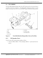
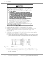
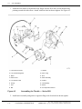
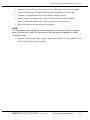
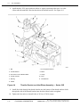
4
KNOCK
Section
Page
4.1
INTRODUCTION ......................................................................................
4-3
4.2
VEHICLE CONDITION .............................................................................
4-4
4.3
KNOCK INTENSITY ................................................................................
4-7
4.4
VERIFICATION OF ENGINE KNOCK ......................................................
4-8
4.5
AIR INTAKE COMPONENTS ...................................................................
4-9
4.6
PSV ASSEMBLY ......................................................................................
4-11
4.7
OXYGEN SENSOR ..................................................................................
4-20
4.8
IGNITION SYSTEM .................................................................................
4-22
4.9
FUEL SYSTEM LEARN PROCEDURE ...................................................
4-28
4.10
ACCESSORIES AND BRACKETS ..........................................................
4-29
4.11
VALVE AND INJECTOR OPERATING MECHANISMS ............................
4-30
4.12
FUEL COMPOSITION .............................................................................
4-31
4.13
INTERNAL ENGINE COMPONENTS ......................................................
4-33
4.14
FAKE KNOCK CODES .............................................................................
4-34
(Rev. 10/03)
4-2
From Bulletin 4-50G/60GTS-03
All information subject to change without notice.
6SE482 0109 Copyright © 2003 DETROIT DIESEL CORPORATION
SERIES 50G/60G TROUBLESHOOTING MANUAL
4.1
INTRODUCTION
The following section gives procedures to diagnose a natural gas Series 50G or Series 60G
DDEC Engine which knocks during operation.
All information subject to change without notice.
(Rev. 10/03)
6SE482 0109 Copyright © 2003 DETROIT DIESEL CORPORATION
From Bulletin 4-50G/60GTS-03
4-3
4.2
VEHICLE CONDITION
4.2
VEHICLE CONDITION
Obvious part and component problems may cause a Knock condition. The first step in diagnosing
the engine is to check related vehicle conditions.
4.2.1
Troubleshooting the Vehicle
To ensure obvious part and component problems are not causing a Knock condition, troubleshoot
as follows:
1. Check the vehicle controls.
[a]
Confirm the vehicle has natural gas in its tanks.
[b]
Confirm the ignition system is on.
[c]
Confirm the batteries are charged.
[d]
Confirm the manual gas valve is open during cranking.
[e]
Confirm the fuel door is closed.
To avoid injury from an explosion of natural gas, the
following precautions must be taken:
Do not smoke when installing or servicing the engine
or fuel system.
Installation or servicing of natural-gas equipment
must only be conducted in well-ventilated, natural gas
compatible areas. Do not install or service equipment
in an enclosed area where ignition sources are present
without first ensuring that an undetected gas leak may
be safely vented without being ignited.
Bleed natural gas lines before installing or servicing
any component connected to the fuel lines.
Natural gas fuel systems are pressurized. Relieve
pressure from any fuel system component prior to
installation or service of that component.
Natural gas is highly flammable and explosive and may be
extremely cold (-260 F [-162 C]).
[f]
If the engine still knocks, go to step 2.
[g]
If the engine no longer knocks, troubleshooting is done.
2. Check electrical connections and electronic controls.
[a]
Confirm wiring harnesses at DDEC® are connected.
[b]
Confirm ground straps from engine to starter are connected.
(Rev. 10/03)
4-4
From Bulletin 4-50G/60GTS-03
All information subject to change without notice.
6SE482 0109 Copyright © 2003 DETROIT DIESEL CORPORATION
SERIES 50G/60G TROUBLESHOOTING MANUAL
[c]
Confirm the PLC/Multiplex/Electrical System is getting power.
[d]
Confirm proper operation of the fire suppression system and the methane detection
system. Refer to OEM Vehicle Manual.
[e]
Confirm proper operation of the fuel door magnetic switch. Refer to OEM Vehicle
Manual.
[f]
Confirm proper operation of all tank valves and high pressure solenoid valve during
cranking. Refer to OEM Vehicle Manual.
[g]
Confirm proper operation of the Stop Engine Light (SEL).
[h]
Confirm proper operation of the Check Engine Light (CEL).
To avoid injury from an explosion of natural gas, the
following precautions must be taken:
Do not smoke when installing or servicing the engine
or fuel system.
Installation or servicing of natural-gas equipment
must only be conducted in well-ventilated, natural gas
compatible areas. Do not install or service equipment
in an enclosed area where ignition sources are present
without first ensuring that an undetected gas leak may
be safely vented without being ignited.
Bleed natural gas lines before installing or servicing
any component connected to the fuel lines.
Natural gas fuel systems are pressurized. Relieve
pressure from any fuel system component prior to
installation or service of that component.
Natural gas is highly flammable and explosive and may be
extremely cold (-260 F [-162 C]).
[i]
If the engine still knocks, go to step 3.
[j]
If the engine no longer knocks, troubleshooting is done.
3. Check the installation requirements for the electronic system.
[a]
Verify the installation requirements for the electronic system have been met.
Refer to section 8. If the engine installation requirements for the electronic system
did not comply, repair as required.
All information subject to change without notice.
(Rev. 10/03)
6SE482 0109 Copyright © 2003 DETROIT DIESEL CORPORATION
From Bulletin 4-50G/60GTS-03
4-5
4.2
VEHICLE CONDITION
To avoid injury from an explosion of natural gas, the
following precautions must be taken:
Do not smoke when installing or servicing the engine
or fuel system.
Installation or servicing of natural-gas equipment
must only be conducted in well-ventilated, natural gas
compatible areas. Do not install or service equipment
in an enclosed area where ignition sources are present
without first ensuring that an undetected gas leak may
be safely vented without being ignited.
Bleed natural gas lines before installing or servicing
any component connected to the fuel lines.
Natural gas fuel systems are pressurized. Relieve
pressure from any fuel system component prior to
installation or service of that component.
Natural gas is highly flammable and explosive and may be
extremely cold (-260 F [-162 C]).
[b]
If the engine still knocks, check the knock intensity refer to section 4.3.
[c]
If the engine no longer knocks, troubleshooting is done.
(Rev. 10/03)
4-6
From Bulletin 4-50G/60GTS-03
All information subject to change without notice.
6SE482 0109 Copyright © 2003 DETROIT DIESEL CORPORATION
SERIES 50G/60G TROUBLESHOOTING MANUAL
4.3
KNOCK INTENSITY
Determine the intensity and frequency of the knock condition as follows:
1. Turn on the ignition. Plug the Diagnostic Data Reader (DDR) or the Diesel Diagnostic
Data Link (DDDL), J 47500, into the Diagnostic Connector.
NOTE:
Use the Pro-Link kit J 38500-H to connect the DDR. Use PC card J 38500-2300 installed
in the computer to connect the DDDL, J 47500.
2. Read active and inactive codes by selecting the DIAGNOSTIC CODE MENU (ACTIVE
CODES) on the DDR or DDDL, J 47500.
3. Determine if the vehicle has Engine Knock Level Above Normal Range (SID 76, FMI 0)
or Engine Knock Level Torque Reduction (SID 76, FMI 7).
[a]
If the number of "Engine Knock Level Above Normal Range" (SID 76, FMI 0)
and "Engine Knock Level Torque Reduction" (SID 76, FMI 7) codes is greater
than or equal to four codes per engine operating hour from the first knock code
occurrence to the last knock code occurrence, verify the knock condition is real.
Refer to section 4.4.
[b]
If the number of "Engine Knock Level Above Normal Range" (SID 76, FMI 0) and
"Engine Knock Level Torque Reduction" (SID 76, FMI 7) codes is less than four
codes per engine operating hour from the first knock code occurrence to the last
knock code occurrence, then clear the codes, put the vehicle back in service, check
vehicle again in 24 hours, refer to step 1 and step 2.
4. If the engine no longer knocks, troubleshooting is done.
All information subject to change without notice.
(Rev. 10/03)
6SE482 0109 Copyright © 2003 DETROIT DIESEL CORPORATION
From Bulletin 4-50G/60GTS-03
4-7
4.4
VERIFICATION OF ENGINE KNOCK
4.4
VERIFICATION OF ENGINE KNOCK
Verify the engine knock codes are actual (real) or externally induced (fake) as follows:
1. Turn the ignition off.
2. Unscrew the Knock Sensor from the block.
3. Hang the Knock Sensor in the engine compartment.
4. Cut a 16 or 18-gage insulated copper wire 30 mm (12 in.) long. Cut the rubber sheath
off both ends to expose 5 mm (2 in.) of the copper leads.
5. Wrap one end of the wire around the threads of the Knock Sensor (secure with electrical
tape) and bolt the other end of the wire to a clean ground on the block.
6. Road test the vehicle.
7. Turn on the ignition. Plug the Diagnostic Data Reader (DDR) or the Diesel Diagnostic
Data Link (DDDL), J 47500, into the Diagnostic Connector.
NOTE:
Use the Pro-Link kit J 38500-H to connect the DDR. Use PC card J 38500-2300 installed
in the computer to connect the DDDL J 47500.
8. Read active and inactive codes by selecting the DIAGNOSTIC CODE MENU (ACTIVE
CODES) on the DDR or DDDL J 47500.
9. If the vehicle registers no knock codes, then the original knock codes are real. Check the
Air Intake Components, refer to section 4.5.
10. If the vehicle still has knock codes then the original knock codes are fake and are being
caused by wiring or bad grounds. Check the starter and block ground connections,
refer to section 4.14.
(Rev. 10/03)
4-8
From Bulletin 4-50G/60GTS-03
All information subject to change without notice.
6SE482 0109 Copyright © 2003 DETROIT DIESEL CORPORATION
SERIES 50G/60G TROUBLESHOOTING MANUAL
4.5
AIR INTAKE COMPONENTS
Check the intake manifold temperature and operation of the Charge Air Cooler, Engine Cooling
Fan, and Air Cleaner as follows:
1. Road test the vehicle.
2. Turn on the ignition. Plug the Diagnostic Data Reader (DDR) or the Diesel Diagnostic
Data Link (DDDL) J 47500 into the Diagnostic Connector.
NOTE:
Use the Pro-Link kit J 38500-H to connect the DDR. Use PC card J 38500-2300 installed
in the computer to connect the DDDL J 47500.
3. Read active and inactive codes by selecting the DIAGNOSTIC CODE MENU (ACTIVE
CODES) on the DDR or DDDL J 47500.
4. With the vehicle is running, use the DDR or DDDL to read the Intake Manifold
Temperature.
[a]
If the Intake Manifold Temperature is below 150 F (66 C), check the Fuel System
Operation. Refer to section 4.6.1.
[b]
If the Intake Manifold Temperature is 150 F (66 C) or higher, check the Charge Air
Cooler. Refer to step 5.
5. Check the operation of the Charge Air Cooler as follows:
[a]
Inspect and pressure check the Charge Air Cooler system. Refer to Series 60 Service
Manual 6SE483 or Series 50 Service Manual 6SE50.
[b]
If the Charge Air Cooler and plumbing are damaged or clogged, replace them. Refer
to the vehicle OEM service manual.
[c]
Road test the vehicle.
[d]
If the engine still knocks, go to step 6.
[e]
If the engine no longer knocks, troubleshooting is done.
6. Check the operation of the Engine Cooling Fan as follows:
[a]
Inspect Engine Cooling Fan. Refer to Series 60 Service Manual 6SE483 or Series 50
Service Manual 6SE50.
[b]
If the Engine Cooling Fan is damage, repair or replace it as required. Refer to Series
60 Service Manual 6SE483 or Series 50 Service Manual 6SE50.
[c]
Road test the vehicle.
[d]
If the engine still knocks, go to step 7.
[e]
If the engine no longer knocks, troubleshooting is done.
7. Check the operation of the Air Cleaner as follows:
[a]
Inspect engine Air Cleaner. Refer to Series 60 Service Manual 6SE483 or Series 50
Service Manual 6SE50.
All information subject to change without notice.
(Rev. 10/03)
6SE482 0109 Copyright © 2003 DETROIT DIESEL CORPORATION
From Bulletin 4-50G/60GTS-03
4-9
4.5
AIR INTAKE COMPONENTS
[b]
Clean or replace the Air Cleaner as required. Refer to the vehicle OEM service
manual.
[c]
Road test the vehicle.
[d]
If the engine still knocks, check the PSV operation. Refer to section 4.6.
[e]
If the engine no longer knocks, troubleshooting is done.
(Rev. 10/03)
4-10
From Bulletin 4-50G/60GTS-03
All information subject to change without notice.
6SE482 0109 Copyright © 2003 DETROIT DIESEL CORPORATION
SERIES 50G/60G TROUBLESHOOTING MANUAL
4.6
PSV ASSEMBLY
The Pulse Width Modulated Stepper Motor Valve (PSV) biases gas flow to the venturi mixer to
control the air fuel ratio. See Figure 4-1. The following PSV component procedures are used to
diagnose a natural gas Series 50G or Series 60G DDEC Engine which knocks during operation.
1. PSV
5. Fuel Mixer
2. Bolt
6. Connector O-rings
3. Washer
7. Fuel Transfer Tube
4. PSV O-ring
Figure 4-1
4.6.1
Pulse Width Modulated Stepper Motor Valve and Fuel Mixer
PSV Operation Check
Check for proper PSV operation during cranking as follows:
1. Connect the DDR or DDDL, J 47500, and display PWM No. 3 position and Gas Valve
position.
All information subject to change without notice.
(Rev. 10/03)
6SE482 0109 Copyright © 2003 DETROIT DIESEL CORPORATION
From Bulletin 4-50G/60GTS-03
4-11
4.6
PSV ASSEMBLY
To avoid injury from an explosion of natural gas, the
following precautions must be taken:
Do not smoke when installing or servicing the engine
or fuel system.
Installation or servicing of natural-gas equipment
must only be conducted in well-ventilated, natural gas
compatible areas. Do not install or service equipment
in an enclosed area where ignition sources are present
without first ensuring that an undetected gas leak may
be safely vented without being ignited.
Bleed natural gas lines before installing or servicing
any component connected to the fuel lines.
Natural gas fuel systems are pressurized. Relieve
pressure from any fuel system component prior to
installation or service of that component.
Natural gas is highly flammable and explosive and may be
extremely cold (-260 F [-162 C]).
2. Crank the engine and read PWM No. 3 position and Gas Valve position.
3. If PWM No. 3 position indicates 26–50 % and Gas Valve position indicates 50–80
% but the engine still knocks, then check the operation of the Oxygen Sensor.
Refer to section 4.7.
4. If PWM No. 3 position indicates 26–50 % and Gas Valve position is not moving, then
check the PSV power and PWM No. 3 output as follows:
[a]
Measure the voltage at the PSV connector (see Figure 4-2) with a voltmeter. Connect
positive lead to wire 446 (red, pin A) and negative lead to wire 150A (black, pin B).
Figure 4-2
[b]
PSV Connector
If there is no voltage, check the Engine Sensor Harness (ESH) and PSV connector.
Refer to DDEC III/IV Single ECM Troubleshooting Guide 6SE497. Repair or replace
the ESH as necessary.
(Rev. 10/03)
4-12
From Bulletin 4-50G/60GTS-03
All information subject to change without notice.
6SE482 0109 Copyright © 2003 DETROIT DIESEL CORPORATION
SERIES 50G/60G TROUBLESHOOTING MANUAL
[c]
If there is a voltage, check the PWM No. 3 output. Connect the voltmeter positive
lead to wire 910 (orange, pin H) and negative lead to wire 150A (black, pin B) in
PSV connector, see Figure 4-2. With the DDR, slew the PWM No. 3 output from
10 % to 50 % and then to 90 %.
[d]
If there is a change in voltage, then troubleshoot the PSV assembly,
refer to section 4.6.2.
[e]
If there is no change in voltage, then troubleshoot the ESH and PSV connector. Refer
to DDEC III/IV Single ECM Troubleshooting Guide 6SE497. Repair or replace
the ESH as necessary.
5. If the gas valve does not move from 0 %, check the voltage using a voltmeter. Connect
positive lead to wire 446 (red, pin A) and negative lead to wire 150A (black, pin B) of the
PSV connector, see Figure 4-2.
[a]
If there is a voltage at the PSV connector, then troubleshoot the PSV assembly,
refer to section 4.6.2.
[b]
If there is no voltage, then troubleshoot the ESH, PSV connector, and the OEM
power harness. Refer to DDEC III/IV Single ECM Troubleshooting Guide 6SE497.
Repair or replace the ESH and the OEM power harness as necessary.
6. If the Gas Valve position moves but appears to have sluggish or erratic movement, check
voltage at the PSV connector with a voltmeter. Connect positive lead to wire 446 (red, pin
A) and negative lead to wire 150A (black, pin B), see Figure 4-2.
4.6.2
[a]
If there is less than 10 volts, charge the batteries.
[b]
If 10-12 volts are present during cranking, then troubleshoot the PSV assembly,
refer to section 4.6.2.
PSV Assembly Troubleshooting
Troubleshoot the PSV assembly as follows:
1. Remove PSV from engine. Do not unplug electronic connector.
2. Remove 13 mm plug and install digital dial indicator (Mitutoyo® Digimatic Indicator,
part No. 575-123 or equivalent).
Mitutoyo® is a registered trademark of Mitutoyo Manufacturing Co., LTD.
3. Plug in DDR reader and go to activate outputs. Input 0 % PWM to PWM No. 3.
4. Set digital indicator to 0 mm (0 in.).
All information subject to change without notice.
(Rev. 10/03)
6SE482 0109 Copyright © 2003 DETROIT DIESEL CORPORATION
From Bulletin 4-50G/60GTS-03
4-13
4.6
PSV ASSEMBLY
5. Input values listed in Table 4-1 from column 1 to PWM No. 3 with the DDR.
PWM No. 3 Reading
Programmed Travel
Travel Limits
0 %
0 mm (0 in.)
10 %
1 mm (0.04 in.)
0.9–1.1 mm (0.035–0.043 in.)
50 %
5 mm (0.20 in.)
4.9–5.1 mm (0.193–0.201 in.)
100 %
10 mm (0.39 in.)
9.9–10.1 mm (0.390–0.398 in.)
Column 2 shows the programmed travel and column 3 shows the limits of acceptable travel.
Table 4-1
PWM No. 3 Input and Acceptable Travel
6. If the PSV assembly shows any of the following failure modes, then replace the
PSV assembly (refer to section 4.6.3), and perform the Fuel System Learn Procedure
(refer to section 4.9).
[a]
PSV remains at or below approximately 50% of travel.
[b]
PSV piston does not move (indicator reads zero throughout).
[c]
PSV moves slowly or does not move to the value listed in Table 4-1, Column 3.
[d]
PSV exhibits erratic operation.
7. If engine no longer knocks, troubleshooting is complete.
8. If engine knocks, check the Ignition System. Refer to section 4.8.
4.6.3
Replacing the Throttle
Use the bolt loosening and tightening sequences and the throttle assembly procedure in the
following sections when replacing the throttle. Refer to section 4.6.3.1 for the bolt loosening and
tightening sequences and refer to section 4.6.3.2 for the throttle assembly procedure.
4.6.3.1
Bolt Tightening Sequence
Loosen the bolts using the following sequence.
1. Loosen the four bolts that attach the intake elbow to the rear of the throttle.
2. Loosen the four bolts that attach the Mixer/PSV assembly to the front of the throttle.
3. Loosen the two bolts that attach the low pressure regulator to the intake elbow.
4. Loosen the four bolts that attach the throttle to the throttle bracket.
Tighten all the bolts using the following sequence:
NOTE:
Torque for all bolts is 34 N·m (25 ft·lb).
1. Tighten the two bolts from the throttle bracket to the gear case.
(Rev. 10/03)
4-14
From Bulletin 4-50G/60GTS-03
All information subject to change without notice.
6SE482 0109 Copyright © 2003 DETROIT DIESEL CORPORATION
SERIES 50G/60G TROUBLESHOOTING MANUAL
2. Tighten the one bolt from the throttle bracket to the cylinder head.
3. Tighten the four bolts from the Mixer/PSV assembly to the throttle.
4. Tighten the four bolts from the throttle to the inlet elbow.
5. Tighten the two bolts from the low pressure regulator.
6. Tighten the two bolts from the throttle bracket to the inlet elbow.
7. Tighten the four bolts from the bottom of the throttle bracket to the throttle.
4.6.3.2
Throttle Assembly Procedure
Replace the throttle assembly as follows:
All information subject to change without notice.
(Rev. 10/03)
6SE482 0109 Copyright © 2003 DETROIT DIESEL CORPORATION
From Bulletin 4-50G/60GTS-03
4-15
4.6
PSV ASSEMBLY
1. Install the inlet elbow to the throttle body flange with the flow arrow on the throttle body
pointing towards the inlet elbow. Attach with four bolts but do not tighten. See Figure 4-3.
1. Fuel Pressure Sensor
9. Washer
2. Low Pressure Regulator
10. PSV O-ring
3. Elbow
11. Bolt
4. Balance Line
12. Mixer Assembly
5. Fuel Transfer Tube
13. Gasket
6. O-rings
14. Throttle Body
7. PSV
15. Elbow
8. Bolt
16. Air Temperature Sensor
Figure 4-3
Assembling the Throttle — Series 50G
2. Install mixer assembly and gasket to opposite flange with four bolts but do not tighten.
(Rev. 10/03)
4-16
From Bulletin 4-50G/60GTS-03
All information subject to change without notice.
6SE482 0109 Copyright © 2003 DETROIT DIESEL CORPORATION
SERIES 50G/60G TROUBLESHOOTING MANUAL
3. Attach the PSV and O-ring to the mixer with four Allen head screws but do not tighten.
4. Lubricate O-rings used with fuel transfer tube with Lubriplate® prior to assembly.
Lubriplate® is a registered trademark of Fiske Brothers Refining Company.
5. Install O-rings to fuel transfer tube. Apply Teflon® liquid pipe sealant to threads.
Teflon® is a registered trademark of E.I. DuPont de Nemours and Company, Inc.
6. Thread fuel transfer tube into regulator and tighten.
NOTE:
The fuel transfer tube must thread into the regulator just far enough so the O-ring seal
does not bottom out in the PSV valve and cut the seal when the regulator is bolted
to the inlet elbow.
7. Install the low pressure regulator and fuel transfer tube into the PSV. Bolt regulator to inlet
elbow with two bolts but do not tighten.
All information subject to change without notice.
(Rev. 10/03)
6SE482 0109 Copyright © 2003 DETROIT DIESEL CORPORATION
From Bulletin 4-50G/60GTS-03
4-17
4.6
PSV ASSEMBLY
8. Install throttle, PSV, mixer and inlet elbow to engine positioning inlet hose over inlet
elbow and inlet manifold. Rest the throttle on the throttle bracket. See Figure 4-4.
1. Bolt
7. Air Temperature Sensor
2. Throttle Bracket
8. Elbow
3. Gear Case Cover-to-Bracket Bolts
9. Clamp
4. Throttle Actuator
10. Hose
5. Bushing
11. Inlet Manifold
6. Gasket
Figure 4-4
Throttle, Bracket, and Inlet Elbow Assembly — Series 50G
9. Install four bolts through the throttle bracket into the bottom of the throttle and two bolts
through the side of the throttle bracket into the inlet elbow but do not tighten.
10. Tighten the four mixer to throttle bolts at 34 N·m (25 ft·lb) torque.
(Rev. 10/03)
4-18
From Bulletin 4-50G/60GTS-03
All information subject to change without notice.
6SE482 0109 Copyright © 2003 DETROIT DIESEL CORPORATION
SERIES 50G/60G TROUBLESHOOTING MANUAL
11. Tighten the four throttle to inlet elbow bolts at 34 N·m (25 ft·lb) torque.
12. Tighten the two bolts that hold the regulator to the inlet elbow and tighten the four screws
that hold the PSV to the mixer.
13. Adjust the two bolts through the throttle bracket to the inlet elbow and the four bolts
through the bottom of the throttle bracket to the throttle alternatively to ensure that there is
no bind in the throttle. Torque the two brackets to the inlet elbow bolts at 34 N·m (25 ft·lb)
and the four throttle mounting bolts at 34 N·m (25 ft·lb).
All information subject to change without notice.
(Rev. 10/03)
6SE482 0109 Copyright © 2003 DETROIT DIESEL CORPORATION
From Bulletin 4-50G/60GTS-03
4-19
4.7
OXYGEN SENSOR
4.7
OXYGEN SENSOR
The oxygen sensor measures exhaust oxygen which is an indication of the air/fuel ratio
(see Figure 4-5). The air/fuel ratio is a fundamental parameter for a natural gas engine. Precise
control of the air/fuel ratio allows the engine to operate closer to the lean limit. As a result,
exhaust emissions, fuel consumption, and exhaust temperatures are reduced.
Figure 4-5
Oxygen Sensor
If fuel system hardware, fuel quality, or engine operating conditions change, DDEC will sense
this and make corrections to keep the air/fuel ratio on target. This is called “closed loop” control.
The oxygen sensor must be installed in the exhaust pipe within 305 mm (12 in.) of the turbine
outlet. The sensor has pre-applied anti-seize on the threads. The oxygen sensor harness must be
used to connect the sensor to the oxygen sensor interface module located at the rear of the engine.
The wires must be routed away from the exhaust system and kept out of contact with moving parts.
Check the Oxygen Sensor for proper operation as follows:
1. Place the diagnostic oxygen sensor (Engine Control & Monitoring Inc. diagnostic oxygen
sensor, Lambda PRO™ kit or equivalent, in the secondary port in the exhaust tube.
Lambda Pro trademark is owned by ECM Engine Control and Monitoring.
2. Connect the DDR or DDDL, J 47500, and display air/fuel ratio Lambda value.
NOTE:
Use the Pro-Link kit J 38500-H to connect the DDR. Use PC card J 38500-2300 installed
in the computer to connect the DDDL, J 47500.
(Rev. 10/03)
4-20
From Bulletin 4-50G/60GTS-03
All information subject to change without notice.
6SE482 0109 Copyright © 2003 DETROIT DIESEL CORPORATION
SERIES 50G/60G TROUBLESHOOTING MANUAL
NOTICE:
Use care not to overheat the transmission during the stall torque
test. Overheating the transmission will cause damage.
3. Perform a transmission stall torque test.
[a]
Run the stall for approximately 10 seconds.
NOTE:
Engine and transmission should be at normal operating temperatures.
[b]
Record the air/fuel ratio Lambda value displayed by DDEC and the diagnostic
oxygen sensor.
4. Waiting one minute between tests, repeat step 3 twice.
[a]
If the readings between the diagnostic oxygen sensor and DDEC oxygen sensor
are constantly more than +/- 0.02 Lambda different, replace the Oxygen Sensor
(see Figure 4-5) and then perform the Learn Procedure. Refer to section 4.9.
[b]
If the readings between the diagnostic oxygen sensor and DDEC oxygen sensor
are generally less than or equal to +/- 0.02 Lambda or less but fluctuate to +/-0.04
Lambda or higher, replace the Low Pressure Regulator, refer to section 4.6.3.
[c]
If the readings between the diagnostic oxygen sensor and the DDEC oxygen sensor
are always +/- 0.02 Lambda or less and the engine still knocks, then check the
condition of the spark plug (refer to section 4.8).
5. If the engine operates normally, troubleshooting is done.
All information subject to change without notice.
(Rev. 10/03)
6SE482 0109 Copyright © 2003 DETROIT DIESEL CORPORATION
From Bulletin 4-50G/60GTS-03
4-21
4.8
4.8
IGNITION SYSTEM
IGNITION SYSTEM
The Ignition System's main components are the ignition coil harness, the igniter module, the
ignition coils, the ignition boot assemblies, the spark plugs, and the ground strap, see Figure 4-6.
In addition, the Ignition System requires a different rocker cover with extension tubes for the
spark plugs attached to the rocker cover cap, see Figure 4-7. Also, the cylinder head is machined
to accept the spark plug extension tubes.
1. Boot and Spring Assembly
6. Ignition Coil Harness
2. Ignition Coil Assembly
7. Spark Plug
3. Igniter Module Bracket
8. O-ring
4. Bolt
9. Ignition Coil and Boot Assembly
10. Ground Strap
5. Igniter Module
Figure 4-6
Ignition System — Series 50G
(Rev. 10/03)
4-22
From Bulletin 4-50G/60GTS-03
All information subject to change without notice.
6SE482 0109 Copyright © 2003 DETROIT DIESEL CORPORATION
SERIES 50G/60G TROUBLESHOOTING MANUAL
1. Gasket
8. Rocker Cover Cap
2. O-ring
9. Bolt
3. Extension Tube
10. Isolator
4. O-ring
11. Spacer
5. Screw
12. Rocker Cover Base
6. Cover
13. Seal Ring
7. Bolt
Figure 4-7
Two-Piece Rocker Cover — Series 50G
The following procedures are used to diagnose a natural gas Series 50G or Series 60G DDEC
Engine which knocks during operation.
4.8.1
Spark Plug Well Inspection
Check the Spark Plug Wells as follows:
All information subject to change without notice.
(Rev. 10/03)
6SE482 0109 Copyright © 2003 DETROIT DIESEL CORPORATION
From Bulletin 4-50G/60GTS-03
4-23
4.8
IGNITION SYSTEM
1. Remove the coil cover.
2. Disconnect each coil.
3. Examine each ignition boot, spark plug, and spark plug well.
4. If oil is present on any ignition boot or in the spark plug well, replace the O-rings on
the extension tube; replace the ignition boot; and clean and reinstall the ignition coils.
Perform the Fuel System Learn Procedure, refer to section 4.9.
5. If water is present in any spark plug well, clean out the well and discard the defective
spark plug and replace the mating boot and spring assembly. Gap spark plug to 0.38 mm
(0.015 in.). Install the spark plug. Tighten the spark plug to 38 N·m (28 ft·lb). Perform the
Fuel System Learn Procedure, refer to section 4.9.
6. If ignition coils, boots, and spark plug wells are free of oil or other contamination, check
the Spark Plug Electrode, refer to section 4.8.2.
4.8.2
Spark Plug Electrode Inspection
Check the Spark Plug Electrodes as follows:
1. Remove each spark plug.
2. Examine the spark plug electrodes for the following conditions:
[a]
If any spark plug is shorted by excessive oil deposits around center and ground
electrodes (see Figure 4-8), replace the spark plug and go to step 3.
Thick, wet, and black deposits around bottom of spark plug.
Figure 4-8
Spark Plug with Oil-Fouled Electrode
(Rev. 10/03)
4-24
From Bulletin 4-50G/60GTS-03
All information subject to change without notice.
6SE482 0109 Copyright © 2003 DETROIT DIESEL CORPORATION
SERIES 50G/60G TROUBLESHOOTING MANUAL
[b]
If any spark plug is shorted by carbon deposits (see Figure 4-9), replace the spark
plug and go to step 3.
Soft, sooty, dry, and black deposits around bottom of spark plug.
Figure 4-9
Carbon-Fouled Spark Plug
All information subject to change without notice.
(Rev. 10/03)
6SE482 0109 Copyright © 2003 DETROIT DIESEL CORPORATION
From Bulletin 4-50G/60GTS-03
4-25
4.8
IGNITION SYSTEM
[c]
If any spark plug is shorted across the gap (see Figure 4-10) by reforming of melted
material from the electrodes, go to step 3.
There is melting of electrode material in the gap.
Figure 4-10
Spark Plug with Gap Bridging
(Rev. 10/03)
4-26
From Bulletin 4-50G/60GTS-03
All information subject to change without notice.
6SE482 0109 Copyright © 2003 DETROIT DIESEL CORPORATION
SERIES 50G/60G TROUBLESHOOTING MANUAL
[d]
If the spark plug shows normal operating conditions (see Figure 4-11) with no
deposits or only light tan or gray deposits, reuse the spark plug. Clean the spark plug
and spark plug well. Gap spark plug to 0.38 mm (0.015 in.). Install and tighten
the spark plug to 38 N·m (28 ft·lb). .
Light brown, gray, or tan deposits are acceptable.
Figure 4-11
Normal Operating Spark Plug
3. Gap spark plugs to 0.38 mm (0.015 in.). Tighten the spark plugs to 38 N·m (28 ft·lb).
Check the Accessories and Brackets, refer to section 4.10.
All information subject to change without notice.
(Rev. 10/03)
6SE482 0109 Copyright © 2003 DETROIT DIESEL CORPORATION
From Bulletin 4-50G/60GTS-03
4-27
4.9
FUEL SYSTEM LEARN PROCEDURE
4.9
FUEL SYSTEM LEARN PROCEDURE
Fill in the AFR table for the Fuel System as follows:
NOTE:
Use a chassis dynamometer to apply loads to the engine whenever appropriate as an
alternative to on-highway vehicle operation.
1. Fill in the AFR table values from idle to No Load speed for the unloaded portion as
follows:
[a]
Reset the AFR table with the DDR.
[b]
Slowly increase the engine speed from idle to No Load (0–100 % throttle) and then
slowly decrease the speed back to idle (100–0 % throttle) over one minute.
[c]
Repeat step 1[b] two times.
2. Fill in the AFR table values from idle to Stall speed for the loaded portion as follows:
[a]
With an applied load, slowly increase the engine speed from idle to Stall speed
(0–100 % throttle) and then slowly decrease the speed back to idle (100–0 % throttle)
over one minute.
[b]
Repeat step 2[a] two times.
3. Fill in the AFR table above the Stall speed for the unloaded portion as follows:
NOTE:
The engine must operate in this speed/boost range for a moderate length of time. The
AFR table will not completely fill in just passing through this range.
NOTE:
The best method to apply a load through Stall speed to 2100 RPM is to drive the vehicle
up a hill, locked into a lower gear to prevent transmission shifting. If a hill is not available,
lock the vehicle in low gear and accelerate from a stop to 2100 RPM full load.
[a]
Slowly operate the engine from Stall speed to 2100 RPM with an applied load.
[b]
Repeat step 3[a] until the engine runs smooth through this speed range.
4. Road test the vehicle as follows:
[a]
Operate the engine through a variety of speed and loads while looking for any
misfires.
[b]
If a particular RPM/Manifold pressure range still experiences misfire, then operate
the engine around that point by running through that range slowly.
[c]
Repeat step 4[a] and step 4[b] until the engine runs smooth without any lean misfires.
A smooth running engine means the Fuel System Learn Procedure is complete.
(Rev. 10/03)
4-28
From Bulletin 4-50G/60GTS-03
All information subject to change without notice.
6SE482 0109 Copyright © 2003 DETROIT DIESEL CORPORATION
SERIES 50G/60G TROUBLESHOOTING MANUAL
4.10 ACCESSORIES AND BRACKETS
Check all accessories and brackets located on or near the engine as follows:
1. Open engine compartment doors.
2. Start the engine using the controls located at the engine bay.
3. Turn the vehicle air conditioning on.
4. Slowly take the engine from idle to 2100 RPM and back down to idle over a one minute
time period.
5. Observe and inspect the air conditioner, air compressor, generator, hydraulic pumps, fan
clutches, etc. and their associated brackets for excessive vibration or uncommon operation.
[a]
If there is no vibration or uncommon operation, check the Valve and Injector
Operating Mechanisms. Refer to section 4.11.
[b]
If there is excessive vibration or the accessories are not firmly attached, repair and
install the respective accessory properly. Repeat step 4[b] and confirm proper
operation.
6. Connect the DDR or DDDL, J 47500.
NOTE:
Use the Pro-Link kit J 38500-H to connect the DDR. Use PC card J 38500-2300 installed
in the computer to connect the DDDL, J 47500.
7. Check for Knock Codes. If the no Knock Codes are present, troubleshooting is done.
All information subject to change without notice.
(Rev. 10/03)
6SE482 0109 Copyright © 2003 DETROIT DIESEL CORPORATION
From Bulletin 4-50G/60GTS-03
4-29
4.11
VALVE AND INJECTOR OPERATING MECHANISMS
4.11 VALVE AND INJECTOR OPERATING MECHANISMS
Check the Valve and Injector Operating Mechanisms for problems that could cause Knock as
follows:
1. Remove upper portion of the rocker cover assembly. Refer to Series 60 Service Manual
6SE483 or Series 50 Service Manual 6SE50.
NOTE:
For best results, check the Valve and Injector Operating Mechanisms for problems
with engine at room temperature.
2. Ensure the Valve and Injector Operating Mechanisms are in good operating condition.
Refer to Series 60 Service Manual 6SE483 or Series 50 Service Manual 6SE50.
3. Check the valve lash. Ensure the Intake valve lash is set at 0.28 mm (0.011 in.) and
the exhaust valve lash is set at 0.91 mm (0.036 in.). Refer to Series 60 Service Manual
6SE483 or Series 50 Service Manual 6SE50.
NOTE:
Valve Lash must be measured with engine at room temperature.
[a]
If the valves are not set at proper lash values, reset the Intake valves at 0.28 mm
(0.011 in.) and the exhaust valves at 0.91 mm (0.036 in.).
[b]
If the valves are set at the proper lash values, check the Fuel Composition.
Refer to section 4.12.
4. If the no longer knocks, troubleshooting is done.
(Rev. 10/03)
4-30
From Bulletin 4-50G/60GTS-03
All information subject to change without notice.
6SE482 0109 Copyright © 2003 DETROIT DIESEL CORPORATION
SERIES 50G/60G TROUBLESHOOTING MANUAL
4.12 FUEL COMPOSITION
The quality of fuel used is a very important factor in obtaining satisfactory engine performance,
long engine life, and acceptable exhaust emission levels. Listed in Table 4-2 are the DDC fuel
specifications for both CNG and LNG. Regardless of the type of fuel, fuel entering the engine
must meet or exceed DDC's published CNG specifications.
Property
Hydrocarbon
ASTM Test
Method
Limit
Mole Percent
Methane
88% min.
Ethane
6% max.
Propane
1.7% max.
Other: C4 and Higher
0.3% max.
Other Gaseous Species
D 1945
Mole Percent
Hydrogen
0.1% max.
D 2650
Carbon dioxide + Nitrogen + Oxygen
4.5% max.
D 1945
Carbon Monoxide
0.1% max.
D 2650
Methanol
0% mass
No Test Method
Sulfur, Total
22 ppm/v
D4468
Other Species
Performance Related Properties
Motor Octane Number
115 min.
D 2623 *
3
Wobbe Number
1290-1380 BTU/ft
Contaminants
†
Pressure Water Dew Point Temperature, Max.
‡
Pressure Hydrocarbon Dew Point Temperature, Max.
D 3588
D 1142
‡ Below which
will form 1%
condensate
Odorant
* Test method D 2623 was obsoleted by ASTM in 1991. Wobbe Index (WI), also known as Wobbe Number, is a measure of fuel
energy flow rate through a fixed orifice under given inlet conditions. Numerically, WI = (dry, higher heating value)/(specific gravity)
† The compressed natural gas shall not contain dust, sand, dirt, gums, oils, or other substances in an amount sufficient to be
injurious to the fuel station equipment or the vehicle being fueled.
‡ The dew point at vehicle fuel storage container pressure shall be at least 5.6 C (10 F) below the 99.0% winter design temperature
for Climatic Conditions for the United States in the American Society of Heating, Refrigerating and Air conditioning Engineer’s
(ASHRAE) Handbook. Testing for water vapor shall be in accordance with ASTM D 1142, utilizing the Bureau of Mines apparatus.
The natural gas at ambient conditions must have a distinctive odor potent enough for its presence to be detected down to a
concentration in air of 1% by volume.
Table 4-2
Compressed Natural Gas Fuel Specifications
All information subject to change without notice.
(Rev. 10/03)
6SE482 0109 Copyright © 2003 DETROIT DIESEL CORPORATION
From Bulletin 4-50G/60GTS-03
4-31
4.12
FUEL COMPOSITION
Check the Fuel Composition for problems that could cause Knock as follows:
1. Ask for a gas analysis from your local gas supplier and confirm that the gas that you are
using is within DDC's specifications listed in Table 4-2.
[a]
If the fuel is within DDC's specification, then check the Internal Engine Components.
Refer to section 4.13.
[b]
If the fuel is not within DDC's Specifications contact Technical Service.
2. If the no longer knocks, troubleshooting is done.
(Rev. 10/03)
4-32
From Bulletin 4-50G/60GTS-03
All information subject to change without notice.
6SE482 0109 Copyright © 2003 DETROIT DIESEL CORPORATION
SERIES 50G/60G TROUBLESHOOTING MANUAL
4.13 INTERNAL ENGINE COMPONENTS
Check the internal engine components for problems that could cause Knock as follows:
1. Check to see if the engine has been rebuilt.
[a]
If the engine has been rebuilt, make sure that it has the correct Connecting Rods.
NOTE:
The proper connecting rods for a Series 50G and 60G are shorter in length and are
identified by the words “Natural Gas' on their side.
[b]
If the proper connecting rods are installed, proceed to Fake Knock Codes.
Refer to section 4.14.
2. Check the valves (intake and exhaust) for built up combustion deposits.
[a]
If there are no deposits, confirm proper operation of the Valve and Injector Operating
Mechanisms.
[b]
If there are deposits, determine the cause of the excessive deposits. Check valves,
valve guides, seals, and the cylinder kits. Refer to the Series 60 Service Manual
6SE483 or refer to the Series 50 Service Manual 6SE50.
3. If the no longer knocks, troubleshooting is done.
All information subject to change without notice.
(Rev. 10/03)
6SE482 0109 Copyright © 2003 DETROIT DIESEL CORPORATION
From Bulletin 4-50G/60GTS-03
4-33
4.14
FAKE KNOCK CODES
4.14 FAKE KNOCK CODES
Check for poor grounds causing Fake Knock Codes as follows:
1. Confirm the Starter to Block ground is a No. 00 cable.
[a]
If cable wire gage is too small, replace with a larger gage cable.
[b]
If cable wire gage is suitable, go to step 2.
2. Confirm the Starter to Frame ground is a No. 00 cable.
[a]
If cable wire gage is too small, replace with a larger gage cable.
[b]
If cable wire gage is suitable, go to step 3.
3. Check the Starter to Block, Starter to Frame, and SNEF module ground (wire No. 954,
black) to block ground wires as follows:
[a]
Using a digital volt-ohmmeter, measure resistance in each cable. If the resistance is
greater than 50 m , replace the ground wire.
[b]
Examine the points for each cable. If the points have rust, paint and corrosion,
clean the points and reconnect.
[c]
If all the resistances are less than 50 m and the connections are clean, go to step 4.
4. Confirm the ground surfaces are properly connected to the vehicle ground. Repair any bad
ground connection and continue.
5. If the Fake Knock Code problem continues, contact DDC technical service.
6. If there are no longer Knock Codes, troubleshooting is done.
(Rev. 10/03)
4-34
From Bulletin 4-50G/60GTS-03
All information subject to change without notice.
6SE482 0109 Copyright © 2003 DETROIT DIESEL CORPORATION