1
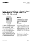
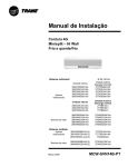
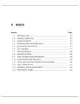
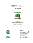
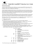
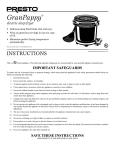
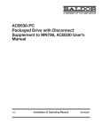
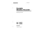
SERIES 50 SERVICE MANUAL
1.29.3
Disassembly of the Accessory Drive
Disassemble the accessory drive as follows:
NOTE:
For disassembly and assembly of the accessory drive use toolset
J 36024-D. See Figure 1-387
NOTE:
Engines built after December 2000, use the following tools for accessory drive seal
removal and installation: J 45533 seal remover, J 45833 seal installer, and J 45877 seal
runout gauge adapter to verify proper installation of seal in accessory drive. These tools
are part of toolset J 36024-D. See Figure 1-387.
All information subject to change without notice.
6SE50 0006 Copyright © 2003 D ETROIT DIESEL CORPORATION
From Bulletin 1-50-03
1-483
1.29
ACCESSORY DRIVE
NOTE:
The seal, pulley and pulley nut are the only serviceable parts of the accessory drive
assembly with the unitized oil seal.
Figure 1-387
Accessory Drive Service Tool Set J 36024-D
All information subject to change without notice.
1-484
From Bulletin 1-50-03
6SE50 0006 Copyright © 2003 DETROIT DIESEL CORPORATION
SERIES 50 SERVICE MANUAL
1. Attach the accessory drive gear to the holding fixture, J 36024-3 part of J 36024-D, using
the three bolts provided. See Figure 1-388.
Figure 1-388
Holding Fixture
All information subject to change without notice.
6SE50 0305 Copyright © 2003 D ETROIT DIESEL CORPORATION
From Bulletin 1-50-03
1-484a
1.29
ACCESSORY DRIVE
This page intentionally left blank.
All information subject to change without notice.
1-484b
From Bulletin 1-50-03
6SE50 0305 Copyright © 2003 DETROIT DIESEL CORPORATION
SERIES 50 SERVICE MANUAL
2. Place the accessory drive assembly holding fixture into a vise. See Figure 1-389.
Figure 1-389
Accessory Drive Pulley Locknut Removal
All information subject to change without notice.
6SE50 0305 Copyright © 2003 D ETROIT DIESEL CORPORATION
From Bulletin 1-50-03
1-485
1.29
ACCESSORY DRIVE
3. Loosen and remove the accessory drive pulley locknut.
4. Remove the accessory drive pulley by tapping it with a rubber hammer or fiber mallet. If
the pulley does not come off easily, use a puller to remove it. See Figure 1-378.
1. Seal Sleeve
Figure 1-378a
J 45533 Accessory Drive Seal Remover
NOTE:
Perform steps 5, 6, and 7 unitzed seal removal procedure, for accessory drive
assemblies on engines built after December 2000.
5. Using J 45533 (part of toolset J 36024-D), remove seal sleeve.
[a]
Ensure taper end of puller bolt is pointed toward inside jaws. See Figure 1-378a.
[b]
Place inside jaws of tool over sleeve. See Figure 1-378a.
[c]
Finger tighten hex bolt on side of tool.
[d]
Remove sleeve by tightening puller bolt.
All information subject to change without notice.
1-486
From Bulletin 1-50-03
6SE50 0006 Copyright © 2003 DETROIT DIESEL CORPORATION
SERIES 50 SERVICE MANUAL
6. Removal of seal.
[a]
Invert puller bolt. See Figure 1-389b
Figure 1-389b
J 45533 Invert Puller Bolt
[b]
Loosen hex bolt on side of tool.
[c]
Using a rubber mallet, gently drive outside jaws between seal and shaft through the
rubber membrane of seal until tool bottoms out.
[d]
Finger tighten hex bolt on side of tool.
[e]
Remove seal by tightening puller bolt.
7. Clean accessory drive housing at seal location.
All information subject to change without notice.
6SE50 0305 Copyright © 2003 D ETROIT DIESEL CORPORATION
From Bulletin 1-50-03
1-486a
1.29
ACCESSORY DRIVE
8. Position the accessory drive assembly on a press bed with the holding fixture supported.
See Figure 1-390.
Figure 1-390
Accessory Drive Gear Removal
9. Using a press, apply pressure through the access hole in the holding fixture,
J 36024-3 part of J 36024-D, and press the driveshaft out of the gear.
All information subject to change without notice.
1-486b
From Bulletin 1-50-03
6SE50 0305 Copyright © 2003 DETROIT DIESEL CORPORATION
SERIES 50 SERVICE MANUAL
10. Remove the snap ring from the accessory drive housing. See Figure 1-391.
Figure 1-391
Snap Ring Removal
11. Turn the housing over and support the accessory drive housing on the machined surface
using Vee-blocks.
12. Using a press, apply pressure to the pulley end of the shaft and remove the shaft and
bearing assembly.
13. Turn the accessory drive housing over, and support it on the attaching bolt bosses using
Vee-blocks.
All information subject to change without notice.
6SE50 0305 Copyright © 2003 D ETROIT DIESEL CORPORATION
From Bulletin 1-50-03
1-487
1.29
ACCESSORY DRIVE
NOTICE:
For assemblies with inner race for needle bearing, place the
accessory driveshaft in a vise with soft jaws taking care not to
damage the shaft surface.
14. Install needle bearing remover and installer, J 36024-2 part of J 36024-D. See Figure 1-392.
Apply pressure to J 36024-2 part of J 36024-D, and remove the needle bearing.
Figure 1-392
Needle Bearing Removal
15. Apply pressure to J 36024-2 part of J 36024–C and remove the needle bearing.
All information subject to change without notice.
1-488
From Bulletin 1-50-03
6SE50 0305 Copyright © 2003 DETROIT DIESEL CORPORATION
SERIES 50 SERVICE MANUAL
16. Remove the snap ring from the accessory driveshaft. See Figure 1-393.
Figure 1-393
Snap Ring Removal
All information subject to change without notice.
6SE50 0305 Copyright © 2003 D ETROIT DIESEL CORPORATION
From Bulletin 1-50-03
1-489
1.29
ACCESSORY DRIVE
17. Position two steel press plates under the ball bearing outer race. See Figure 1-394.
Figure 1-394
Ball Bearing Removal
NOTE:
Whenever the needle or ball bearing is removed from the shaft, they MUST be replaced
with new bearing assemblies.
18. Use a press to apply pressure to the top of the shaft and remove the ball bearing from
the shaft.
1.29.3.1
Inspection of the Accessory Drive
Clean the accessory drive prior to inspection as follows:
1. Clean all of the parts with clean fuel oil.
All information subject to change without notice.
1-490
From Bulletin 1-50-03
6SE50 0305 Copyright © 2003 DETROIT DIESEL CORPORATION