1
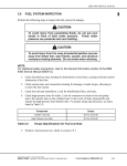
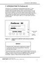
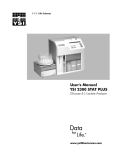
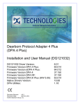
DDEC IV APPLICATION AND INSTALLATION MANUAL
7
TOOLS
Section
Page
7.1
DIAGNOSTIC REQUEST SWITCH ........................................................
7-3
7.2
VEHICLE ELECTRONIC PROGRAMMING SYSTEM ............................
7-5
7.3
DIAGNOSTIC DATA READER ................................................................
7-7
7.4
DETROIT DIESEL DIAGNOSTIC LINK ..................................................
7-27
7.5
DDEC REPROGRAMMING SYSTEM ....................................................
7-29
7.6
DDEC ENGINE PROTECTION SIMULATION KIT ..................................
7-35
7.7
DDEC MANUALS ....................................................................................
7-37
All information subject to change without notice. (Rev. (Rev. 3/02))
7SA742 0203 Copyright © 2002 DETROIT DIESEL CORPORATION
7-1
TOOLS
THIS PAGE INTENTIONALLY LEFT BLANK
7-2
All information subject to change without notice. (Rev. (Rev. 3/02))
7SA742 0203 Copyright © 2002 DETROIT DIESEL CORPORATION
DDEC IV APPLICATION AND INSTALLATION MANUAL
7.1
DIAGNOSTIC REQUEST SWITCH
The Diagnostic Request Switch is used to activate the CEL/SEL lights to flash codes. Active
codes are flashed on the SEL and inactive codes are flashed on the CEL (see see Figure 5-6).
Inactive codes are flashed in numerical order, active codes are flashed in the order received, most
recent to least recent. The Diagnostic Request Switch can be used as the SEO switch also. The
codesare flashed out of the ECM connected to the switch.
Figure 7-1
Flash Codes
NOTE:
For multi-ECM installations, the Diagnostic Request Switch and SEO are combined on
the master ECM. All receiver ECMs have a separate Diagnostic Request Switch.
The Diagnostic Request Switch is used to flash codes in the following circumstances:
The engine is not running and ignition is on
The engine is idling and not in an "engine protection" condition
In both circumstances activating and holding the Diagnostic Request Switch will flash out the
diagnostic codes. For additional information, refer to section 5.5, "Diagnostics."
All information subject to change without notice. (Rev. (Rev. 3/02))
7SA742 0203 Copyright © 2002 DETROIT DIESEL CORPORATION
7-3
TOOLS
THIS PAGE INTENTIONALLY LEFT BLANK
7-4
All information subject to change without notice. (Rev. (Rev. 3/02))
7SA742 0203 Copyright © 2002 DETROIT DIESEL CORPORATION
DDEC IV APPLICATION AND INSTALLATION MANUAL
7.2
VEHICLE ELECTRONIC PROGRAMMING SYSTEM
The purpose of the DDEC Vehicle Electronics Programming System (VEPS) is to give OEMs
the ability to configure many ECM parameters. This allows DDEC features to be tailored to the
specific customer requirements when the vehicle is assembled. Some of the features which
may be configured by VEPS are the transmission type, cruise control, vehicle speed limit, idle
shutdown, rating switches, digital inputs, and digital outputs. VEPS requires the Windows 95
operating system.
7.2.1
SOFTWARE
The VEPS PC software package consists of the several files which are extracted when the
software installation program is executed. A System Users Manual which defines the available
parameters is included with the software package at the time of purchase.
The PC interface utilizes a communications driver which is defined in the TMC Recommended
Practice RP1210A. The RP1210A software is used to translate the datalink signal of the ECM to
the format required by Windows programs. The RP1210A communications driver is included as
part of the VEPS software package.
7.2.2
HARDWARE
The hardware portion of the VEPS programming package includes the interface module and
cables. The components that are included in the package are listed in Table 7-1.
Part Description
Part Number
100 Foot Cable
23512893
SAE J1708 6-Pin Dash Connector
23515957
J1708/RS-232 Translator Box
23512415
6 foot Cable
23515869
Table 7-1
VEPS Hardware
A cable kit, listed in Table 7-2, is also available.
Part Description
Part Number
Cable Kit
(includes the 100 foot cable and the 6-pin dash connector)
23512980
Table 7-2
VEPS Cable Kit
A translator and cable kit, listed in Table 7-3, is also available.
All information subject to change without notice. (Rev. (Rev. 3/02))
7SA742 0203 Copyright © 2002 DETROIT DIESEL CORPORATION
7-5
TOOLS
Part Description
Part Number
Translator Kit
(includes the J1708/RS-232 translator box, 100 foot cable
and the 6-pin dash connector)
23512895
Table 7-3
VEPS Translator and Cable Kit
The VEPS software kit, listed in Table 7-4, is available.
Part Description
Part Number
Software Kit
(includes the RP1202 Software and the VEPS Software)
Contact DDC Application Engineering
Table 7-4
7.2.3
VEPS Software Kit
OPTIONAL PARTS KITS
DDC offers vehicle repower kits to aid in the installation of DDEC III/IV.
NOTE:
This is a repower kit for DDEC II to DDEC III only. There are no repower kits for
NOTE:
DDEC IV.
The kits listed in Table 7-5and Table 7-6 include all of the necessary wiring for the installation of
the DDEC III/IV engine and the following parts:
Table 7-5
Table 7-6
Part Description
Part Number
Terminal Kit
23515326
Vehicle Harness - 30 foot
23515152
Power Harness - 22 foot
23515151
Light and Switch Kit
23501634
DDEC Repower Kit - DDC P/N: 23515327
Part Description
Part Number
Terminal Kit
23515326
Vehicle Harness - 70 foot
23515153
Power Harness - 22 foot
23515151
Light and Switch Kit
23501634
DDEC Repower Kit - DDC P/N: 23515328
The harnesses come with ECM connectors on one end and no connections on the other end.
These harnesses are intended to be cut to length by the OEM. The harnesses come with all the
connections in the ECM connector. Wires can be removed if not used in a specific application.
7-6
All information subject to change without notice. (Rev. (Rev. 3/02))
7SA742 0203 Copyright © 2002 DETROIT DIESEL CORPORATION
DDEC IV APPLICATION AND INSTALLATION MANUAL
7.3
DIAGNOSTIC DATA READER
The hand-held DDR plugs into the Diagnostic Data Link Connector located in the Vehicle
Interface Harness (refer to section 3.10.7). This connection allows the DDR to receive data
from the ECM. The DDR is used to display:
Engine Description via the ENGINE DATA LIST menu
Codes via the DIAGNOSTIC CODES menu
View/reprogram certain operating parameters
A printout of the information displayed on the DDR can be obtained by attaching a printer.
7.3.1
REQUIREMENTS
The components required to receive data from the DDEC system can be seen in the next
illustration (see Figure 7-2). The components and part numbers are listed in Table 7-7.
Component
Part Number
Pro-Link Main Unit
J 38500-1A
Multi Protocol Cartridge (MPC)
J 38500-1500C
Detroit Diesel Application Suite PC Card, DDEC III/IV
J 38500-2300D
Table 7-7
6 pin Deutsch Adapter
J 38500-60A
6 pin to 9 pin Deutsch Adapter
J 38500-96A
Pro-Link Reprogramming Cable
J 38500-925
Pro-Link Portable Printer
J 38480-A
Diagnostic Data Reader Components and Part Numbers
NOTE:
Printers used in Europe must use a European power supply as listed in Table 7-8. Do not
substitute an AC adapter for the European power supply.
Table 7-8
Component
Part Number
Printer (U.S.A.)
J 38480-A
Printer with European Power Supply
J 38699
European Power Supply only
J 38480-220
DDR Printers and Power Supply
All information subject to change without notice. (Rev. (Rev. 3/02))
7SA742 0203 Copyright © 2002 DETROIT DIESEL CORPORATION
7-7
TOOLS
To avoid injury from loss of vehicle/vessel control, the
operator of a DDEC equipped engine must not attempt to use
or read the Diagnostic Data Reader when the vehicle/vessel
is moving.
The DDR must be used by personnel other than the vehicle operator. The vehicle operator must
maintain control of the vehicle while an assistant performs the diagnostic evaluations.
Figure 7-2
Diagnostic Data Reader Kit Plus DDEC Cartridge and PCMCIA Card
The DDR can be purchased from:
7-8
All information subject to change without notice. (Rev. (Rev. 3/02))
7SA742 0203 Copyright © 2002 DETROIT DIESEL CORPORATION
DDEC IV APPLICATION AND INSTALLATION MANUAL
Kent-Moore
28635 Mound Road
Warren, MI 48092
Phone: 1-800-328-6657
See Figure 7-3 for a DDR menu options map.
All information subject to change without notice. (Rev. (Rev. 3/02))
7SA742 0203 Copyright © 2002 DETROIT DIESEL CORPORATION
7-9
TOOLS
Figure 7-3
7-10
DDR Menu Options (Release 24.0 Software)
All information subject to change without notice. (Rev. (Rev. 3/02))
7SA742 0203 Copyright © 2002 DETROIT DIESEL CORPORATION
DDEC IV APPLICATION AND INSTALLATION MANUAL
7.3.2
ENGINE DATA LIST
The DDR can be used to view operational data and parameter settings, via the Engine Data
List feature.
View operational data as follows:
1. Turn the ignition ON.
2. Press
until ENGINE DATA LIST is shown on the screen.
3. Scroll through the data list by pressing
is shown on the screen.
All information subject to change without notice. (Rev. (Rev. 3/02))
7SA742 0203 Copyright © 2002 DETROIT DIESEL CORPORATION
and
until the desired parameter
7-11
TOOLS
7.3.3
DIAGNOSTIC CODES
The DDR can be used to view active and inactive codes.
Active Codes
View the (active) codes as follows:
1. Press
until the SELECT DESIRED MENU appears on the screen.
2. Select ENGINE and press
3. Press
until DIAGNOSTIC CODES is shown on the screen.
4. Then press
5. Press
.
until ACTIVE CODES is shown on the screen.
6. Then press
7. Press
.
to view the first active code.
and
to scroll through the active codes.
NOTE:
Refer to Appendix A for a list of all DDEC codes and code descriptions.
7-12
All information subject to change without notice. (Rev. (Rev. 3/02))
7SA742 0203 Copyright © 2002 DETROIT DIESEL CORPORATION
DDEC IV APPLICATION AND INSTALLATION MANUAL
Inactive Codes
View the inactive codes as follows:
1. Press
until the SELECT DESIRED MENU appears on the screen.
2. Select ENGINE and press
3. Press
until DIAGNOSTIC CODES is shown on the screen.
4. Then press
5. Press
.
until INACTIVE CODES is shown on the screen.
to view the first inactive code.
6. Then press
7. Press
.
and
to scroll through the inactive codes.
NOTE:
Refer to Appendix A for a list of all DDEC codes and code descriptions.
All information subject to change without notice. (Rev. (Rev. 3/02))
7SA742 0203 Copyright © 2002 DETROIT DIESEL CORPORATION
7-13
TOOLS
Clearing Codes With A DDR
The diagnostic codes stored in the ECM's memory can be cleared with a DDR, via the
DIAGNOSTIC CODES menu. To clear the codes perform the following:
1. Press
until the SELECT DESIRED MENU appears on the screen.
2. Select ENGINE and press
3. Press
4. Then press
5. Press
.
until DIAGNOSTIC CODES is shown on the screen.
.
until CLEAR CODES is shown on the screen.
.
6. Then
press
7. Use
7-14
to select YES to clear the codes.
All information subject to change without notice. (Rev. (Rev. 3/02))
7SA742 0203 Copyright © 2002 DETROIT DIESEL CORPORATION
DDEC IV APPLICATION AND INSTALLATION MANUAL
7.3.4
VIEW CALIBRATION
Perform the following steps to view the calibration data stored within the ECM:
1. Press
until the SELECT DESIRED MENU appears on the screen.
2. Select ENGINE and press
3. Press
until VIEW CALIBRATION is shown on the screen.
4. Then Press
5. Use
the data.
.
.
and
to scroll through the VIEW CALIBRATION menu to view
The following information can be viewed with the DDR under the VIEW CALIBRATION menu:
Engine Configuration
Idle Shutdown
VSG Configuration
Engine Protection
Cruise Control
Progressive Shift
ECM Input and Output
Air Compressor
Function Lockout
All information subject to change without notice. (Rev. (Rev. 3/02))
7SA742 0203 Copyright © 2002 DETROIT DIESEL CORPORATION
7-15
TOOLS
Engine Configuration
See Figure 7-4 for an Engine Configuration menu options map.
Figure 7-4
7-16
Engine Configuration Menu
All information subject to change without notice. (Rev. (Rev. 3/02))
7SA742 0203 Copyright © 2002 DETROIT DIESEL CORPORATION
DDEC IV APPLICATION AND INSTALLATION MANUAL
7.3.5
FUEL INJECTOR
Perform the following steps to view the Fuel Injection information stored within the ECM:
1. Press
until the SELECT DESIRED MENU appears on the screen.
2. Select ENGINE and press
3. Press
.
until FUEL INJECTOR INFO is shown on the screen.
4. Then Press
.
5. Use the
and
to scroll through the FUEL INJECTOR INFO menu to view
the required data or perform a function.
The following information can be viewed/modified with the DDR under the FUEL INJECTOR
INFO menu:
Cylinder Cutout
Response Times
Cal Update
Change Injector Password
Change Injector Description Option (Series 2000 and Series 4000 only)
All information subject to change without notice. (Rev. (Rev. 3/02))
7SA742 0203 Copyright © 2002 DETROIT DIESEL CORPORATION
7-17
TOOLS
7.3.6
ENGINE/TRIP DATA
Perform the following steps to view the Engine/Trip data stored within the ECM:
1. Press
until the SELECT DESIRED MENU appears on the screen.
2. Select ENGINE and press
3. Press
until ENGINE/TRIP DATA is shown on the screen.
4. Then Press
5. Use the
.
.
and
to scroll through the ENGINE/TRIP DATA menu.
The following information can be viewed with the DDR under the ENGINE/TRIP DATA menu:
TOTAL ENGINE DATA
ENGINE TRIP DATA
RESET TRIP DATA
7-18
All information subject to change without notice. (Rev. (Rev. 3/02))
7SA742 0203 Copyright © 2002 DETROIT DIESEL CORPORATION
DDEC IV APPLICATION AND INSTALLATION MANUAL
7.3.7
CALIBRATION CHANGES
Perform the following steps to change calibration values stored within the ECM:
1. Press
until the SELECT DESIRED MENU appears on the screen.
2. Select ENGINE and press
3. Press
until CALIBRATION CHANGE is shown on the screen.
4. Then press
5. Use
.
.
and
to scroll through the CALIBRATION CHANGE menu.
The following menus are available under CALIBRATION CHANGE:
Reprogram Calibration
View Calibration Change History
Change Password
All information subject to change without notice. (Rev. (Rev. 3/02))
7SA742 0203 Copyright © 2002 DETROIT DIESEL CORPORATION
7-19
TOOLS
Reprogram Calibration
This selection offers a list of ECM calibrations that can be modified. See Figure 7-5.
Figure 7-5
7-20
Reprogram Calibration Selections
All information subject to change without notice. (Rev. (Rev. 3/02))
7SA742 0203 Copyright © 2002 DETROIT DIESEL CORPORATION
DDEC IV APPLICATION AND INSTALLATION MANUAL
7.3.8
SWITCH/LIGHT STATUS
Perform the following steps to view the Switch/Light status stored within the ECM:
1. Press
until the SELECT DESIRED MENU appears on the screen.
2. Select ENGINE and press
3. Press
4. Then press
.
until SWITCH/LIGHT STATS is shown on the screen.
.
The switch/light status lists the current status of each of the ECM digital inputs and outputs. This
list will also display the receiver ECM #1 and receiver ECM #2 digital input and output status.
All information subject to change without notice. (Rev. (Rev. 3/02))
7SA742 0203 Copyright © 2002 DETROIT DIESEL CORPORATION
7-21
TOOLS
7.3.9
ACTIVATE OUTPUTS
1. Press
until the SELECT DESIRED MENU appears on the screen.
2. Select ENGINE and press
3. Press
4. Then press
.
until ACTIVATE OUTPUTS is shown on the screen.
.
The Activate Outputs menu option allows each of the digital outputs and PWM outputs to be
toggled to the opposite state. This will allow testing of lights and relays to ensure proper operation.
7-22
All information subject to change without notice. (Rev. (Rev. 3/02))
7SA742 0203 Copyright © 2002 DETROIT DIESEL CORPORATION
DDEC IV APPLICATION AND INSTALLATION MANUAL
7.3.10
MIDS RECEIVED
1. Press
until the SELECT DESIRED MENU appears on the screen.
2. Select ENGINE and press
.
until MIDS RECEIVED is shown on the screen.
3. Press
4. Then press
.
The MIDS RECEIVED will display the current device that the DDR is receiving messages
from as listed in Table 7-9.
Display
MID 128: ENGINE
Description
Single ECM Applications
MID 175: ENGINE R1
Dual ECM Application - first Receiver ECM
MID 183: ENGINE R2
Triple ECM Application - second Receiver ECM
Table 7-9
7.3.11
MIDS RECEIVED Display and Description
RESET COMPONENTS
This function is only available for DDEC III engines.
All information subject to change without notice. (Rev. (Rev. 3/02))
7SA742 0203 Copyright © 2002 DETROIT DIESEL CORPORATION
7-23
TOOLS
7.3.12
TRANSMISSIONS
Perform the following steps to view/change the Transmission information stored within the ECM:
1. Press
until the SELECT DESIRED MENU appears on the screen.
2. Select ENGINE and press
3. Press
until TRANSMISSIONS is shown on the screen.
4. Then press
5. Use
.
.
and
to scroll through the TRANSMISSIONS menu.
The menus are available under TRANSMISSIONS are:
ESS TRANSMISSION
TOP 2 TRANSMISSION
7.3.13
RESET AFR TABLE
This function is used on natural gas engines to reset the Air Fuel Ratio (AFR) Learn table.
7-24
All information subject to change without notice. (Rev. (Rev. 3/02))
7SA742 0203 Copyright © 2002 DETROIT DIESEL CORPORATION
DDEC IV APPLICATION AND INSTALLATION MANUAL
7.3.14
MAINTENANCE STATUS
Perform the following steps to view the Maintenance Status menu:
1. Press
until the SELECT DESIRED MENU appears on the screen.
2. Select ENGINE and press
3. Press
until MAINTENANCE STATUS is shown on the screen.
4. Then press
5. Use
.
.
and
to scroll through the MAINTENANCE STATUS menu.
The menus are available under MAINTENANCE STATUS are:
MAINTENANCE STATUS
CLEAR MAINTENANCE CODES
All information subject to change without notice. (Rev. (Rev. 3/02))
7SA742 0203 Copyright © 2002 DETROIT DIESEL CORPORATION
7-25
TOOLS
THIS PAGE INTENTIONALLY LEFT BLANK
7-26
All information subject to change without notice. (Rev. (Rev. 3/02))
7SA742 0203 Copyright © 2002 DETROIT DIESEL CORPORATION
DDEC IV APPLICATION AND INSTALLATION MANUAL
7.4
DETROIT DIESEL DIAGNOSTIC LINK
The Detroit Diesel Diagnostic Link™ (DDDL) is a sophisticated PC software package supporting
the setting up, maintenance and repair of engines using the DDEC IV ECM. For additional
information, refer to the on-line Help within the program.
7.4.1
CALIBRATION
You can use the DDDL to:
Read and display the current calibration from an ECM.
Create a calibration for the ECM on an individual engine.
Save a single calibration with an ECM password so that the same calibration can be used
conveniently for a fleet of vehicles with the same password, or can be used by a technician
who does not have access to the password.
Change the engine rating of a vehicle.
Set the injector calibration when you replace the injectors.
View an audit trail of ECM and injector calibration changes.
7.4.2
DIAGNOSTICS AND MAINTENANCE
You can use the Detroit Diesel Diagnostic Link to:
Monitor a wide range of parameters while connected live to the ECM .
Select a group of these parameters and plot how they have varied over the last two minutes.
Take and save a snapshot of how the parameters vary over a period of time, so that you can
replay the snapshot for detailed analysis.
Monitor fault codes as they occur while connected live to the ECM. You can also clear any
inactive fault codes stored in the ECM.
Take a snapshot recording the fault codes occurring over a period of time, and relate their
occurrence to the values of measurements made by the ECM.
Test for the effect on performance of cutting out individual cylinders.
View a record of the injector timings.
Set the ECM output functions to particular values to support troubleshooting.
Display specific troubleshooting help for any fault codes that occur, or have occurred.
View engine and trip totals, and reset the trip counters in the ECM.
Reset the ECM counters monitoring component usage when you replace the components.
All information subject to change without notice. (Rev. (Rev. 3/02))
7SA742 0203 Copyright © 2002 DETROIT DIESEL CORPORATION
7-27
TOOLS
THIS PAGE INTENTIONALLY LEFT BLANK
7-28
All information subject to change without notice. (Rev. (Rev. 3/02))
7SA742 0203 Copyright © 2002 DETROIT DIESEL CORPORATION
DDEC IV APPLICATION AND INSTALLATION MANUAL
7.5
DDEC REPROGRAMMING SYSTEM
The DDEC Reprogramming System (DRS) is composed of Programming Software, DDECcomm
Mainframe Communications software, all the hardware required to connect a Personal Computer
to the ECM, and a user manual explaining the use of the software. The DRS software is used to
reprogram calibrations, modify customer calibration values, upgrade ECM software versions,
update injector calibration codes, and program blank ECMs. The DDECcomm software is
used to communicate via modem to the DDC Mainframe computer which stores all the DDEC
Calibrations.
7.5.1
REQUIREMENTS
The DRS and DDECcomm software require a Personal Computer which meets certain minimum
requirements. These minimum requirements include a 80486 - 33 MHz microprocessor with 8
MB of RAM and at least 530 KB of DOS conventional memory, a modem, and the Windows 95
Operating System. DDC also sells kits which include a Laptop PC, please contact your Detroit
Diesel representative for current Laptop specifications. The part numbers for the kits are listed
in Table 7-10.
Kit
Part Number
DDEC Reprogramming System
MRS7500
DDEC Reprogramming System with Laptop PC
MRS7500-L
Table 7-10
7.5.2
Mini Reprogramming System Part Numbers
DRS PROGRAMMING SOFTWARE
The DRS software requires that the PC be started in the DOS mode of operation. It is not possible
to reprogram an ECM by starting a DOS session from within Windows.
7.5.3
ECM PROGRAMMING MENU
There are several menu choices on the ECM Programming Menu. A menu option is selected by
using the up and down arrows to highlight the choice and then pressing the space bar or the enter
key to actuate it. The following sections describe these menu options.
Program ECM
Reprogram ECMs with a customer calibration that has previously been downloaded from the
DDC mainframe computer. The customer configurable parameters are retained through this
type of a reprogramming.
All information subject to change without notice. (Rev. (Rev. 3/02))
7SA742 0203 Copyright © 2002 DETROIT DIESEL CORPORATION
7-29
TOOLS
Program Fleet ECM
Reprogram fleet units from a single customer calibration that has previously been downloaded
from the DDC mainframe computer. The customer configurable parameters are retained through
this type of a reprogramming.
Program ECM With Mainframe Data
Reprogram ECMs with a customer calibration that has previously been downloaded from the
DDC mainframe computer. Unlike the standard Program ECM option, this option will overwrite
the customer configurable parameters, resulting in a calibration exactly like the one created
by the factory.
Display Available ECM S/W Versions
Displays ECM software versions that are available on the PC. These versions are used to
electronically upgrade ECM software for DDEC III and IV.
Display Customer Calibration
Displays electronic parameter settings currently programmed in an ECM.
Update Calibration at DDC
This function is used to store the ECM's electronic parameters on the PC. After performing
this option, the Upload History function in the DDEC Mainframe Communications Program
(DDECcomm) can be used to send the ECM data to the DDC mainframe computer.
Display Station Log File
Displays a file containing system usage information.
Update Customer Calibration
Similar to the Display Customer Calibration option, this option allows the electronic parameters
to be updated. A customer password is required to perform this function. The following groups of
information, listed in Table 7-11, can be modified.
7-30
All information subject to change without notice. (Rev. (Rev. 3/02))
7SA742 0203 Copyright © 2002 DETROIT DIESEL CORPORATION
DDEC IV APPLICATION AND INSTALLATION MANUAL
Parameters That Can Be Updated
Air Compressor
Output Config
VSG Configuration
Auto Cruise Resume
Idle Adjustment
Vehicle Number
CLS Polarity
Idle Shutdown
Function Lockout
Cruise Control
Rating
Lockout Password
Cruise Switch VSG
Rating Receiver #1
Fan Timer
Customer Password
Rating Receiver #2
Engine Brakes
Droop
Rating Password
ESS Config
Dynamic Braking
Progressive Shift
Half Engine Idle
Engine Protection
Transmission
TOP 2 Switch
Receiver Protection
Vehicle Spd Limiting
Fuel Quality Factor
Fire Truck
Vehicle Spd Sensor
Low Gear Torque Limiting
Fuel Econ Incentive
Vehicle ID Number
Sensor Configuration
Input Config
__
__
Table 7-11
Parameters that can be Updated with the Update Customer
Calibration Option
Update Logon Parameters
This option was used to configure the communication parameters when the DOS communications
package was used. The only parameter used by the Windows DDECcomm software is the
Logon ID.
Upgrade ECM Software
New versions of DDEC ECM software may be programmed into customer's ECMs with this
option. There is a nominal charge each time this function is performed.
Update Injector Calibration
This option displays a graphical representation of the engine allowing the injector calibration
code to be updated. An injector password is required.
Display Downloaded Units
This menu item displays the Unit Numbers of the engines which have been downloaded from the
mainframe and are available for programming.
Update ECM Accumulators
Update ECM with engine data such as idle hours, engine hours, cruise hours, miles, etc.
All information subject to change without notice. (Rev. (Rev. 3/02))
7SA742 0203 Copyright © 2002 DETROIT DIESEL CORPORATION
7-31
TOOLS
Print ECM Parameters
This menu item queries the ECM for the Customer Calibration information and formats it into a
report which can be printed out on a printer attached to the parallel port on the computer.
DDC Mainframe Interface Menu
This option was used to select the DOS-based DDC Mainframe Interface Menu which loaded a
separate communications program to communicate to the DDC server. This functionality has
been replaced by the Windows 95 program DDECcomm which uses the quicker File Transfer
Protocol to communicate with the server.
7.5.4
DDECCOMM
DDECcomm is a Win95 program which can be invoked by selecting the DDEC Server Interface
icon on the Windows desktop or through the Start button via Programs | DDEC Electronic
Controls | DDEC Communications. The following menu options are available in this program.
Download Engine Serial Calibration(s)
This option is used to download any changed or desired unit calibrations from the DDC
mainframe computer. These calibrations are stored on the PC for a maximum of 14 days, after
that period they are automatically deleted.
Download Fleet Calibration(s)
This option allows the download of a single "fleet" unit from the mainframe to the PC. This
"fleet" unit calibration may be used to program multiple units in a fleet via the Program Fleet
ECM option discussed above.
Upload History
This option takes the programming history on the PC and uploads it to the DDC mainframe.
This allows DDC to maintain a current image of the calibration status should further service be
required. The history file must first be created by running the Update Calibration at DDC menu
option in the DRS Programming Software.
Display Available ECM S/W Versions
Displays ECM software versions that are available on the PC. These versions are used to
electronically upgrade ECM software for DDEC III and IV.
Display Station Log File
Displays a file containing system usage information.
7-32
All information subject to change without notice. (Rev. (Rev. 3/02))
7SA742 0203 Copyright © 2002 DETROIT DIESEL CORPORATION
DDEC IV APPLICATION AND INSTALLATION MANUAL
Display Downloaded Units
This menu item displays the Unit Numbers of the engines which have been downloaded from the
mainframe and are available for programming.
Update Logon Parameters
This option is used to configure the system. All user information may be updated when this
option is selected.
All information subject to change without notice. (Rev. (Rev. 3/02))
7SA742 0203 Copyright © 2002 DETROIT DIESEL CORPORATION
7-33
TOOLS
THIS PAGE INTENTIONALLY LEFT BLANK
7-34
All information subject to change without notice. (Rev. (Rev. 3/02))
7SA742 0203 Copyright © 2002 DETROIT DIESEL CORPORATION
DDEC IV APPLICATION AND INSTALLATION MANUAL
7.6
DDEC ENGINE PROTECTION SIMULATION KIT
The DDEC Engine Protection Simulation Kit is used to reduce diagnostic troubleshooting time
for DDEC sensors. The normal use for these false sensors is to simulate an engine fault that
would result in the engine protection system triggering a code in the DDEC ECM. This kit can
also be used for testing and verification of the engine shutdown system, fan control outputs,
and coolant level outputs. This will also be useful in simulating an engine protection fault to
show customers how the DDEC protection system will react in the event of a failure that would
normally cause damage to the engine.
To use, plug the simulator into the connector currently used for the appropriate sensor. Start and
run the engine and DDEC will trigger the appropriate code for that fault.
The DDEC Engine Protection Simulation Kit components and part numbers are listed in
Table 7-12.
Component
Part Number
Coolant Low Level Simulator
23524785
High Oil/Coolant Temperature Simulator
23524787
Low Oil Pressure Simulator
23524786
Table 7-12
DDEC Engine Protection Simulation Kit, P/N: 23526923
The High Crankcase Pressure Simulator (P/N: 23524784) is for the Series 4000 only and is not
included in kit.
7.6.1
COOLANT LEVEL LOW SIMULATOR
This simulator is preset to advise the ECM that the coolant is low. Use only for DDEC III or
IV. This simulator can be used to:
Verify protection function.
Test low coolant level light output to ensure it is configured to the correct output and
correct polarity (activates the output).
Determine if the actual sensor is bad/shorted. A bad/shorted CLS can result in other
fault codes.
7.6.2
HIGH OIL/COOLANT TEMPERATURE SIMULATOR
This simulator is preset to provide a 250 F (121 C) signal to the ECM. Use for any DDEC. This
simulator can be used to:
Test coolant temperature shutdown logic/protection.
Test oil temperature shutdown logic/protection.
Test coolant temperature high output.
Test oil temperature high output.
All information subject to change without notice. (Rev. (Rev. 3/02))
7SA742 0203 Copyright © 2002 DETROIT DIESEL CORPORATION
7-35
TOOLS
Fake coolant temperature high to test fan control circuit.
Fake oil temperature high to test fan control circuit.
7.6.3
LOW OIL PRESSURE SIMULATOR
This simulator is preset to provide oil pressure signal of 0 psi (0 kPa). This simulator can
be used to:
Provide a known pressure (oil pressure) for engine protection testing.
Provide a known pressure (fuel pressure) for fault code testing.
Provide a known pressure (coolant pressure) for engine protection testing.
Verify if correct output is configured for low oil pressure (activates the output).
Test current OPS to determine if a shorted sensor is causing other codes.
Test current FPS to determine if a shorted sensor is causing other codes.
Test current CPS to determine if a shorted sensor is causing other codes.
7.6.4
HIGH CRANKCASE PRESSURE SIMULATOR (SERIES 4000 ONLY)
The High Crankcase Pressure Simulator (P/N: 23524784) is not included in the kit. This simulator
is preset to provide a crankcase pressure signal of 12 psi / 83 kPa.
7-36
All information subject to change without notice. (Rev. (Rev. 3/02))
7SA742 0203 Copyright © 2002 DETROIT DIESEL CORPORATION
DDEC IV APPLICATION AND INSTALLATION MANUAL
7.7
DDEC MANUALS
The following DDC manuals provide more information about troubleshooting and specific
DDEC features:
Construction & Industrial EDM and AIM Installation and Troubleshooting (7SA801)
Construction & Industrial EDM and AIM User Manual (6SE710)
ProDriver User Manual (6SE701)
ProDriver DC User Manual (6SE703)
Electronic Fire Commander Installation and Troubleshooting(6SE476)
Engine Synchro Shift™ Troubleshooting (6SE498)
Optimized Idle - DDEC III/IV - Installation and Troubleshooting(7SA741)
DDEC III/IV Single ECM Troubleshooting (6SE497)
DDEC III/IV Multi-ECM Troubleshooting (6SE496)
IRIS User and Installation Guide (6SE36)
Ether Start Installation(7SA727)
Data Hub User Manual (6SE704)
Data Hub RDI User Manual (6SE714)
All information subject to change without notice. (Rev. (Rev. 3/02))
7SA742 0203 Copyright © 2002 DETROIT DIESEL CORPORATION
7-37
TOOLS
THIS PAGE INTENTIONALLY LEFT BLANK
7-38
All information subject to change without notice. (Rev. (Rev. 3/02))
7SA742 0203 Copyright © 2002 DETROIT DIESEL CORPORATION