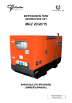
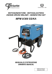
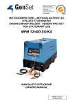
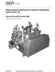
1
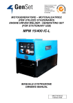
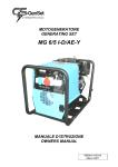
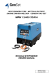
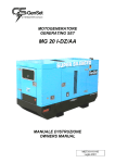
MOTOGENERATORE
GENERATING SET
MG 13000 SS-A-WL/AA
MANUALE D’ISTRUZIONE
OWNERS MANUAL
MI333-01-00-01
Dicembre 2003
Motogeneratore - Generating Set MG 13000 SS-A-WL/AA
1. CARATTERISTICHE TECNICHE / TECHNICAL SPECIFICATIONS
1.1 GENERATORE / GENERATOR
Tipo
Potenza monofase
Frequenza
Sincrono / Synchronous Type
13 kVA 230 V
50 Hz
Single phase power
Frequency
Cos ϕ
0,8
Cos ϕ
Classe isolamento
H
Insulation class
Grado di protezione
IP 23
Mechanical protection
1.2 MOTORE / ENGINE
Tipo motore
Lombardini LDW 1404 Make/Type
Numero cilindri
Cilindrata
4
1372 cm3
Potenza
17 HP
Velocità
1500 r.p.m.
Raffreddamento
Carburante
Capacità coppa olio
Avviamento
Consumo specifico
Acqua – Water
Diesel
3l
Elettrico – Electric
280 gr/kWh
Number of cylinders
Displacement
Power
Engine speed
Cooling
Fuel
Oil sump capacity
Starting system
Specific fuel consumption
1.3 CARATTERISTICHE GENERALI / GENERAL FEATURES
Batteria richiesta
Capacità serbatoio interno
Autonomia carico 75%
Dimensioni (Lu. x La. x H.)
Peso
12 V - 44 Ah
30 l
9 h 30' ~
1450x750x815 mm
348 kg
2
Battery on request
Internal fuel tank capacity
75% Average operating hours
Dimensions (L. x W. x H.)
Weight
MI333-01-00-01
Dicembre 2003
Motogeneratore - Generating Set MG 13000 SS-A-WL/AA
2. DESCRIZIONE DEI COMANDI / CONTROLS DESCRIPTION
2.1 PANNELLO FRONTALE / FRONT PANEL
1
Presa di corrente monofase 230 V 63 A CEE 230 V 63 A EEC single phase power
source
2
Interruttore termico bipolare 63 A
63 A 2 poles circuit breaker
3
Amperometro F.S. 100/5 A
100/5 A ammeter
4
Fusibile 5 A protezione ventole
5 A fan fuse
5
Spia ventole in funzione
Fan on signal lamp
6
Contaore
Hour meter
7
Connettore al pannello logica di comando
µP5
µP5 logic control panel
8
Connettore preriscaldo motore
Engine preheat connector
9
Morsetto di massa per il collegamento a terra Earth clamp connection
3
MI333-01-00-01
Dicembre 2003
Motogeneratore - Generating Set MG 13000 SS-A-WL/AA
3. RICAMBI / PARTS LIST
3.1 PARTI STATORE – STATOR PARTS
4
MI333-01-00-01
Dicembre 2003
Motogeneratore - Generating Set MG 13000 SS-A-WL/AA
Numero Numero
Posizione Codice
Item N° Ordering
N°
1
25.578
2
26.117
3
19.451
4
25.804
5
23.370
6
26.112
7
23.254
8
0464
9
25.892
10
27.105
11
23.365
12
18.192
13
25.894
14
885
15
26.027
16
24.379
Descrizione
Denomination
Statore
Rotore
Disco inox
Piattello per rotore
Diodo
Dissipatore per diodi
Cuscinetto
Anello seeger
Mozzetto per ventola
Ventola lavorata
Base per condensatore
Condensatore 50µF
Protezione per condensatore
Morsetto negativo
Vite a colletto M8x20
Or
Stator
Rotor
Flex plate
Rotor washer
Diode
Dissipator
Bearing
Seeger ring
Fan hub
Fan
Capacitor plate
50µF capacitor
Capacitor cover
Negative clamp
M8x20 screw
O-ring
5
MI333-01-00-01
Dicembre 2003
Motogeneratore - Generating Set MG 13000 SS-A-WL/AA
3.2 FRONTALE (APPARECCHIATURE ELETTRICHE) – FRONTAL (ELECTRIC
EQUIPMENT)
6
MI333-01-00-01
Dicembre 2003
Motogeneratore - Generating Set MG 13000 SS-A-WL/AA
Numero Numero
Posizione Codice
Item N° Ordering
N°
1
27.108
2
522
3
13.036
4
18.315
5
13.410
6
23.737
7
8
23.738
19.186
9
10
11
20.077
23.214
25.890
12
13
14
15
16
24.104
24.439
24.105
25.895
27.171
17
18
19
20
21
22
23
24
25
0336
21.711
21.793
16.305
21.713
15.239
27.109
10.057
12.450
Descrizione
Denomination
Mostrina serigrafata
Portafusibile
Fusibile 5 A
Interruttore termico 63 A
Protezione gomma per termico
Custodia fissa per connettore
multiplo
Frutto presa 16 poli femmina
Presa di corrente monofase 230 V
63 A CEE
Spia indicatore ventola in funzione
Tirante ottone
Targhetta serigrafata per presa
scaldiglia
Custodia fissa diritta
Connettore maschio 4 poli
Connettore femmina 4 poli
Custodia mobile
Piastra supporto relè e trasformatore
amperometrico
Relè 12 V
Fermo per morsettiera componibile
Morsetto componibile
Supporto per interruttore termico
Terminale chiusura morsetto
Contaore
Amperometro F.S.100/5 A
Supporto morsettiera
Trasformatore amperometrico
100/5 A
Aluminium plate
Fuse holder
5 A fuse
63 A circuit breaker
Rubber protection
Multiple pole connector box
7
16 poles female connector
230 V 63 A EEC single phase socket
Fan on signal lamp
Tie rod
Heater plate
Cconnector box
4 poles male connector
4 poles female connector
Connector box
Relay and amperometric transformer
support
12 V relay
Stop single terminal board
Single terminal board
Circuit breaker support
Terminal board cover
Hour meter
100/5 A ammeter
Terminal board support
100/5 A amperometric transformer
MI333-01-00-01
Dicembre 2003
Motogeneratore - Generating Set MG 13000 SS-A-WL/AA
3.3 PARTI LAMIERA – SHETTS PARTS
8
MI333-01-00-01
Dicembre 2003
Motogeneratore - Generating Set MG 13000 SS-A-WL/AA
Numero Numero
Posizione Codice
Item N° Ordering
N°
1
25.866
2
25.867
3
19.795
4
22.341
5
25.868
6
25.900
7
26.100
8
15.662
9
27.113
10
25.870
11
27.114
12
19.100
13
27.110
14
25.872
15
25.873
16
27.104
17
26.102
18
26.113
19
25.874
20
22.654
21
25.878
22
22.744
23
19.868
24
26.075
25
25.879
26
25.880
27
25.881
28
25.882
29
25.883
30
27.112
31
20.715
32
20.831
33
14.247
34
19.005
Descrizione
Denomination
Basamento
Pianale
Rondella rame
Ammortizzatore
Piede motore completo
Supporto alternatore destro
Supporto alternatore sinistro
Distanziale supporto piastra per relè
Parete rivestita
Sportello
Piastra per prolunga flessibile
Maniglia con serratura
Scatola uscita aria
Pannello chiusura
Cornice radiatore
Collettore acqua
Curva flangiata per acqua
Portagomma 1" gas
Radiatore
Tubo corto flessibile (100 l)
Scatola per ventilatori
Anello per ventilatore
Ventilatore
Protezione cavi
Pannello posteriore rivestito
Terminale silenziatore
Silenziatore
Protezione silenziatore
Prolunga flessibile
Pannello superiore
Batteria 12 V 44 Ah
Piastrina fissaggio batteria
Morsetto positivo
Protezione morsetto positivo
Frame
Panel
Copper washer
Shock absorber
Motor bracket
Right alternator bracket
Left alternator bracket
Relay support spacer
Panel
Door
Flexible extension plate
Handle
Box
Panel
Radiator frame
Water collector
Water flange
1” gas rubber older
Radiator
Flex tube (100 l)
Fan box
Fan ring
Fan
Wire protection
Rear panel
Silencer extension
Silencer
Silencer protection
Flexible extension
Upper panel
12 V 44 Ah battery
Battery plate
Positive battery charging clip
Positive charging clip battery
protection
Negative battery charging clip
Positive charging clip battery
protection
Fuel tank
Horizontal upper frame profile
35
36
14.248 Morsetto negativo
19.004 Protezione morsetto positivo
37
38
25.885 Serbatoio carburante
26.103 Cornice orizzontale superiore
9
MI333-01-00-01
Dicembre 2003
Motogeneratore - Generating Set MG 13000 SS-A-WL/AA
Numero Numero
Posizione Codice
Item N° Ordering
N°
39
26.104
40
26.105
41
26.106
42
21.026
43
21.524
44
12.319
45
26.107
46
27.111
47
21.526
48
21.527
49
22.346
50
21.791
51
25.604
52
27.107
53
22.661
54
22.380
55
26.114
56
22.381
57
22.382
58
59
60
22.378
61
17.818
62
22.379
63
22.383
64
65
22.657
66
22.653
67
21.792
68
11.821
69
16.258
70
25.888
71
20.874
72
26.111
73
12.763
74
13.649
75
26.110
76
25.875
77
25.876
78
Descrizione
Denomination
Cornice orizzontale inferiore
Cornice verticale destro
Cornice verticale sinistro
Piastrina rinforzo
Saracinesca 3 vie
Curva maschio/femmia ⅜"
Raccordo portagomma ⅜"
Piastra centrale
Raccordo rapido femmina
Raccordo rapido maschio
Piastra supporto filtro
Raccordo portagomma mandata
Maniglia comando rubinetti
Piastra supporto innesti serbatoio
Staffa tubo olio
Raccordo a tre vie
Raccordo M/F ½”
Raccordo M/M ½”
Prolunga di raccordo
Porta astina livello olio (motore)
Astina livello olio (motore)
Tubo olio
Tappo per tubo scarico olio
Vite forata
Rondella rame
Scaldiglia
Portagomma doppio
Rubinetto ¼“ gas
Raccordo portagomma recupero
Indicatore livello carburante
Tubo
Piastra di ancoraggio
Tappo serbatoio
Supporto relè
Morsettiera
Relè 230 V
Tubo lungo flessibile (200 l)
Lamiera separatrice alternatore
Angolare fissaggio lamiera
separatrice
26.108 Raccordo maschio/femmina 3/8"
10
Horizontal lower frame profile
Right vertical frame profile
Left vertical frame profile
Renforcement plate
3 way cock
⅜” male/female curve
⅜” rubber cable older
Plate
Female rapid attachement
Male rapid attachement
Filter support plate
Rbber older outlet attachement
Handle
Plate
Oil tube support
3 way pipe fitting
½” male/female pipe fitting
½” male/male pipe fitting
Extension
Oil level deep stick older (engine)
Oil level deep stick (engine)
Oil tube
Oil drain screw
Screw
Copper washer
Heater
Double tube holder
¼“ gas cock
Rubber cable older suctionb
Fuel level
Tube
External fixing plate
Cap
Relay support
Terminal board
230 V relay
Flex tube (200 l)
Alternator divider panel
Alternator divider panel fixing plate
3/8 male/female pipe fitting
MI333-01-00-01
Dicembre 2003
Motogeneratore - Generating Set MG 13000 SS-A-WL/AA
Numero Numero
Posizione Codice
Item N° Ordering
N°
79
19.944
80
26.116
81
0923
82
19.372
83
27.106
84
20.039
85
21.597
Descrizione
Denomination
Piastra per relè
Flangia per chiusura terminale
Tappo scarico serbatoio
Piastra per sportello
Griglia
Interruttore stacca batteria
Chiave per interruttore stacca
batteria
Plate for relay
Flang e
Fuel drain screw
Plate for door
Grille
Batteryswitch
Key for battery switch
11
MI333-01-00-01
Dicembre 2003
Motogeneratore - Generating Set MG 13000 SS-A-WL/AA
3.4
QUADRO ELETTRICO AD INTERVENTO AUTOMATICO / AUTOMATIC MAIN
FAILURE PANEL CONTROL
RICAMBI - SPARE PARTS LIST
Numero
Numero
Descrizione
Posizione Codice
Item N°
Ordering N°
26.019 Quadro elettrico ad intervento
automatico MP5 15 kVA 230 V
monofase completo
12
Denomination
MP5 15 kVA 230 V single
phase automatic main failure
panel control assembly
MI333-01-00-01
Dicembre 2003
Motogeneratore - Generating Set MG 13000 SS-A-WL/AA
4.
SCHEMA ELETTRICO / WIRING DIAGRAM
13
MI333-01-00-01
Dicembre 2003
Motogeneratore - Generating Set MG 13000 SS-A-WL/AA
5.
QUADRO ELETTRICO AD INTERVENTO AUTOMATICO /
AUTOMATIC MAINS FAILURE PANEL CONTROL
I quadri elettrici ad intervento automatico
Gen Set, consentono l’avviamento automatico
del gruppo elettrogeno e quindi l’erogazione di
energia elettrica all’utenza, nel giro di pochi
istanti dall’interruzione dell’alimentazione
della rete elettrica principale; l’erogazione di
energia da parte del gruppo elettrogeno viene
immediatamente interrotta al ritorno della
tensione in rete.
The automatic mains failure panel controls
Gen Set the generator operating conditions; it
protects the generator in the case of any
malfunction; it stop the generator when the
mains supply returns and then prepares the
generator for a new start.
I quadri sono dotati di comando e controllo a
microprocessore e corredati di strumentazione
digitale
selezionabile
sul
display
(frequenzimetro, voltmetro batteria, voltmetro
rete/gruppo elettrogeno), comandi di marcia ed
arresto, commutatore per la selezione delle
funzioni operative e led luminosi per le
indicazioni di stato.
The front panel includes: Digital read-out
selection for frequency, battery level,
mains/generator voltage; stop and start
controls; operating functions selection switch;
led warning light for operating conditions
control; hour meter.
Tutti i circuiti operativi di comando, controllo e
regolazione sono compresi in una unica scheda,
dotata di un microprocessore programmabile
che consente di adattare di volta in volta i
parametri di funzionamento del gruppo
elettrogeno alle caratteristiche delle utenze cui
viene asservito.
All circuits, (operating control, checking and
regulation), are controlled by a led
programmable microprocessor which enables
the programming of the functioning
parameters, according to the requirements of
the particular application. The microprocessor
card is positioned on the front panel, making
it easy to replace if it gest mamaged.
La scheda elettronica è montata sul frontale ed
è facilmente sostituibile in caso di avaria. Allo
scopo di evitare danni al sistema operativo del
quadro, derivanti dalla eventuale presenza di
sovratensioni di linea, ogni segnale di ingresso
risulta elettricamente disaccoppiato dai circuiti
elettronici del sistema stesso.
Every on-going electrical signal is protected
from any possible damage caused by mains
over voltages. All the panels are provided
with a four pole changing over, an automatic
battery charger and a multiple cable for the
connection with the generator.
14
MI333-01-00-01
Dicembre 2003
Motogeneratore - Generating Set MG 13000 SS-A-WL/AA
Sono inoltre disponibili su richiesta numerose
altre funzioni opzionali, fra le quali:
Other optional features available on request
are:
• Predisposizione per il trasferimento a
distanza dei segnali di allarme e di stato del
generatore.
• long distance transmission remote control
facilites for the alarm and operating
conditionns.
• Visualizzazione
un’interfaccia.
• PC interface.
su
P.C.
tramite
• timer device for operating control program.
• dispositivo timerizzato di programmazione
delle prove di funzionamento.
15
MI333-01-00-01
Dicembre 2003
Motogeneratore - Generating Set MG 13000 SS-A-WL/AA
5.1 FUNZIONAMENTO / OPERATION
L’apparecchiatura di comando del gruppo
elettrogeno deve essere inserita sull’impianto
elettrico del circuito utilizzatore. Detta
apparecchiatura fa intervenire il gruppo
elettrogeno alla mancanza di tensione della rete.
Una memoria elettronica di cui è dotata
l’apparecchiatura, programma l’avviamento del
gruppo elettrogeno con una successione di 3
impulsi di corrente dalla batteria al motorino di
avviamento della durata di 7 secondi cadauno
intervallati da 4 secondi.
The generating set control system must be
connected to the main supply circuit. When
the control system detects a fault of the main
supply, e. g. the user electric circuit from the
main supply and acts in order to start the
generating set. The starting process is
accomplished with a sequence of three trials
with a duration of 7 seconds each with a pause
of 4 seconds between a trial and the
following. When the diesel engine is running,
the control system stops the trials.
In order to make the engine work properly, the
user electric circuit is not connected to the
generating set immediately, but only when a
pre-heating time is elapsed, the pre-heating
period is adjustable, up to a maximum of 2
minutes.
Avviato il motore cessano gli impulsi. Il
generatore non eroga potenza sino ad un
massimo, regolabile, di 2 minuti.
Trascorso il tempo prestabilito, il generatore è
pronto a erogare.
Once the pre-heating period is elapsed the
generating set is ready to supply electric
power to the user circuit and the control
system to the generating set.
Al
ritorno
della
corrente
di
rete
automaticamente il carico passa sotto la linea di
rete e contemporaneamente il gruppo si ferma.
L’apparecchiatura è munita di teleruttori
interbloccati che non consentono l’inserimento
del gruppo elettrogeno in presenza della
corrente di rete.
The control system remains connected to the
main supply. When the faulty conditions
disappear e.g. the main voltage return to its
nominal value, the user electric circuit is
commutated from the generating set to the
main supply, and the generating set is
stopped.
L’apparecchiatura è dotata di un “carica
batteria”
elettronico
che
mantiene
permanentemente in condizioni di massima
carica la batteria del gruppo elettrogeno
attingendo corrente dalla rete.
The system is equipped with interlocked
electro-mechanical devices that prevent the
user from operation the generating set when
the main supply is working properly.
Tale dispositivo elettronico ha la caratteristica
di non danneggiare la batteria anche se questa
rimane inserita per lunghissimo tempo.
The system is provided with a electronic
battery charger in order to ensure the battery
efficieny. The battery charger is designed in
order to remain permanently connected to the
battery, without damaging it.
16
MI333-01-00-01
Dicembre 2003
Motogeneratore - Generating Set MG 13000 SS-A-WL/AA
5.2 INSTALLAZIONE / INSTALLATION
L’apparecchiatura di comando del gruppo
elettrogeno va collegata in serie con la linea di
arrivo della rete: significa che è necessario
sezionare l’impianto del circuito utilizzatore
con la linea della rete, subito dopo il contatore e
relative protezioni come mostra lo schema a
seguito.
The generating set control system must be
placed between the main supply and the user
electric circuit, after the consumption measure
system and the electric protection devices as
shown in the figure below.
Attenzione : Detta apparecchiatura e gruppo
elettrogeno funzionano regolarmente solo per
rete monofase a tensione 230 V.
Warning : The generating set control system
and the generating set itself is designed to
operate properly with a single-phase 230 V
main supply.
17
MI333-01-00-01
Dicembre 2003
Motogeneratore - Generating Set MG 13000 SS-A-WL/AA
6. ISTRUZIONE PER L’USO / OPERATING INSTRUCTIONS
6.1 INSTALLAZIONE / INSTALLATION
Il motogeneratore è dotato di un serbatoio
interno da 30 l. E' possibile anche collegare un
serbatoio esterno agendo sul sistema di
alimentazione carburante posto all'interno del
generatore.
The generating set is equipped with a 30 l.
internal fuel tank. It is possible to install an
external fuel tank operating on the fuel
feeding system placed inside the generating
set canopy.
Per installare il serbatoio esterno :
To install the external fuel tank:
Collegare i tubi di alimentazione (raccordo R1)
e di recupero gasolio (raccordo R2) ad un
serbatoio esterno (fig.1).
Connect the fuel inlet (R1) and outlet (R2)
pipe to a fuel tank (fig. 1).
Fig.1
18
MI333-01-00-01
Dicembre 2003
Motogeneratore - Generating Set MG 13000 SS-A-WL/AA
Portare il sistema di alimentazione carburante
in posizione 2 indicata in fig.2 agendo sulle
apposite maniglie di regolazione.
Place the fuel feeding system on the position
2 shown in fig.2 operating on the regulation
handles.
Fig.2
E’ possibile fissare il generatore tramite gli
appositi fori situati sulle piastre di appoggio del
telaio.
It is possible to mount the generator to the
floor by means of the holes position on the
below the frame.
6.2 MESSA A TERRA / EARTH CONNECTION
Effettuare la messa a terra del gruppo tramite il
morsetto 9 posto sul retro del generatore.
Connect the unit to the earth, means of the 9
clamp .
19
MI333-01-00-01
Dicembre 2003
Motogeneratore - Generating Set MG 13000 SS-A-WL/AA
6.3 IMPIEGO DEL GRUPPO ELETTROGENO CON APPARECCHIATURA DI
COMANDO / AUTOMATIC MAINS FAILURE GENERATING SET OPERATING
INSTRUCTION
Collegare il connettore della logica MP5 con il
connettore 7 del generatore, viene fornito un
cavo della lunghezza di 5 metri già predisposto
per la connessione.
Collegare la presa monofase 1 CEE 230 V 63 A
del generatore con una spina CEE 230 V 63 A
(non fornita) alla morsettiera U-NG posta
all’interno del quadro di comando MP5.
Provvedere ad installazione effettuata ad una
simulazione MANUALE di intervento del
gruppo in condizione di massimo carico
presunto, questo al fine di verificare la
compatibilità tra potenza massima disponibile
al gruppo e la potenza richiesta.
Ad esito positivo di collaudo predisporre il
selettore modi di funzionamento del gruppo in
posizione AUTO. Da questo momento il
gruppo è pronto ad intervenire ad ogni blackout.
Connect the connector of the MP5 generating
set control system with the generating set
connector 7 a 5 m. connection cable is
provided with the generating set.
Connect the generating set single phase socket
1 EEC 230 V 63 A to the U-NG clamps
places on the terminal board inside the control
system MP5.
When the installation is terminated. set the
control system in MANUAL mode and
gradually apply the maximum expected load
in order to verify the correct matching
between generating set power and maximum
power absorption.
When the maximum load test is succesfully
completed, set the control system in AUTO
mode. The control system is working properly
and the generating set is ready to start ina case
of main supply failure.
Per il funzionamento del gruppo con la
apparecchiatura di comando, in MANUALEAUTOMATICO-PROVA vedere le istruzioni
allegate alla logica.
Please refer to the MP5 Control system
instruction manual in order to obtain more
detailed information on operating of the
generating set under MP5 control.
20
MI333-01-00-01
Dicembre 2003
Motogeneratore - Generating Set MG 13000 SS-A-WL/AA
6.4 SCHEMA DI COLLEGAMENTO TRA IL GRUPPO ELETTROGENO E IL QUADRO
DI COMANDO MP5 / MP5 CONTROL PANEL CONNECTION
6.5 AVVERTENZE E CONSIGLI UTILI / WARNING
Se il generatore viene posto in un locale, fare
attenzione che l’ambiente sia ben ventilato,
eventualmente utilizzare degli aspiratori per
consentiere un corretto ricambio d’aria.
If the generator must operate in a close
environment. The environment must be well
wentilates. If natural ventilation is not
sufficient fans must be used.
É importante conservare il motore in perfette
condizioni, si consiglia perciò la rigorosa
osservanza delle norme di manutenzione
riportate nel catalogo “Uso e manutenzione”
del motore onde evitare inconvenienti ed una
conseguente perdita di potenza del generatore.
In order to preserve the engine performance
Gen Set strongly suggests to follow the
maintenance operations and the maintenance
schedule reported in the engine manufacturer
“Use and maintenance” user manual. Poor
maintenance could result in a shorter period of
operation and in performance decrease.
21
MI333-01-00-01
Dicembre 2003
Motogeneratore - Generating Set MG 13000 SS-A-WL/AA
6.6 DISEGNO DI COLLEGAMENTO TRA IL GRUPPO ELETTROGENO E RELATIVE
APPARECCHIATURE / INSTALLATION GENERATING SET
22
MI333-01-00-01
Dicembre 2003
Motogeneratore - Generating Set MG 13000 SS-A-WL/AA
6.7 CAUSE DI SCARSO RENDIMENTO DEL MOTORE / CAUSES OF ENGINE POOR
PERFORMANCE
SOSTITUZIONE DELLA CARTUCCIA
DEL FILTRO DEL COMBUSTIBILE
FUEL
FILTER
REPLACEMENT
CARTRIDGE
Sostituire la cartuccia del filtro del carburante
con una nuova ogni 250 ore circa di
funzionamento.
Replace the fuel filter cartridge with new one
every 250 operating hours or so.
Operazioni:
Operations:
• Togliere e gettare il filtro combustibile
• Remove and replace fuel filter
• Applicare un leggero strato di gasolio sulla
guarnizione, quindi serrare a fondo con le
mani la cartuccia in posizione.
• Apply fuel oil thinly over the gasket and
tighten the cartridge into position handtight.
OLIO DEL MOTORE
ENGINE OIL
• CAUTELA: Per evitare lesioni personali,
accertarsi di spegnere il motore prima di
controllare il livello dell’olio e prima di
cambiare la cartuccia del filtro dell’olio.
• CAUTION: To avoid personal injury, be
sure to stop the engine before checking the
oil level, changing the oil and the oil filter
cartridge.
• NOTA: Non mancare di ispezionare il
motore collocandolo su un posto in piano.
Se collocato su un posto in pendenza, non è
possibile misurare accuratamente la quantità
dell’olio.
CONTROLLO
DEL
LIVELLO
E
RABBOCCO DELL’OLIO DEL MOTORE
Operazioni :
• Controllare il livello dell’olio del motore
prima dell’avviamento, oppure quando sono
passati più di 5 minuti dall’arresto.
• Disinserire l’indicatore del livello dell’olio,
pulirlo bene strofinandolo e reinserirlo.
• NOTE: Be sure to inspect the engine,
locating it on a horizontal place. If placed
on gradients, accurately, oil quantity may
not be measured.
• Estrarre di nuovo l’indicatore del livello
dell’olio e controllare il livello dell’olio.
• Take the oil level gauge out again, and
check the oil level.
• Se il livello dell’olio è troppo basso, togliere
il tappo dell’olio e aggiungere olio fino a che
raggiunge il livello prescritto.
• If the oil level is too low, remove the oil
filter plug and add new oil to the
prescribed level.
CHECKING LEVEL AND ADDING
ENGINE OIL
Operations
• Check the engine oil level before starting
or more than five minutes after stopping.
• Detach the oil level gauge, wipe it clean
and reinstall it.
23
MI333-01-00-01
Dicembre 2003
Motogeneratore - Generating Set MG 13000 SS-A-WL/AA
• Aggiunto l’olio aspettare più di 5 minuti e
controllarne di nuovo il livello. Questo
tempo è necessario perché l’olio raggiunga
la coppa dell’olio.
• After adding oil, wait more than 5 minutes
and check the oil level again. It takes same
time for the oil to come down to the oil
pan.
CAMBIO DELL’OLIO MOTORE
CHANGING ENGINE OIL
• Cambiare olio dopo le prime 50 ore di
funzionamento iniziale, successivamente,
ogni 125 ore.
Change oil after the initial 50 hours of
operation and every 125 hours thereafter.
Operazioni :
Operations :
• Rimuovere il tappo di scarico dell’olio e
scaricare l’olio vecchio. Lo scarico dell’olio
è più facile e completo se viene eseguito
quando il motore è caldo..
• Remove the drain plug and drain all the old
oil. Drain oil easier and completely while
the engine is hot.
• Riempire la coppa fino al contrassegno
disegnato sull’asta di livello con olio
lubrificante nuovo e pulito di gradazione
approvata..
• Fill the sump to the mark on the dipstick
with new and clean lubrification oil of an
approved grade.
SOSTITUZIONE DELLA
DEL FILTRO DELL’OLIO
REPLACING
CARTRIDGE
CARTUCCIA
THE
OIL
FILTER
• CAUTELA : Per evitare lesioni personali :
cambiare la cartuccia del filtro dell’olio solo
a motore spento e lasciar raffreddare
sufficientemente il motore; l’olio può essere
molto caldo e ustionare.
• CAUTION : To avoid personal injury be
sure to stop the engine before changing the
oil filter cartridge and allow engine to cool
down sufficiently; oil can be hot and can
burn.
Operazioni :
Operations
• Sostituire la cartuccia del filtro dell’olio
ogni 250 ore di servizio.
• Replace the oil filter cartridge every 250
hours of operation.
• Togliere e gettare il filtro olio.
• Remove and replace oil filter.
• Oliare leggermente la guarnizione per la
nuova cartuccia.
• Apply a film of oil to the gasket for the
new cartridge.
• Avvitare a mano la cartuccia. Quando la
guarnizione arriva a contatto della superficie
di tenuta, stringere la cartuccia quanto basta
e sempre a mano. Questo perché usando una
chiave la cartuccia verrebbe serrata troppo.
• Screw in the cartridge by hand. When the
gasket contacts the seal surface, tighten the
cartridge enough by hand. Because, if you
tight the cartridge with wrench, it will be
tightened too much.
24
MI333-01-00-01
Dicembre 2003
Motogeneratore - Generating Set MG 13000 SS-A-WL/AA
• Dopo che la cartuccia è stata sostituita, di
solito il livello dell’olio si abbassa un po’.
Per questo motivo, far girare il motore per
un po’ di tempo e controllare se ci sono
perdite di olio dalla guarnizione di tenuta
prima di controllare il livello dell’olio. Se
necessario, aggiungere dell’olio.
• After the new cartridge has been replaced,
the engine oil level normally decreases a
little. Thus ,run the engine for a while and
check oil leaks through the seal before
checking the engine oil level. Add oil if
necessary.
• NOTA : Strofinare via completamente l’olio
appiccicato alla macchina.
• NOTE : Wipe off any oil sticking to the
machine completely.
RADIATORE
RADIATOR
• Il refrigerante, se rabboccato completamente
prima di mettere in marcia il motore, dura
una giornata di lavoro. Pertanto il livello del
refrigerante deve essere regolarmente
controllato prima di ogni messa in funzione.
Coolant will last for one day’s work if filled
all the way up before operation start. Make it
a rule to check the coolant level beforeevery
operation.
• AVVERTENZA : Per evitare lesioni
personali non rimuovere il tappo del
radiatore quando il motore è caldo. In
seguito, allentare leggermente il tappo fino
al fermo per scaricare l’eccesso di pressione,
quindi rimuoverlo completamente.
• WARNING : To avoid personal injury do
not remove the radiator cap when the
engine is hot. Then loosen cap slightly to
the stop to relieve any excess pressure
before removing cap completely.
CONTROLLO DEL LIVELLO
REFRIGERANTE,
AGGIUNTA
REFRIGERANTE
CHECKING COOLANT
ADDING COOLANT
DEL
DI
LEVEL
,
Operazioni :
Operations :
• Rimuovere il tappo del radiatore, e verificare
che il refrigerante raggiunga il bocchettone
di rifornimento.
• Remove the radiator cap, and check to see
that coolant reaches the supply port.
• Quando il livello del refrigerante si abbassa
a causa della evaporazione, aggiungere solo
acqua fino a raggiungere il livello di pieno.
• When the coolant level drops due to
evaporation, add water only up to the full
level.
• Controllare il rubinetto di scarico.
• Check to see that drain cock.
IMPORTANTE : Se occorre rimuovere il
tappo del radiatore, seguire le precauzioni
riportate sopra e riavvitarlo saldamente.
Dovesse esserci una perdita d’acqua, consultare
il concessionario LOMBARDINI.
IMPORTANT : If the radiator cap has to be
removed, follow the caution above and
securely retighten the cap. If water should be
leak, consult your local LOMBARDINI
dealer.
25
MI333-01-00-01
Dicembre 2003
Motogeneratore - Generating Set MG 13000 SS-A-WL/AA
CAMBIO LIQUIDO RAFFREDDAMENTO
CHANGING COOLANT
Operazioni :
Operations :
• Per scaricare il refrigerante, aprire sempre il
rubinetto
di
scarico
e
aprire
contemporaneamente il tappo del radiatore.
Lo scarico completo dell‘acqua è
impossibile se il tappo del radiatore viene
tenuto chiuso.
• To drain coolant, always open both drain
cock and simultaneously open the radiator
cap as well. With the radiator cap kept
closed, a complete drain of water is
impossible.
CONTROLLO FILTRO DELL’ARIA
AIR CLEANER CHECKING
Se l’elemento del filtro dell’aria impiegato in
questo motore è del tipo secco, non deve mai
essere oliato
As the element of the air cleaner employed on
this engine is a dry type, never apply oil to it.
• In condizioni normali d’esercizio, la valvola
d’evacuazione (fig.9 n°1) deve essere aperta
una volta alla settimana-oppure tutti i giorni
se viene usata in ambiente polveroso-in
modo da rimuovere la polvere e le piccole
impurità .
• Open the evacuator valve (fig.9 n°1) once a
week under ordinary conditions-or daily
when used is in a dusty place-to get rid of
large particles of dust and dirt.
Operazioni :
Operations:
• Aprire il filtro e togliere la massa filtrante.
• Open air cleaner and remove element.
• Battere l’elemento su una superficie dura,
leggermente e ripetutamente, in modo da
eliminare la sporcizia in esso. E’
sconsigliabile soffiare con aria compressa
l’elemento filtrante in carta. Pulire
accuratamente il coperchio e il supporto
filtro.
• Lightly and repeteatedly tap the element on
a hard surface to eliminate all excess dirt.
Do not blow the paper filter element with
compressed air to clean.
• Evitare di toccare l’elemento se non per
pulirlo.
• Avoid touching the element except when
cleaning.
• Se la massa filtrante è stata pulita altre volte,
o se è irrimediabilmente intasata gettarla e
sostituirla.
• If the filtering element has been already
cleaned other times, or if it is irreparably
clogged, throw it away and replace.
• Rimontare massa filtrante e filtro aria.
• Reassemble the filtering element and air
cleaner.
• Accertarsi che il filtro sia montato in modo
corretto altrimenti polvere ed altro possono
entrare nei condotti aspirazione.
• Make sure that the filter is mounted in the
correct way otherwise dust and other
impurities could ilfiltrate into the intake
ducts.
26
MI333-01-00-01
Dicembre 2003
Motogeneratore - Generating Set MG 13000 SS-A-WL/AA
7. NORME GENERALI DI IMPIEGO / GENERAL USE INSTRUCTIONS
Leggere attentamente le istruzioni d’uso; operare secondo le prescrizioni vigenti
nel paese di utilizzo.
7.1
Read the instructions carefully; proceed according to the regulations in use in
the country where the machine will operate.
MOVIMENTAZIONE E TRASPORTO / TRANSPORTATION
Durante il trasporto nei luoghi di utilizzo la macchina deve essere fissata in modo
stabile e legata all’automezzo. Sollevare la macchina mediante l’apposito gancio di
sollevamento, se il modello lo prevede, oppure sollevarla con il muletto facendo
attenzione ad inforcarla in modo che il peso sia bilanciato. Durante tali operazioni
è sconsigliato sostare nelle immediate vicinanze o nel raggio di manovra; sono
sconsigliati posteggi della macchina in sospensione aerea.
Nel caso in cui la macchina venga spedita con il gruppo ruote smontato,
provvedere al montaggio dello stesso nelle apposite sedi previste sulla macchina,
prima della messa in funzione.
Durante il normale uso della macchina su ruote, sarà attenzione dell’operatore
posizionare l’unità in modo che non intervengano spostamenti non desiderati.
7.2
The machine must be fixed carefully to the motor vehicle if it has to be moved to
the place of use. Raise the machine using the lifting eye if the model foresees it;
otherwise, lift it using a forklift, taking care that the weight is well balanced on
the two forks. It is advised not to stay in the range of action during these
operations; furthermore we suggest not to keep the machine hung up for long.
If the machine is delivered without the wheels on, mount them before switching
the machine on.
During the normal use of the machine mounted on wheels (in a building yard or
anywhere), the operator must ascertain that the machine is weel placed in order
to avoid unforeseen displacement.
MESSA IN SERVIZIO / CAUTION
Attenzione: il gruppo è fornito SENZA olio motore. Provvedere al rifornimento
con olio multigrado “10 W 40” indicato per temperature da - 20° C ad oltre 40° C
nella quantità indicata nelle specifiche motore indicate dalle CARATTERISTICHE
TECNICHE.
Attenzione: se la vostra macchina è raffreddata ad acqua (vedere nelle
CARATTERISTICHE TECNICHE del motore) provvedere al rifornimento del
circuito motore - radiatore con una soluzione di 50% acqua e 50% liquido antigelo
nella quantità indicata dalle specifiche motore.
Attenzione: il gruppo è fornito con batteria scarica e priva di acido. Provvedere al
suo riempimento utilizzando acido solforico in soluzione con concentrazione 30% 40% fino alla copertura degli elementi. Durante questa operazione si consiglia
l’uso di guanti; il contatto accidentale con la soluzione di acido solforico dovrà
essere lavato immediatamente con acqua fredda e se necessario si dovrà consultare
il medico
Attenzione: non togliere i cavi della batteria quando la macchina è in moto, vi è il
rischio di danneggiare il corretto funzionamento della macchina.
Attenzione: PRIMA DI AVVIARE LA MACCHINA il centro-stella, o il punto
degli avvolgimenti che ne svolge la funzione, DEVE essere collegato a terra
rigidamente (senza interruttori o altri dispositivi che possano interrompere il
collegamento elettrico) mediante il morsetto adibito a questo scopo che è messo a
disposizione sulla struttura della macchina ed è identificato con il simbolo:
Be careful: the generating set or the welder is furnished WITHOUT lube oil.
Provide the machine with “10 W 40” multigrade oil indicated for temperatures
from - 20° C to 40° C in the quantity indicated in the engine SPECIFICATION
section.
Be careful: if the machine is fitted with a water cooled engine fill the radiator
circuit with a solution made up by 50% water and 50% antifreeze liquid inthe
quantity indicated i the engine SPECIFICATION section.
Attenzione: durante i normali trasferimenti si considerino le istruzioni riportate
nella sezione MOVIMENTAZIONE E TRASPORTO prestando attenzione nel
limitare eccessive inclinazioni della macchina che possono causare la fuoriuscita di
acidi della batteria.
Be carefull: for normal transportation, follow the instructions as specified in the
TRASPORTATION section. Make sure that the machine doesn’t overturn in
order to avoid spill of acids from the battery.
7.3
Be careful: the generating set is furnished with flat battery and without acid. Fill
it using sulphuric acid in a 30% - 40% concentrated solution up to the complete
covering of the elements. During this operation, we suggest the operator to use
the gloves; the accidental contact with the sulphuric acid solution must be
washed up immediately with cold water and, if necessari, a doctor must be
consulted.
Be carefull: don’t disconnect battery cables when the engine runs. This coud
result in serious damages to the machine.
Be carefull: BEFORE OPERATING THE MACHINE the neutral, or the
equivalen winding point, MUST be connected effectively to the earth (without
any switch or other device that may interrupt the electric connection) from the
earth clamp available on the machine, and identified by the symbol:
RODAGGIO / RUNNING IN
Per le prime 50 ore di funzionamento della macchina, per consentire un buon
rodaggio del motore, non prelevare oltre il 70% della potenza massima indicata
nelle specifiche tecniche.
7.4
For the first 50 hours of operation of the machine do not employ more than 70%
of the maximum power indicated in the technical specifications. In this way, a
proper engine running in is guaranteed.
AVVIAMENTO E FUNZIONAMENTO / STARTING AND WORKING
Effettuare la messa a terra della macchina (vedi ISTRUZIONE PER L’USO).
Se il modello di macchina NON è dotato di interruttore differenziale la presa
disponibile sono da utilizzarsi ESCLUSIVAMENTE per effettuare un
collegamento sicuro ad un quadro di distribuzione dotato di tutte le protezioni
previste dalle leggi vigenti
Verificare che i cavi del vostro utilizzatore siano in perfetta efficienza.
Assicurarsi che tutti gli interruttori, collegati e regolazioni siano nella posizione
prevista per l’avviamento (vedi ISTRUZIONE PER L’USO E DESCRIZIONE
DEI COMANDI).
Operare in ambiente ben ventilato preoccupandosi che i gas di scarico ed eventuali
fumi di saldatura (nel caso di motosaldatrici) non ristagnano nell’ambiente di
lavoro; tenere la macchina lontano da muri o altri ostacoli per avvitare ricicli d’aria
o di gas che ne provocherebbero il surriscaldamento. Nel caso si dovesse operare
in locali chiusi, utilizzare degli aspiratori per garantire un corretto ricambio d’aria.
Make the earth connection (see the USE INSTRUCTIONS).
If the machine model IS NOT equipped with a earth leakege circuit breaker the
available socket is intended ONLY for connecting the machine to a switch
board equipped with all protection devices imposed by current law regulations.
Check the perfect state and efficiecy of the cables.
Make sure that all the switches, electric connections and regulations are inthe
right position for the starting (see USE INSTRUCTIONS and CONTROL
PANELS DESCRIPTIONS).
While welding, eyes and body must be protected by gloves, maskes Use the
machine in well ventilated places, taking care that the exhaust gas and the
welding smokes eventually produced (where welders are used) do not stagnate.
Keep the machine away from walls or other kind of obstacles i order to avoid air
or gas recycling. If the machine is employed in closed places, use aspirators in
order to guarantee a proper air recycling.
27
MI333-01-00-01
Dicembre 2003
Motogeneratore - Generating Set MG 13000 SS-A-WL/AA
Durante la saldatura proteggere gli occhi ed il corpo con guanti, maschere e tute
adeguate (nel caso di motosaldatrice).
I rifornimenti di carburante non devono essere eseguiti fumando o in presenza di
fiamme libere e devono essere effettuati con motore spento.
Non riempire al massimo il serbatoio e pulire eventuali fuori uscite di carburante.
While welding, eyes and body must be potected by gloves, maskes and proper
clothes.
The fuel refill must not be made while smoking or close to flames. This
operation must be done when the engine is switched off.
Do not fill the tank at its maximum level and clean up the fuel eventually
overflowed.
Check daily if there is loss of fuel or lubrificating oil on the ducts or on the
engine.
For machines provided zith liftable canopy insert the foreseen security sistems in
order to avoid injures caused by an unexpected closure.
Controllare quotidianamente che non vi siano perdite di combustibile o di
lubrificanti lungo le canalizzazioni o sul motore.
Nelle macchine dotate di cofanature apribili assicurarsi di inserire i dispositivi di
bloccaggio previsti per evitare incidenti dovuti alla chiusura accidentale
7.5
USI PROIBITI / FORBIDDEN USE
Non collegare la macchina alla rete elettrica commerciale.
Non operare vicino a materiale infiammabile o in presenza di gas e vapori esplosivi
Do not connect the machine to the commercial electric network.
Do not work close to inflammable materials or where there are explosive gas
and vapours.
Do not work in narrow and badly ventilated places.
Do not work without using the protections placed in their proper positions and
in perfect conditions.
Do not touch the exhaust muffler and the parts of the engine next to it.
Do not make service operations while the engine is running.
Any service made on the electric parts must be done when the engine is stopped
and by specialized technicians.
Keep away from the moving parts of the engine while working and do not
approach the machine with free and too long clothes.
Non operare in luoghi ristretti o poco aerati.
Non operare senza le protezioni previste nella loro posizione e nelle perfette
condizioni.
Non toccare le parti della marmitta e le parti del motore ad essa vicine.
Non eseguire interventi di manutenzione a motore avviato.
Ogni intervento sulle parti elettriche deve essere effettuato a motore spento e da
personale specializzato.
Tenersi lontano da parti in movimento e non avvicinarsi con indumenti liberi o
troppo lunghi.
7.6
MANUTENZIONE E PULIZIA / SERVICE AND CLEANING
E’ consigliata una periodica pulizia della macchina onde evitare depositi di
sporcizia che ne possono compromettere l’efficienza.
La frequenza di tale operazione è valutabile in funzione della zona d’impiego, si
consiglia comunque di prestare particolare attenzione alla manutenzione di:
LIVELLO OLIO, FILTRO OLIO, FILTRO ARIA, FILTRI CARBURANTE,
LIVELLO ACQUA RADIATORE, SCAMBIATORI DI CALORE.
Per le modalità e la frequenza consultare il MANUALE d’USO E
MANUTENZIONE del motore e le CARATTERISTICHE TECNICHE. Le
operazioni di manutenzione straordinaria che esulano da quelle citate, necessitano
dell’intervento di personale specializzato (vedere l’elenco dei centri di assistenza).
7.7
TARATURE E REGOLAZIONI / ADJUSTMENT AND REGULATIONS
I comandi per le regolazioni necessarie all’uso sono installati sul pannello di
comando e descritti all’interno della DESCRIZIONE DEI COMANDI.
E’ pertanto sconsigliato l’intervento della macchina da parte di personale non
specializzato.
Attenzione: eventuali tarature non corrette dei normali parametri previsti
all’origine possono compromettere l’affidabilità stessa della macchina.
7.8
FERMO TEMPORANEO / TEMPORARY STANDSTILL
Qualora si debba fermare la macchina per un lungo periodo di tempo (maggiore di
un anno) è consigliato lasciare i liquidi quali: olio motore, acqua radiatore e
carburante, onde evitare ossidazioni.
Alla ripresa in esercizio si dovranno: sostituire i liquidi, ripristinare la batteria,
ispezionare le cinghie e il loro stato, ispezionare le tubature e i giunti in gomma e
la loro tenuta e ispezionare visivamente i cablaggi elettrici.
7.9
DEMOLIZIONE / SCRAPPING
Al fine di salvaguardare l’ambiente naturale è opportuno provvedere alla raccolta
dell’olio, del combustibile e della batteria che dovranno essere smaltiti nelle sedi e
nelle modalità conformi alle leggi vigenti.
Per l’elenco completo dei materiali si veda la scheda allegata:
MATERIALI FERROSI:
acciaio, ghisa, alluminio, rame, ottone compongono strutture portanti , motore,
alternatore, trasformatori
MATERIALI PLASTICI:
gomma, bakelite, epovit, lexan compongono strumentazione, manicotti motore,
morsettiere e connettori, serbatoi, tappi, ruote, antivibranti, contenitori
condensatori, ventole, cinghie, filtri e guaine.
MATERIALI ELETTRONICI:
componenti vari, diodi, resistenze, semiconduttori, pannelli elettronici.
MATERIALI VARI:
lana di roccia, rivestimenti fonoassorbenti.
MATERIALI LIQUIDI:
gasolio o benzina, liquidi antigelo, acido batteria.
We suggest a frequent cleaning of the machine since the presence of dirt can
compromise the efficiency of the machine. The frequency of this operation
tightly depends on the place where the machine is used. We advise, anyway. to
pay special care to the service of:
OIL LEVEL, OIL FILTER, AIR FILTER, COOLING LIQUID LEVEL,
COOLING LIQUID LEVEL, HEAT EXCHANGER, VENTILATION DUCTS
AND INTAKES, BATTERY
Consult the ENGINE USE AND SERVICE manual and the SPECIFICATION
section to know how and when it is useful to do it. The extraordinary service
operations not mentioned hereabove require the aid of specialized technicians
(see the assistance centre list).
All the necessary controls are located on the main control panel and they are
properly explained in the section FRONT PANEL DESCRIPTIONS.
We advise the operator against tempering with the engine or the electric part if
not specialized.
Be careful: eventual modifications of the normal parameters originally foressen,
can compromise the reliability of the machine.
If the machine has to be stopped for a long period (more than one year), we
suggest to leave the motor oil and the fuel in and the water in the radiator in
order to avoid oxydizing effects.
When the machine turns to work again, the liquids must be replaced, the battery
must be charged; the belts and their statem the pipes, the rubber hoses and their
resistance must be checked and a visual inspections of the electric connections
must be done.
In order to preserve the environnement, it is advised to dispose of the oil, the
fuel and the bettery that will be destroyed in proper places and ccording to the
current laws. For the complete range of the materialsm see the list below:
FERROUS MATERIALS:
steel, cast iron, aluminium, copper, brass are udes in the bearing structure of
engine, alternator, transformers, etc.
PLASTIC MATERIALS:
rubber, bakelite, epovit, lexan are used for the instruments, engine pipes,
junction boxes and connectors, fuel tank, fuel cap, wheels, antivibration damper,
condenser housing, fans, belts, filters and hoses.
ELECTRONIC MATERIALS:
various components, diodes, resistances, electronic panels.
VARIOUS MATERIALS:
rock woll, sound proofing materials.
LIQUIDS:
fuel, gasoline, cooling liquids, battery acid.
28
MI333-01-00-01
Dicembre 2003
Motogeneratore - Generating Set MG 13000 SS-A-WL/AA
8. SIMBOLI/SYMBOLS
Condizioni Di Carica Batteria
Battery Charging Condition
Olio Motore
Engine Oil
Temperatura Refrigerante Motore
Engine Coolant Temperature
Temperatura Olio Motore
Engine Oil Temperature
Livello Carburante
Fuel Level
Dispositivo Per L’avviamento A
Freddo
Preriscaldamento Del Diesel
Chocke, Cold Starting Aid
Saldatura In Generale
Welding
Saldatura Ad Arco Manuale
Manual Metal Arc Welding
Saldatura Mig/Mag
Mig/Mag Welding
Saldatura Tig
Tig Welding
Polarità Positiva
Positive Polarity
Polarità Negativa
Negative Polarity
Marcia, Inserzione, Messa In Tensione
On (Power)
Arresto, Disinserzione, (Messa Fuori
Tensione)
Terra Di Protezione
Off (Power)
Regolatore Min-Max
Min-Max Regulator
Corrente Alternata
Alternating Current
Corrente Continua
Direct Current
Generatore Monofase c.a.
230 (240)V - 110V 50Hz
Single Phase Generator a.c.
230 (240)V - 110V 50Hz
Generatore Trifase c.a.
400 (415)V 50Hz
Non Toccare: Zona Calda
Three Phase Generator a.c.
400 (415)V 50Hz
Do Not Touch: High Temperature Zone
Presenza Tensione
Voltage On
29
Diesel Pre-Heat
Protective Earth (Ground)
MI333-01-00-01
Dicembre 2003
Motogeneratore - Generating Set MG 13000 SS-A-WL/AA
9. CENTRI ASSISTENZA ITALIA / ITALIAN SERVICES CENTERS
ASSISTENZA
ASSISTANCE
VALLE D’AOSTA
Off. Elettromeccanica
Menegolo
O.r.m.e.
PIEMONTE
RG Electrix s.n.c. di Riboldazzi
& C.
R.I.M.E.M. s.n.c
Tecnocontrolli
G.B. Elettrotecnica. Industriale
s.n.c.
LIGURIA
C.R.E. s.n.c. di Marchello e
Gotelli
Lanteri
LOMBARDIA
Ghirardello Carlo Antonio
Luciano Miotto
Imp. Elettrici Clivati Umberto
s.a.s.
Carnevali Ivo
Elettromeccanica
Elettroriparazione Pezzaglia
I.C.I.A.M.s.n.c.
F.lli Bracchi s.n.c.
C.R.E.
TRIVENETO
Elettromeccanica Trevigiana
s.n.c.
Barison C. off. Elettrotec.
Macchine Elettriche
Elettromeccanica Amadori
Centro Saldatura s.n.c.
Z.R. s.r.l.
Nuova Elettromeccanica coop.
a.r.l.
Tecno Service Romanelli
Elettromeccanica Alto Adige
s.n.c.
Molinaro Guerrino & Figlio
s.n.c.
EMILIA ROMAGNA
Casadio Vezio & C. s.n.c.
F.lli Cesari s.n.c.
Eime s.n.c.
Elettr. Lottici Maurizio & C.
s.n.c.
Farina Service s.r.l.
R.E.A.M. s.n.c.
TOSCANA
L.e.m. Art s.n.c.
Oimer di Carnovale M. s.n.c.
Officina Autoelettrica
Grossetana
INDIRIZZO
ADDRESS
CITTÀ
CITY
TELEFONO
PHONE
FAX
Località Plan Felinaz, 63 - 11020
Charvensod (AO)
0165/44144
0165/232539
Fr. Clos de Barme, 2 (SS 26) – 11020
Arnad (AO)
0125/966108
0125/966108
via Indipendenza 9 - 20064
Carpignano Sesia (NO)
0321/825740
0321/825912
via L. Da Vinci 141 - 10095
via Circonvallazione 186 - 10026
Cantone Cerretto 2 – 15040
Grugliasco (TO)
Santena (TO)
S. Maria del Tempio (AL)
011/4117972
011/9492460
0142/75562
011/4117972
011/9492494
0142/70649
via Usodimare 2 -16100
Riva Trigoso (GE)
0185/479521
0185/455654
via San Francesco 135 - 18011
Arma di Taggia (IM)
0184/448646
0184/448646
via Castronno 1 - 21040
Morazzone (VA)
0332/462402
via Mazzini, 41 - 22036
via Emilia 1 - 24052
Erba (CO)
Azzano S. Paolo (BG)
0332/464114 0332/461109
031/641673
035/310130
031/641673
035/4595945
via G. di Vittorio 31 Z.I. - 46045
Marmirolo (MN)
0376/466809
0376/299511
via dei Transiti 4 - 20123
via Valeriana, 87 - 23016
via Edison 21 - 25050
via Lentumi 2B - 25047
Milano
Fraz. Piussogno - Cercino (SO)
Provaglio d’Iseo (BS)
Boario Terme (BS)
02/2840381
0342/681132
030-9883424
0364/530699
02/26116863
0342/681132
030/9882968
-
via Sile 33 – 31057
Silea (TV)
0422/360515
0422/360515
via Stazione 42 - 30030
Ballò di Mirano (VE)
041/436057
041/436057
via della Siderurgia 18 - 37139
via Volta 16 - 35030
via dell’Acetosella 3 - 30175
via Travnik 13 - 34147
Verona
Sarmeola di Rubano (PD)
Marghera (VE)
S. Dorligo D. Valle (TS)
045/8510390
049/635544
041/5381681
040/820120
045/8510550
049/8977250
041/5386733
040/825997
via Gorizia 4 - 33010
via Calvi 8 – 39100
Udine
Bolzano
0432/571596
0471/977647
0432/570034
0471/975541
via Susan 90 - 33038
S. Daniele Cimano (UD)
0432/957738
0432/954926
via della Fiera 107/B - 47037
via dei Caligari 4 - 40129
via Contarella 18 - 42019
via Martinella 100 - 43100
Rimini
Bologna
Scandiano (RE)
Alberi (PR)
0541/770283
051/322221
0522/984101
0521/649703
0541/77083
051/4189595
0522/984101
0521/649703
via Stroppata 78 - 48011
via del Bagatto 7 (ex zona Eridania)
Alfonsine (RA)
Pontelagoscuro (FE)
0544/81479
0532/796283
0544/81638
0532/797322
via di Ripoli 258/A - 50126
via Lamarmora 11 - 57122
via Napoli 2/6 - 58100
Firenze
Livorno
Grosseto
055/6530343
0586/881392
0564/24505
055/6820682
0586/889681
0564/24891
30
MI333-01-00-01
Dicembre 2003
Motogeneratore - Generating Set MG 13000 SS-A-WL/AA
ASSISTENZA
ASSISTANCE
INDIRIZZO
ADDRESS
CITTÀ
CITY
TELEFONO
PHONE
FAX
UMBRIA
Elettromeccanica Masciolini
s.n.c.
viale Europa 7 - 06080
Ospedalicchio di Bastia Umbra 075/8011505
(PG)
075/8011411
LAZIO
Elettromeccanica Alto Lazio 87
s.r.l.
Elettromeccanica Magliana
Elettromeccanica Sud s.n.c.
Moscatelli G. Carlo
Zona Industriale Sanguetta - 01038
Soriano Nel Cimino (VT)
0761/759579
0761/748613
via Idrovore della Magliana 31 - 00148
via Puzzelle 15 – 03048
via Matteotti 49 - 00013
Roma
S. Appollinare (FR)
Mentana (ROMA)
06/6573282
0776/915348
06/9060707
06/6537806
0776/915348
06/9090976
MARCHE
Edison Elettrotecnica s.n.c.
Elettropneumatica Assenti s.n.c.
via Veronese 11 - 60019
via Pontida 22 - 63100
Senigallia (AN)
Porto d’Ascoli (AP)
071/668302
0735/656428
071/6611076
0735/658230
Via Colombo 2 - 65010
Villanova di Cepegatti (PE)
085/9771349
085/9771349
Via Mulitiello 15 - 80040
via A. Vespucci loc. Scontrafata - 84090
via Comunale Tierzo 9 - 80147
via Matteotti, 144 - 84036
Striano (NA)
Pontecagnano (SA)
Ponticelli (NA)
Sala Consilina (SA)
081/8276655
089/382158
081/5614250
0975/23001
081/8654675
089/382158
081/5614383
0975/520407
via L. Azzarita .68 – 70056
via Fortore – 77100
strada Provinciale per Faggiano Km 2
Z.I.-74020
via Asse di Spina , zona industriale –
73100
Molfetta (BA)
località Salnistro (FG)
Faggiano (TA)
080/3735651
0881/721006
099/5925926
080/3735651
0881/721006
099/5925926
Lecce
0832/365959
0832/365960
via del Commercio - zona PAIP 2 75100
Matera
0835/263665
0835/389346
CALABRIA
Elettromeccanica Marrara s.r.l.
Gigliotti e Masdeo s.n.c.
Elettromeccanica S.A.C. s.r.l.
via Padova Z.I. Torre Lupo - 89129
via Guido d’Osso - 87100
C. da S. Lucia - 87065
Reggio Calabria
Cosenza
Corigliano Scalo (CS)
0965/590140
0984/390965
0983/887213
0965/590140
0984/390965
0983/887213
SICILIA
Licari Francesco
Emerif
via Tolmezzo 11 - 95100
via Bandida 23 - 90121
Catania
Palermo
095/533400
091/6221421
095/533400
091/6221837
Cagliari
070/212061 –
070/240697
079/280818
0789/58409
070/286636
ABRUZZO e MOLISE
Elettromeccanica Rocco
Denaroso
CAMPANIA
Elettromeccanica Rega s.n.c.
Meg s.a.s.
Progress s.a.s.
Elettrotecnica V.R.
PUGLIA
Aurora Sergio
Elettromeccanica Gagliano
Officine Elettromeccaniche
Palmieri s.n.c.
Hidromacchine Sud s.n.c.
BASILICATA
Elettromeccanica Lograno s.a.s.
SARDEGNA
S.A.E.L. Sarda Elettromeccanica via Nervi ang. Via Natta Z.I.. Casic
Elmas – 09122
Cossellu Antonio
via Napoli 24 - 07100
Dejana Piero
Z.I. Olbia Settore 2 - 07026
Sassari
Olbia (SS)
31
079/280818
0789/58409
MI333-01-00-01
Dicembre 2003
Motogeneratore - Generating Set MG 13000 SS-A-WL/AA
10. CENTRI ASSISTENZA EUROPA / EUROPEAN SERVICES CENTERS
ASSISTENZA
ASSISTANCE
INDIRIZZO
ADDRESS
CITTÀ
CITY
NAZIONE
COUNTRY
Moreweld N.V.
Ilo Motor APS
Papadopoulus A. & C.
Greymo S.A.
Blaker S.A.
Baier Sarl
Gen Set PLC
Interlas B.V.
Genetech AB
Luna AB
Lundab
Gen Set Hungaria KFT.
Ferto-Tavi Nadgazdi RT.
Agessa
Paroli SP. ZO.O.
CP Mores
President Neva
Costa Y Garcia
Europark - Noord 15 - 9100
Neverland 14
via Afroditis 22
Poligono Igarsa
Recta Los Tarahales 11
48 Rue Docteur Basset
Stallcourt Works
Oranjelaan 56
Brosslarvagen 13
P.O. Box 44100
Nytorpsvagen 18
1116 Bazsalikom U. 27
9444 Fertodi U.1
Chemin Des Fleurettes 33
UL. Grojecka 45 M 10 A
Otakarova 48
PR. Engelsa 16-2
Rua da Cavadao 801 - Apartado 23 –
4408
Gelezinkelio 2
Sint-Nicklaas
Glostrup
Salonicco
Madrid
Las Palmas de G.C.
ST.Ouen Cedex
Port Talbot
Rozenburg
Ostersund
Alingsas
Sollentuna
Budapest
Fertoszentmiklos
Losanna
Warszawa
Budejovive
ST. Ptersburg
Valdares Cedex
Belgium (B)
Danmark (DK)
Greece (BR)
Spain (E)
Spain (E)
France (F)
England (GB)
Holland (NL)
Sweden (S)
Sweden (S)
Sweden S)
Hungary (H)
Hungary (H)
Svizzera (CH)
Polonia (PL)
Rep. Ceca
C.S.I. (SU)
Portugal (P)
Panevezys
Lithuania (LT)
Serpantinas LTD
32
MI333-01-00-01
Dicembre 2003
Motogeneratore - Generating Set MG 13000 SS-A-WL/AA
11. GARANZIA / WARRANTY
La GEN SET S.p.a. garantisce i suoi prodotti, purché non modificati, per
un periodo di 12 (dodici) mesi dalla data di consegna al cliente
utilizzatore.
Entro i suddetti termini, nei paesi ove esista un' organizzazione
assistenziale, la GEN SET S.p.A. si impegna a sostituire o riparare i
pezzi avariati per accertato difetto d’origine di materiale, lavorazione e/o
montaggio per mezzo delle proprie OFFICINE AUTORIZZATE.
La scelta se operare la riparazione o la sostituzione dei pezzi avariati è ad
insindacabile giudizio della FABBRICA o delle OFFICINE
AUTORIZZATE.
La garanzia nel resto del mondo consiste esclusivamente nella fornitura
gratuita, franco stabilimento di Villanova D’Ardenghi, dei pezzi rivelatisi
non più utilizzabili per accertato difetto d’origine del materiale.
La garanzia si applica, previo esame dei materiali avariati, da parte della
fabbrica.
Le spese di viaggio e trasferta del personale che esegue le riparazioni in
garanzia sono a carico dell’utilizzatore, come pure le spese di imballo e
trasporto sia dei pezzi difettosi sia di quelli sostituiti.
In nessuno dei casi previsti il compratore può pretendere la risoluzione del
contratto od un risarcimento danni derivati dall’uso o dall’impossibilità
d'uso delle apparecchiature sia totale che parziale.
La presente garanzia non si applica alle batterie d’avviamento ed ai
motori diesel e benzina montati sulle apparecchiature gen set per i
quali interviene direttamente il fabbricante.
La garanzia viene a cessare di diritto:
• quando il cliente non ha ottemperato agli obblighi contrattuali di
pagamento.
• quando sono stati manomessi i sigilli posti dalla fabbrica.
• quando smontaggi, riparazioni o modifiche sono state effettuate da
personale non appartenente alla rete di assistenza GEN SET
• quando l’apparecchiatura è stata utilizzata in modo incauto o
negligente.
La presente garanzia non si applica per i deterioramenti conseguenti a
normale usura.
NORME PER ESERCITARE IL DIRITTO DI GARANZIA
Ogni apparecchiatura GEN SET viene fornita corredata da un certificato
di garanzia.
Compilare il certificato in ogni sua parte e farlo convalidare con timbro e
firma dal rivenditore.
Ritagliare e spedire a: GEN SET S.p.A. - Servizio Assistenza Via
stazione, 5 - 27030 Villanova D’Ardenghi (Pavia)
Il certificato di garanzia deve essere conservato integro e con cura ed
esibito ad ogni richiesta d'intervento.
GEN SET warrants its products, provided they have not been
modified, for a period of 12 months from the date of handing over
to the End User. Within these terms, in all the countries where a
service organization is in place GEN SET commits itself to replace
or repair the defective parts resulting from faulty material,
workmanship and/or assembly through its authorized service
stations.
The choice whether to replace or repair the defective parts is
exclusively reserved to GEN SET and/or its authorized service
stations.
The warranty in the rest of the world is limited to the supply exworks free or charge of those parts which will result unsuitable for
reuse due to original defects.
The warranty will apply after a check of the defective parts from
the factory.
The warranty will apply after a check of the defective parts from
che factory.
The travel, board and lodging expenses of the personnel who will
perform the repairs are at the charge of the End User as are the
packing and transportation costs both for the defective and the
replaced parts.
In no case the client can claim the cancellation of the contact or a
damage compensation due to the use or the impossibility to use the
equipment both totally or partially.
The present warranty does not apply to starting batteries,
diesel and gasoline engines mounted on gen set machines for
which the respective manufactures will intervene directly.
The warranty will automatically expire:
if the customer has not fulfilled the contractual payment
obligations.
• when the factory seals have been broken.
• when dismantling, repair or modifications have been executed
by unauthorized personnel not being part of the GEN SET
service organization.
• when the equipment has been subject to negligent or improper
use.
The present warranty does not apply to wear and tear parts.
COMING IN FORCE OF THE WARRANTY RIGHTS
Each GEN SET machine is delivered with a warranty certificate
which must be filled out in each part and be validated by the stamp
and signature of the dealer.
Cut out and send to: GEN SET S.p.A. - Servizio Assistenza Via
stazione, 5 - 27030 Villanova D’Ardenghi (Pavia)
The guarantee certificate must be kept and shows before any
request of intervention.
12. GARANZIA MOTORE E RICAMBISTICA / ENGINE WARRANTY AND SPARE PARTS
12.1 INTRODUZIONE / INTRODUCTION
L’osservanza delle norme di manutenzione riportate dal catalogo USO
E MANUTENZIONE MOTORE, consentirà un impiego sicuro del
gruppo.
Please follow carefully the engine operation manual, in order to
obtain a safe use of the machine.
12.2 GARANZIA MOTORE / ENGINE WARRANTY
All’acquisto compilare il certificato di garanzia del motore e spedirlo al
costruttore.
On purchase, please fill in the engine warranty certificate and mail it
to the engine manufacturer.
12.3 RICAMBI / SPARE PARTS
I ricambi devono essere ordinati come segue:
Per il motore: Rivolgersi ad un centro assistenza citando i numeri di
riferimento segnati sul libretto USO E MANUTENZIONE RICAMBI
del motore.
Per il generatore e relativa apparecchiatura: Rivolgersi
direttamente alla GEN SET, citando il numero di matricola della
macchina e i numeri di codice indicati nella TAVOLA RICAMBI.
Spare parts have to be ordered as follows:
For the engine: Please contact assistance service giving the
reference codes that you find on the engine SPARE PARTS USE
AND MAINTENANCE manual.
For the generator and relevant equipment: Please contact directly
GEN SET, giving the serial n°. of the machine and the reference
codes that you find on the SPARE PARTS.
33
MI333-01-00-01
Dicembre 2003
Motogeneratore - Generating Set MG 13000 SS-A-WL/AA
INDICE / TABLE OF CONTENTS
1. CARATTERISTICHE TECNICHE / TECHNICAL SPECIFICATIONS ...........................2
1.1
1.2
1.3
GENERATORE / GENERATOR.........................................................................................................................2
MOTORE / ENGINE ...........................................................................................................................................2
CARATTERISTICHE GENERALI / GENERAL FEATURES...........................................................................2
2. DESCRIZIONE DEI COMANDI / CONTROLS DESCRIPTION........................................3
2.1
PANNELLO FRONTALE / FRONT PANEL......................................................................................................3
3. RICAMBI / PARTS LIST...........................................................................................................4
3.1 PARTI STATORE – STATOR PARTS ...............................................................................................................4
3.2 FRONTALE (APPARECCHIATURE ELETTRICHE) – FRONTAL (ELECTRIC EQUIPMENT) ..................6
3.3 PARTI LAMIERA – SHETTS PARTS................................................................................................................8
3.4 QUADRO ELETTRICO AD INTERVENTO AUTOMATICO / AUTOMATIC MAIN FAILURE PANEL
CONTROL ...................................................................................................................................................................12
SCHEMA ELETTRICO / WIRING DIAGRAM.........................................................................13
5. QUADRO ELETTRICO AD INTERVENTO AUTOMATICO / AUTOMATIC MAINS
FAILURE PANEL CONTROL................................................................................................14
5.1
5.2
FUNZIONAMENTO / OPERATION ................................................................................................................16
INSTALLAZIONE / INSTALLATION .............................................................................................................17
6. ISTRUZIONE PER L’USO / OPERATING INSTRUCTIONS ...........................................18
6.1 INSTALLAZIONE / INSTALLATION ............................................................................................................18
6.2 MESSA A TERRA / EARTH CONNECTION ..................................................................................................19
6.3 IMPIEGO DEL GRUPPO ELETTROGENO CON APPARECCHIATURA DI COMANDO / AUTOMATIC
MAINS FAILURE GENERATING SET OPERATING INSTRUCTION..................................................................20
6.4 SCHEMA DI COLLEGAMENTO TRA IL GRUPPO ELETTROGENO E IL QUADRO DI COMANDO MP5
/ MP5 CONTROL PANEL CONNECTION................................................................................................................21
6.5 AVVERTENZE E CONSIGLI UTILI / WARNING..........................................................................................21
6.6 DISEGNO DI COLLEGAMENTO TRA IL GRUPPO ELETTROGENO E RELATIVE
APPARECCHIATURE / INSTALLATION GENERATING SET .............................................................................22
6.7 CAUSE DI SCARSO RENDIMENTO DEL MOTORE / CAUSES OF ENGINE POOR PERFORMANCE ..23
7. NORME GENERALI DI IMPIEGO / GENERAL USE INSTRUCTIONS ........................27
7.1
7.2
7.3
7.4
7.5
7.6
7.7
7.8
7.9
8.
9.
10.
11.
12.
MOVIMENTAZIONE E TRASPORTO / TRANSPORTATION .....................................................................27
MESSA IN SERVIZIO / CAUTION..................................................................................................................27
RODAGGIO / RUNNING IN.............................................................................................................................27
AVVIAMENTO E FUNZIONAMENTO / STARTING AND WORKING ......................................................27
USI PROIBITI / FORBIDDEN USE..................................................................................................................28
MANUTENZIONE E PULIZIA / SERVICE AND CLEANING ......................................................................28
TARATURE E REGOLAZIONI / ADJUSTMENT AND REGULATIONS.....................................................28
FERMO TEMPORANEO / TEMPORARY STANDSTILL..............................................................................28
DEMOLIZIONE / SCRAPPING ........................................................................................................................28
SIMBOLI/SYMBOLS ...............................................................................................................29
CENTRI ASSISTENZA ITALIA / ITALIAN SERVICES CENTERS ...............................30
CENTRI ASSISTENZA EUROPA / EUROPEAN SERVICES CENTERS........................32
GARANZIA / WARRANTY.....................................................................................................33
GARANZIA MOTORE E RICAMBISTICA / ENGINE WARRANTY AND SPARE
PARTS ........................................................................................................................................33
12.1
12.2
12.3
INTRODUZIONE / INTRODUCTION.........................................................................................................33
GARANZIA MOTORE / ENGINE WARRANTY .......................................................................................33
RICAMBI / SPARE PARTS..........................................................................................................................33
34
MI333-01-00-01
Dicembre 2003