1
TrendManager Pro
User Manual V4.9
Teletrend
Multitrend
Circitrend
43-TV-25-12 GLO Issue 3 03/01 UK
43-TV-25-12 GLO Issue 3 03/01 UK
Table of Contents
Table of Contents
i
TrendManager Pro V4.9 Site License Agreement
Chapter 1:
............................................. iii
Welcome to TrendManager Pro V4.9
1
Introduction ............................................................................................................... 1
System Requirements .............................................................................................. 1
Installation ................................................................................................................. 1
To install Win 32s on your system .......................................................................... 2
To install TrendManager Pro V4.9 ........................................................................ 2
Upgrading .................................................................................................................. 2
Operation ................................................................................................................... 3
To start TrendManager Pro V4.9 ........................................................................... 3
Menu bar ................................................................................................................ 3
Toolbar ................................................................................................................... 4
Help in TrendManager Pro V4.9 ........................................................................... 4
Closing Help ............................................................................................................. 4
Help Maze ................................................................................................................. 4
Chapter 2:
Getting the most from TrendManager Pro V4.9
5
Recorder Configuration ........................................................................................... 5
Importing Data .......................................................................................................... 5
Graphing .................................................................................................................... 6
Using the Mouse ....................................................................................................... 7
Exporting Data .......................................................................................................... 7
Snap Shot Viewer ..................................................................................................... 7
Chapter 3:
Honeywell Communications
Introduction
Chapter 4:
Trendbus
Introduction
4 3 -T V - 2 5- 1 2 G L O I s s u e 3 0 3/ 01 U K
9
............................................................................................................... 9
11
............................................................................................................. 11
i
Specifications
...........................................................................................................12
Recorders ..............................................................................................................12
PC requirements ...................................................................................................12
Installation and Connection ..................................................................................12
Operation ..................................................................................................................12
Important points about Trendbus .........................................................................14
Purpose ................................................................................................................14
Functions ..............................................................................................................14
Data acquisition ...................................................................................................14
Chapter 5:
Trendbus Troubleshooter
15
RS485 to RS232 converter ....................................................................................15
Recorder Configuration ........................................................................................15
TrendManager Pro V4.9 Configuration ...............................................................15
Continuous RX Errors ..........................................................................................16
Chapter 6:
Modbus
17
Introduction ..............................................................................................................17
Specifications and Protocols .................................................................................17
Recorder ...............................................................................................................17
Master ..................................................................................................................17
Installation and Connection
..................................................................................20
Fitting the Modbus™ card to a recorder ..............................................................20
Connecting the recorder to a Modbus™ network ................................................20
Chapter 7:
Modbus™ Troubleshooter
21
Installation ................................................................................................................21
Diagnostics ...............................................................................................................21
Appendix A - Comms Interface
23
Installation
................................................................................................................23
Configuration .......................................................................................................24
Operation .............................................................................................................24
Diagnostics ...........................................................................................................25
Appendix B - Modbus™ Memory Map
Valid function codes
Index
ii
27
...............................................................................................27
29
4 3 -T V - 25 - 1 2 G L O I s s u e 3 03 / 0 1 UK
TrendManager Pro V4.9 Site License Agreement
This License Agreement is your proof of license. Please treat it as valuable
property.
This is a legal agreement between you (either an individual or entity), the end
user, and Honeywell . If you do not agree to the terms of this Agreement,
promptly return the disk package and the accompanying items (including written
materials and binders or other containers) to the place you obtained them for a full
refund.
Honeywell TrendManager Pro V4.9
Grant of License
Honeywell grants to you the right to use the software program identified above
on an individual computer.
For the purposes of this Agreement, "use" means loading the software into RAM
as well as installation on a hard disk or other storage. You may access the software from a hard disk, over a network, or any other method you choose, so long
as you comply with this Agreement.
Your registration number, which will be required in TrendManager Pro V4.9 to
enter for Trendbus use, is:
36 26 43 33
4 3 -T V - 2 5- 1 2 G L O I s s u e 3 0 3/ 01 U K
iii
iv
4 3 -T V - 25 - 1 2 G L O I s s u e 3 03 / 0 1 UK
Chapter 1: Welcome to TrendManager
Pro V4.9
Introduction
TrendManager Pro V4.9 is a Windows™-based PC package which accompanies
the Honeywell range of recorders as a data acquisition and configuration tool. The
mouse and keyboard operations are Windows™-orientated and this manual is written
under the assumption that the user is familiar with Windows™.
TrendManager Pro V4.9 is designed and written for Windows™ 95, 98 and NT
version 3.51 or later. TrendManager Pro V4.9 will run with Windows™ 3.1 but
requires the Win32s (version 1.3 or later) 32 bit API extensions.
Any technical terms peculiar to the Honeywell range of recorders should be
referred to in the Honeywell User Manual or the TrendManager Pro V4.9 Reference
Manual.
System Requirements
TrendManager Pro V4.9 requires the following minimum specification:
•
•
•
•
•
•
80486 or Pentium processor
3.5" floppy disk drive
Windows™ 95, 98, NT v3.51, 3.1/3.11 with Win32s (v1.3 or later)
4 Mbyte of RAM (8 Mbyte recommended)
4 Mbyte free hard disk space
a Mouse
If you intend to run TrendManager Pro V4.9 in conjuction with Trendbus the
following minimum specifications apply:
•
•
•
•
166 MHz Pentium processor
2 Gbyte Hard-drive
Windows™ 95, 98 or NT
32 Mbyte RAM
Optional 8-way RS485 card (Windows™ NT 4.0 only)
4 3 -T V - 2 5- 1 2 G L O I s s u e 3 0 3/ 01 U K
1
Installation
Windows™ 3.1 TrendManager Pro V4.9 will only run under Windows™ 3.1 if Win 32s
(version 1.3 or later) is installed. If you do not have a suitable version of Win 32s on your
system, installation disks for Win 32s are supplied with TrendManager Pro V4.9.
To install Win 32s on your system
1.
Place disk 1 in the 'A' drive of your PC.
2.
Select Run from the File options in Program Manager.
3.
Type a:\setup then <Return>.
4.
Follow the installation instructions on your screen.
When installation is complete you will be asked to restart your PC. TrendManager Pro
V4.9 can now be installed.
To install TrendManager Pro V4.9
1.
From Windows™ 3.1 select Run from the File options in Program Manager. Type
a:\setup and press <Return> to begin installation - follow the instructions displayed on
your screen.
2.
From Windows™ 95 or 98 click on the Start button and select Run. Type a:\setup then
click OK.
During installation you will be asked to confirm the drive and directory into which you
would like TrendManager Pro V4.9 installed. The default drive is C:\ and the directory is
Trendpro - you can type in an alternative drive and/or directory of your choice. Click on
OK to complete the installation.
Upgrading
If you are upgrading from version 3.3 or version 4.0 to this latest version please do the
following:
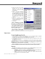
1. Select Configure-Database from the main menu - the warning message shown below
will appear. Click OK to enter the Database Management dialog box.
2
4 3 -T V - 25 - 1 2 G L O I s s u e 3 03 / 0 1 UK
2.
Note the name of the active
database (the one with the
green tick) - in this case "Original Database."
3.
Select a non-active database
(e.g. "test database") and click
on Make Current, (if you only
have a single database in the
list, create a new empty database by clicking on Create, then
select it).
4.
Select the previously active
database ("Original Database")
and click Make Current.
5.
Click Done.
This operation is required
because in TrendManager Pro
V4.9 graphs are stored locally on
the PC on which they were created
- this enables multiple users to
create graphs from the same data,
for instance when the database is
held on a network server.
On selecting a database and
making it Current, any existing
graphs are copied from the database to the new local graph store.
Operation
To start TrendManager Pro V4.9
1.
From Windows™ 3.1 open the TrendManager Pro V4.9 Program Group in Program
Manager, then double-click on the TrendManager Pro V4.9 icon.
2.
From Windows™ 95 or 98 click on the Start button, open the Programs list then select
TrendManager Pro V4.9.
TrendManager Pro V4.9 has a comprehensive on-line Help facility which includes
detailed instructions on how to use TrendManager Pro V4.9, as well as information on
Honeywell recorders. A section on using Help in TrendManager Pro V4.9 is also
included and this is repeated later in this Chapter.
When TrendManager Pro V4.9 is running a Menu bar and a Toolbar are displayed at
the top of the display. A brief description of each of these facilities is given overleaf.
Menu bar
The Menu bar performs in the same way as any standard Windows menu bar. The
TrendManager Pro V4.9 Menu bar contains the following options:
•
Configure - primarily for setting up a Honeywell recorder, but also allows certain TrendManager Pro V4.9 configuration and Printer setups.
•
Graph - from this menu you can open a graph. Once a graph is open, this menu
also allows you to set up and print a graph.
4 3 -T V - 2 5- 1 2 G L O I s s u e 3 0 3/ 01 U K
3
•
Data - from this menu you can either import data from a recorder or export data
to other PC applications.
•
View - from this menu you can enable or disable certain features such as the
Toolbar or Status bar.
•
Help - this menu offers all the Help-related functions.
One other item, Window, is added to the Menu bar when a Graph Window is open. This
is a standard Windows application item.
Toolbar
The Toolbar allows quick operation of certain functions found in the Menu bar. Tool Tips
are given for each icon in the Toolbar - point to an icon with your mouse pointer and a
brief description of that icon will appear.
To operate a Toolbar function click on the corresponding icon.
Help in TrendManager Pro V4.9
1.
Help in TrendManager Pro V4.9 can be used in various ways.
Select Index from the Help drop-down menu and choose the topic on which help is
required.
2.
Click on the Help Icon, then point-and-click on the relevant topic.
3.
Press F1 to call up information on the contents of the currently active window.
There are two types of Help topic:-
•
A jump topic is in green text with a single underline - clicking on this piece of text
will result in a jump to a new topic.
•
A pop-up topic is in green text with a dashed underline - clicking on this piece of
text, displays additional information which will appear, then disappear when
clicked a second time.
Closing Help
Close the Help Window as you would for any Window within the Microsoft Windows
system.
Help Maze
The Help Maze provides an overview of the entire TrendManager Pro V4.9 Help
system - click on a signpost in the Help maze to jump to a topic. The Help Maze will close
down behind you.
Click on this button to enter the Help
Maze
Click on this button to leave the Help Maze.
Remember you can press F1 at any time when TrendManager Pro V4.9 Help is
running for general instructions on using a Windows-based Help system.
4
4 3 -T V - 25 - 1 2 G L O I s s u e 3 03 / 0 1 UK
Chapter 2: Getting the most from
TrendManager Pro V4.9
TrendManager Pro V4.9 includes a range of features designed to make life easier
but which are not always obvious to the first-time user. This document is intended to
help you get straight to those features, improving the functionality of TrendManager
Pro V4.9.
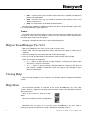
Recorder Configuration
TrendManager Pro V4.9 allows you to set up a Honeywell recorder from the
comfort of your PC. The heart of this facility is the Recorder Configuration Page,
from where you have access to the set-up facilities available on a Honeywell
recorder. The advantage of keyboard and mouse operations makes the entire
process much faster. Once you have selected your set-ups save them to floppy disk
so that you can transfer the set-ups to a Honeywell recorder.
Some of the main features of the Recorder Configuration Page are described
below.
•
Copy Pen set-ups to other pens using the right mouse button - click-anddrag a Pen button over to another pen you want set-up in the same way. This
copies ALL pen set-ups, including Maths Expressions, which means that the
copied pens will display the same data as the original.
•
The amount of recording time with your chosen set-ups is calculated for you
by the Disk Usage Calculator - click on the Disk Use button with the left
mouse button to operate this feature.
•
The simulated display provides you with an instant means of assessing how
your current set-ups will look on a Honeywell display.
•
To save set-ups to disk place the disk in the drive of your PC and click on the
Export button.
See Recorder Configuration Page in the Help facilities.
Importing Data
Having used TrendManager Pro V4.9 to set-up a Honeywell recorder, the next
main function of TrendManager Pro V4.9 is to store your recorded data. Take the
disk from your recorder, place it in the drive of your PC and click on the Import icon.
NB. If you are ever unsure about what an icon does, place the mouse pointer over it
and a "tool tip" will appear, giving a brief description of the icon.
4 3 -T V - 2 5- 1 2 G L O I s s u e 3 0 3/ 01 U K
5
Data is stored under individual "Recorders" on the TrendManager Pro V4.9 database.
It is worth investigating the on-line Help for this subject to fully understand the Import
process.
The main features of the Import Data facility are:
•
The Import Window which provides information on incoming data and shows the
progress of the operation.
•
Automatic creation of new "Recorders" on the database where the data can be
stored according to the ID number and description of the source recorder.
•
Choose whether to include the latest set-ups from the source recorder along with
the imported data.
See Importing Data in the Help facilities.
Graphing
TrendManager Pro V4.9 allows you to prepare the data imported from Honeywell
recorders as a graph. To open a graph click on the Graph icon which displays the Graph
Settings Page. From here select various data sources for your graph. (Data is imported to
each "Recorder" on the TrendManager Pro V4.9 database under the Pen on which it was
recorded - a data source is therefore a particular Pen from any one of the "Recorders" on
the database.)
The main features of the Graph Settings Page are:-
•
"Click-and-drag" a data source (or Pen) to a Graph Area using the left mouse button.
•
Graphs can be split into up to four graph areas, each of which could contain 12
different data sources. A graph area is activated as soon as you "drag" a data
source into it.
•
Remove a data source from the Graph Settings Page by dragging the data source
to the Remove Bin.
•
Select the style in which a data source will be displayed on a graph by doubleclicking on the data source in a Graph Area - this generates the Trace Settings
Page.
Further selection of data for a graph is possible through the Data Locator (see below).
The Data Locator is a tool for selecting various data sources over a specified time
span. Within the Data Locator each data source is represented as a coloured bar which
stretches over the time span during which the data was recorded. Where the data was
recorded over more than one recording session, the bar will be split into sections
representing each session. The Data Locator is used as follows:1. Click on the Enable check box to select a data source.
6
2.
Specify the overall time span by "dragging out" a box to the width you require. Alternatively, use the Zoom buttons to reduce the time span ("In" button), increase the time
span ("Out" button) or return to full width ("All" button).
3.
Move to a particular point in time by "dragging" the scroll bar using the left mouse button
- the centre time of the Data Locator is shown as you move the scroll bar.
4.
Click on a data source with the right mouse button to bring up information on that session such as Start time, Stop time, Logging method used, and Number of readings.
4 3 -T V - 25 - 1 2 G L O I s s u e 3 03 / 0 1 UK
The Data Locator displays the time span and sources of data made available to a graph
(or exported to another application - see Exporting Data overleaf).
Graphs are opened as Graph Windows, and can be moved, re-sized or minimised in
the same way as any standard Windows™ application. Once you have selected the layout
of your graph, it can then be printed or the data shown in the graph can be exported to
another application.
Using the Mouse
•
"Click-and-drag" a box around a section of the graph to “zoom in”, either on the xaxis, or the y-axis, or both.
•
Cancel a "click-and-drag" operation by clicking the right mouse button while the
left button is still held down.
•
Switch between scales for each trace by double-clicking on the scale of a Graph
Area.
•
Double-click on a scale with the right mouse button to return the Graph Area to
full y-axis.
•
Various icons become available in the TrendManager Pro V4.9 toolbar when a
Graph Window is open.
Exporting Data
Data can be exported from TrendManager Pro V4.9 in Comma Separated Variable
(CSV) format to files which can then be imported to other applications on your PC, such
as Microsoft Excel™, Lotus 1-2-3™, and Quattro Pro™.
1.
2.
Data can be exported in two ways:Click on the Export icon to export data selected in the Data Locator (as described in
Graphing in the previous section).
Click on the Export View icon, which exports the data contained in the Graph Window
activated at the time.
Both methods call up the Export Window - here select whether you want to export the
data using the standard or Lotus 1-2-3™ time/date format.
Snap Shot Viewer
This facility allows you to look at Screen Dumps taken from a Honeywell recorder.
(Screen Dumps are instantaneous images of the recorder display captured on disk when
the SHIFT and MODE keys are pressed.)
To use the Snap Shot Viewer, place the disk containing the Screen Dumps in the drive
of your PC and click on the Snap Shot icon. TrendManager Pro V4.9 will automatically
scan the disk and present any detected Screen Dumps as a list on the right side of the
screen. Highlight the selection required by clicking on the relevant item in the list, then
click on View Snapshot. The image will appear on the left side if the screen.
4 3 -T V - 2 5- 1 2 G L O I s s u e 3 0 3/ 01 U K
7
8
4 3 -T V - 25 - 1 2 G L O I s s u e 3 03 / 0 1 UK
Chapter 3: Honeywell
Communications
Introduction
There are two types of RS485 network communications that can be used with
Honeywell recorders for the purposes of downloading data to a host in real time.
Trendbus is a Honeywell protocol that is used in conjunction with the Windowsbased TrendManager Pro V4.9 software. This allows real-time downloading of
data to a host PC which TrendManager Pro V4.9 uses to create real-time graphs
and update records of the set-ups for each recorder in the network. This manual
details the MultiPort Trendbus function where up to 8 communications ports may be
used from one PC running TrendManager Pro V4.9. For single port Trendbus
operation please refer to the Honeywell Comms User Manual (Part number 43TV-25-02).
Modbus™ is an industry standard protocol used in many SCADA packages for
network control. This allows Honeywell recorders to be inserted into existing
networks using Modbus™ or linked directly to a controller over an RS485 link.
Please refer to the Honeywell Comms User Manual (Part number 43-TV-25-02)
for information on Modbus™.
4 3 -T V - 2 5- 1 2 G L O I s s u e 3 0 3/ 01 U K
9
10
4 3 - T V - 2 5- 1 2 G L O I s s u e 3 0 3 / 01 UK
Chapter 4: Trendbus
Introduction
This section is intended for use with Honeywell recorders fitted with a
Trendbus communications card.
Trendbus is an RS485 serial communications protocol developed by Honeywell
enabling 32 recorders to be linked in a network configuration. Each recorder may
download information to a PC. Using TrendManager Pro V4.9, data from selected
pens on any of the networked recorders can be saved in the TrendManager Pro
V4.9 database and displayed as graphs in real time.
This section expains how to install and operate recorders using the Trendbus
communications network. Further instructions are found in the Honeywell User
Manual and the TrendManager Pro V4.9 on-line Help facility and references to
these aids are made in this manual where necessary.
NOTICE
When using Trendbus communications, the recorder date/time is synchronized to
the PC clock which bases all its calculations on the Time Zone currently in use.
To avoid problems, the user MUST ENSURE THAT AUTOMATIC DAYLIGHT
ADJUSTMENT IS TURNED OFF. This will mean that manual time adjustment
forwards or backwards an hour will be necessary in order that the time of the
recorders be the same as the local time. Some users may not want to allow for
daylight saving, and log all data to GMT or their local standard time at a fixed offset
from GMT. There are no difficulties associated with this mode of operation.
Recorders which are not connected to Trendbus will have to be adjusted manually
for daylight saving. The data imported into TrendManager Pro V4.9 will always be
graphed at the time of the data, with no allowances for daylight saving being made,
e.g. data recorded at 10 a.m. will be graphed on TrendManager Pro V4.9 at 10
a.m. whether or not the PC is an hour ahead. If users wish to combine their data
from different processes on one graph, they must ensure that all recorders are
synchronized.
4 3 -T V - 2 5- 1 2 G L O I s s u e 3 0 3/ 01 U K
11
Specifications
Recorders
Any model of Honeywell V5 Recorder can be installed in a Trendbus network.
The recorder must also be fitted with an RS485 card.
PC requirements
An RS485 card or an RS232-485 converter is required. (For example, a Westermo MA42 fitted directly to the RS232 serial comms port of your PC would be sufficient.) Any
converter or card must be capable of half-duplex operation using RTS control.
Your PC must be running Windows™ 95, 98 or NT - Windows™ 3.1 cannot support
Trendbus.
The Trendbus communications configuration is included in TrendManager Pro V4.9,
and as such your PC must be of the standard specified in the TrendManager Pro V4.9
Installation Instructions.
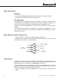
Installation and Connection
Trendbus networks are subject to standard RS485 specifications.
Connection to the network is made via the 9-way D-type connector on the rear panel of
the recorder. The pin-outs are as shown below:
1
6
Not
Connected
7
8
9
2
3
0 Volts (isolated)
RX/TX +ve
RX/TX -ve
4
5
Not
Connected
Operation
Ensure that the Comms facility is enabled on each recorder in the network and that all
recorders are set to the same baud rate. To do this select the Comms option in the
Special Setups menu as described in the Honeywell User Manual.
The remainder of the set-up procedure is performed in TrendManager Pro V4.9. Full
information is contained in the TrendManager Pro V4.9 on-line Help facility, but a brief
sequence of actions is given below for ease of reference.
1.
12
From the Configure menu in TrendManager Pro V4.9, select the Communications
option.
4 3 - T V - 2 5- 1 2 G L O I s s u e 3 0 3 / 01 UK
2.
From the Trendbus dialog box, check the Enable Trendbus box and select the Comms
port on your PC to which the network is connected. Select the same baud rate as
selected on each of your recorders in the network.
3.
Click on OK and the Communications Status window will appear. (You can remove this
window by clicking on the Close button, open it again by selecting Communications Status from the View menu.)
4.
Each recorder on the network should have a corresponding recorder on the TrendManager Pro V4.9 database. To check this select Recorders from the Configure menu - a
list will appear with all the recorders on the database. The ID numbers of each of these
recorders should be unique and should correspond to the ID numbers of the recorders
in the network. (If you cannot find a networked recorder on the database, you may need
to create one as described in the TrendManager Pro V4.9 Help section on Creating a
New Recorder.)
5.
For each networked recorder on the database you must go to the Recorder Configuration page and select System. In the Comms section of the System settings ensure that
the Enable Trendbus for this Recorder check box is ticked.
6.
For each individual pen required for the network, go into the Comms section of the Pen
Setups page. From there tick the Comms Pen Enable check box and select the logging
method and speed for data from that Pen to be downloaded onto the network.
7.
When the set-ups are complete, click on OK in the Recorder Configuration page and
that recorder will be added to the Communications Status window. Data will immediately
be downloaded from the selected pens on that recorder to the TrendManager Pro V4.9
database.
With the recorders on the network being successfully linked to TrendManager Pro
V4.9, saved information may be displayed in a graph. Create a graph in the normal way
and select the relevant pen either from the Data Locator or by adding a data source in the
Graph Settings page. All the graphing functions are available and data transferred via
both Trendbus and floppy disk can be presented on a graph. When selecting a pen as a
data source for a graph, the means by which the data for that pen was acquired is shown
by the following symbols:Data acquired from a Pen via Trendbus
Data transferred to TrendManager Pro V4.9 via floppy disk
As data is transferred to a graph from networked recorders, the traces will eventually
reach the edge of the graph. If you select the Auto Scrolling option from the
TrendManager Pro V4.9 toolbar, the graph will be redrawn with the latest data when the
edge of the graph is reached.
4 3 -T V - 2 5- 1 2 G L O I s s u e 3 0 3/ 01 U K
13
Important points about Trendbus
Purpose
Trendbus is designed to allow the user to receive data from remote recorders, without
having to retrieve the disk from the unit. It is not a substitute for recording data onto floppy
disk, which can be done at faster logging rates and with less risk of interruption.
Functions
TrendManager Pro V4.9 uses Trendbus to perform the following functions:-
•
•
Retrieval of the current recorder set-up.
•
Time synchronisation of networked recorders.
Retrieval of real-time data from individual channels on networked recorders at
independent sampling rates and methods.
Setups can not be transferred to a recorder using Trendbus.
Data acquisition
Data acquired using Trendbus is stored in a different location on the TrendManager
Pro V4.9 database from data transferred via floppy disk. The fastest logging rate is 1
second/log and data retrieval can be interrupted during TrendManager Pro V4.9
operations. For this reason Max-Min logging method is recommended, as the recorder
will store the maximum and minimum readings obtained during the interruption and pass
those readings to TrendManager Pro V4.9 when communications are resumed.
The Communications Status window lists all the networked recorders and reports if
there is an error or interruption in data transfer between recorder and TrendManager Pro
V4.9.
For further information consult the on-line Help facility in TrendManager Pro V4.9,
which gives comprehensive details on Communications set-ups, operations and features.
14
4 3 - T V - 2 5- 1 2 G L O I s s u e 3 0 3 / 01 UK
Chapter 5: Trendbus Troubleshooter
Please refer to Appendix A for Westermo MA-42 configuration.
Follow these instructions to eliminate any Trendbus problems:
RS485 to RS232 converter
1.
Ensure that the PC is connected to the bus via the specified RS485 to RS232
converter, and that the converter is configured as follows:
•
•
•
•
RX-Line Terminator IN.
Receive Echo OFF.
Transmit Enable RTS.
Links to connect the converter for Half-Duplex operation, [i.e. TX(A) to
RX(A) and TX(B) to RX(B)].
2.
Check that the power supply is connected and turned on!
3.
Ensure that the recorders are correctly connected to the bus.
Recorder Configuration
1.
Ensure that each recorder is configured for Trendbus as follows:
•
•
2.
In the Factory Hardware options, ensure RS485 TMP Comms is selected.
In the Comms settings (Special Set-up menu) check that the baud rate is
set correctly.
Ensure that the recorder has the correct Unit ID Number, and that it is different on
each recorder.
TrendManager Pro V4.9 Configuration
1.
Ensure that each recorder required to communicate using Trendbus is enabled to
do so in the System settings for that recorder.
2.
Ensure that one or more pens are configured to receive Comms data in the Pen
settings for that pen.
3.
From the Configure Communications option, enable Trendbus and check that the
baud rate is set to match the recorders on the bus, and that the Comms port is
correct.
4 3 -T V - 2 5- 1 2 G L O I s s u e 3 0 3/ 01 U K
15
The Communications Status window will give the status for each recorder. The values
displayed and their meanings are as shown below.
Mode
Description
Initialising
Trendbus is being configured.
TrendManager Pro V4.9 is attempting to download set-up information from the
Downloading
recorder.
Real-Time
TrendManager Pro V4.9 will request real-time data when required.
In Set-Up
The user has entered Set-Up on the recorder. During this time, no data is logged for the
recorder, and once the user exits Set-Up the mode will change to “Downloading”.
Configuration
error
Disabled
Waiting
The pens selected for Comms do not correspond with the pens enabled on the recorder.
A recorder has been removed from Comms operations.
Occurs briefly at Start-Up and if the user enters Set-Up on the recorder.
(blank)
TrendManager Pro V4.9 is retrying the operation.
TrendManager Pro V4.9 received nothing from the recorder. Work through the above
No Reply
checklist to ensure configuration is correct. If all is OK, then your PC is unsuitable for
Trendbus operations. (See minimum PC specification)
TrendManager Pro V4.9 received a reply from the recorder, but it was corrupt. If the
RX Error
error persists you may have a faulty connection on two recorders with the same ID Number
(see note below.)
TrendManager Pro V4.9 tried unsuccessfully to communicate with the recorder via
Trendbus. If this persists check that you have selected a valid comms port on your PC. If
this is OK then your PC is unsuitable for Trendbus operations. (See minimum PC
specification)
A general comms error has occurred. Your PC is unsuitable for Trendbus operations. (See
minimum PC specification)
Trendbus has received real-time data from the recorder. Trendbus is working correctly Congratulations!
Trendbus has received real-time data but it arrived later than expected. If this is a common
occurrence then the system is too heavily loaded. The user should reduce the log rate for
the pens of the recorder(s) in question.
TX Error
Error
Talking
Talking *
Continuous RX Errors
If you are frequently getting an RX Error message in the Communications Status
window, and you have checked that
•
•
There is no faulty connection in the RS485 wiring.
There are no recorders in the network with the same ID number. You should try
amending the RX timeout in the TMP.INI file. To do this use a text editing package, such as Windows™ Notepad, to open the file. In the [comms] section of the
file you will find a line Timeout = 100. Change the value from 100 to 200, then
save and close the file.
If you are still getting frequent RX Error messages, try changing the Baud rate of the
network, first to 19200, then, to 9600. (Change the baud rate on the recorders also.)
16
4 3 - T V - 2 5- 1 2 G L O I s s u e 3 0 3 / 01 UK
Chapter 6: Modbus™
Introduction
Controllers using Modbus™ communicate using a master-slave technique, in
which only one device (the master) can initiate transactions (called "queries"). The
other devices (the slaves) respond by supplying the requested data to the master.
Honeywell recorders play the role of a slave in a Modbus™ network, and when
addressed by a master will return a message (called a "response") to the query.
The Modbus™ protocol establishes the format for the master's query by placing
into it the device address, a function code defining the requested action, any data
to be sent, and an error-checking field. The slave's response message is also
constructed using Modbus™ protocol. If an error occurs in receipt of the message,
the slave will construct an error message and send it as its response. Modbus™ is
a well-documented industry standard and it is not the purpose of this manual to go
into detail on how Modbus™ operates. Documents such as the Modicon Modbus™
Protocol Reference Guide provide in-depth information on Modbus. Certain
aspects of using Modbus communications with a Honeywell recorder are peculiar
to the product, and this section of the manual will deal with these aspects.
Specifications and Protocols
Recorder
To connect a Honeywell recorder to a Modbus™ network the recorder must be
fitted with a Honeywell Modbus™ card. This card is terminated in a 9-way D-type
socket which provides connection for serial RS485 Modbus™ communications.
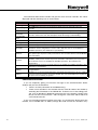
Master
Honeywell recorders incorporated in serial Modbus™ networks require the
RTU mode of message framing. The following function codes are supported by
Honeywell recorders (refer to Modicon Modbus Protocol Reference Guide for
further information).
4 3 -T V - 2 5- 1 2 G L O I s s u e 3 0 3/ 01 U K
17
01
Read output coil status
02
Read input status
03
Read holding registers
04
Read input registers
05
06
Force single output coil
Pre-set single holding register
07
Read exception status
08
Diagnostics
15
Force multiple coils
16
Pre-set multiple registers
Reads the ON/OFF status of discrete outputs (0X registers) in the
slave.
Reads the ON/OFF status of discrete inputs (1X registers) in the
slave
Reads the binary contents of holding registers (4X registers) in the
slave.
Reads the binary contents of input registers (3X registers) in the
slave.
Forces a single coil (0X register) to either ON or OFF.
Pre-sets a value into a single holding register (4X register)
Reads the contents of eight Exception Status coils within the slave
controller. Certain coils have pre-defined assignments in the slave,
others can be programmed by the user to hold information about the
slave's status.
Provides a series of tests for checking the communications system
between master and slave, or for checking for various internal error
conditions within the slave.
Forces each coil (0X register) in a sequence of coils to either ON or
OFF.
re-sets values into a sequence of holding registers (4X registers).
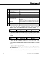
The function codes above are applicable to particular registers. The individual
Modbus™ registers used on Honeywell recorders are described below. For ease of
reference, a concise version of the information below is included in Appendix B.
Modbus™Start Reg
Class
Number of Points
Input/Output
Comments
0:0001
Digital
16 bits to 0:0016
Output
Set relay outputs
Relay output override. The state of relay outputs on a recorder can be set from the
Modbus™ master. Relay override must be enabled in registers 0:0009 to 0:0016 for
Relays O1 to O8 respectively, where 0 = disabled and 1 = enabled. The relays are then
set in registers 0:0001 to 0:0008 for Relays O1 to O8 respectively, where 0 = open and 1
= closed.
Modbus™Start Reg
Class
Number of Points
Input/Output
Comments
1:0001
Digital
24 bits to 1:0024
Input
Read digitals
Digitals. (Bits 1:0001 to 1:0016 can be addressed as a 16 bit word at 3:0001, and bits
1:0017 to 1:0032 as a 16 bit word at 3:0002.)
The state of the contact between the NO and C terminals of a digital are read from
registers 1:0001 to 1:0008 for channels O1/I8 to O8/I1 respectively, where 1 = closed
contact.
Registers 1:0009 to 1:0016 are reserved.
Registers 1:0017 to 1:0024 are used specifically for the state of Digital Inputs 8 to 1
respectively where 1=externally applied closed contact. (Typically DI3 - DI8 are not used
and should never be 1.)
Registers 1:0025 to 1:0032 are used specifically for the state of Relay Outputs 1 to 8,
where 1 = contact closed internally or by the Modbus™ master override.
18
4 3 - T V - 2 5- 1 2 G L O I s s u e 3 0 3 / 01 UK
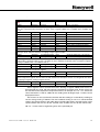
.
Modbus™Start
Reg
Class
Number of Points
Input/Output
Comments
3:0033
Analogue
9 Floats
Input
Pen 1 to 9 (Array)
The analogue value of each Pen is stored in two register locations, (where each register is two bytes), as a floattype value, which is therefore four bytes, (so Pen 1 starts at register 3:0033, Pen 2 at 3:0035, Pen 3 at 3:0037, and
so on).
3:0257
String
20 Char
Input
Pen1, Units, Scale Factor, Name
3:0267
String
20 Char
Input
Pen2, Units, Scale Factor, Name
3:0277
String
20 Char
Input
Pen3, Units, Scale Factor, Name
3:0287
String
20 Char
Input
Pen4, Units, Scale Factor, Name
3:0297
String
20 Char
Input
Pen5, Units, Scale Factor, Name
3:0307
String
20 Char
Input
Pen6, Units, Scale Factor, Name
3:0317
String
20 Char
Input
Pen7, Units, Scale Factor, Name
3:0327
String
20 Char
Input
Pen8, Units, Scale Factor, Name
3:0337
String
20 Char
Input
Pen9, Units, Scale Factor, Name
The associated information with each Pen value (i.e. the Pen units, scale factor and name) are held as strings of 20
char-type values, with two characters occupying a single register location.
3:0347
Analogue
9 unsigned integers Input
Scale top value pens 1 to 9 (array)
3:0356
Analogue
9 unsigned integers Input
Scale bottom value pens 1 to 9 (array)
These registers hold the scale information for each Pen. The top values are held as 9 unsigned integers (one in
each location) starting at 3:0347 for Pen 1 to 3:0355 for pen 9. Similarly, the bottom values are held in 9 registers
starting at 3:0356 for Pen 1 to 3:0364 for Pen 9.
3:1281
Analogue
1 unsigned long
Input
Serial number (value 0..999999)
3:1283
Analogue
1 unsigned integer
Input
ID number (value 0..9999)
The recorder serial and ID number are held in the above locations. The serial number is a long-type integer and
therefore needs to be stored in two registers.
3:1284
String
6 Char
Input
Unit Name
3:1287
String
20 Char
Input
Unit Description
The recorder name and description are held in these registers. The unit name consists of a string of 6 char values
which occupy three registers from 3:1284 to 3:1286, and the unit description consists of a string of 20 char values
occupying ten registers starting at register 3:1287.
4:0033
Analogue
8 Floats
Output
C1 to c8 (array)
4:0257
String
18 Char
Output
Time. “hh:mm:ss mm/dd/yy”
These registers can be set from the master. Starting at register 4:0033, float values can
be entered for C1 to C8, with two registers required for each float value. These values can
be read into maths expressions for particular Pens, for example P1 = A1 + C1, where the
value entered for C1 will be added to the reading from Analogue Input 1 and the result
displayed on Pen 1.
The master can also synchronise the time and date setting on a recorder by sending an
18 char string starting at 4:0257. The time and date setting is sent as a null-terminated
string in the format shown in the table above, including the colons, forward slashes and a
space between the last char for the seconds value and the first char for the month value.
NB. C1 - C8 are taken in engineering units of the specified pen.
4 3 -T V - 2 5- 1 2 G L O I s s u e 3 0 3/ 01 U K
19
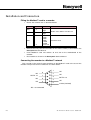
Installation and Connection
Fitting the Modbus™ card to a recorder
•
Ensure hex switches are as described below.
Switch
Position
SW1
0-F
SW2
0-F
SW3
0
1
2
3
4
5
6-F
Value
High hex
digit
Low hex
digit
1200
2400
4800
9600
19200
38400
Reserved
Comment
Modbus slave address from 00 to FF
Default baud rate
•
Remove the rear panel and and slide out the PCB assembly as described in the
Honeywell Service Manual.
•
Insert Modbus™ card into sockets J9 and J18 on the motherboard of the
recorder.
•
Re-assemble as shown in the Honeywell Service Manual.
Connecting the recorder to a Modbus™ network
This is made via the 9-way D-type connector on the Modbus™ card at the rear of the
recorder. The pin-outs for this connector are shown below:
1
NC
6
RX/TX -ve
7
NC
8
NC
9
2
3
4
5
NC
NC
RX/TX +ve
NC
0 Volts (isolated)
NC - not connected
20
4 3 - T V - 2 5- 1 2 G L O I s s u e 3 0 3 / 01 UK
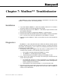
Chapter 7: Modbus™ Troubleshooter
The following is a list of checks that should be performed in the event of the
Modbus™ communications not working correctly.
Installation
1.
If you have fitted the Modbus™ card to the recorder, check that it is inserted in
the correct sockets on the motherboard of the recorder.
2.
Check that the pin-outs of the Modbus™ card 9-Way D type connector match
your network connectors.
3.
Check that the recorder is configured for Modbus™ communications.
4.
Check that the baud rate selection switch and slave address switches on the Modbus™ card are set to match the requirements of your Modbus™ network.
5.
Check that no other Modbus™ device on the network has the same hexadecimal
address.
Diagnostics
The Modbus™ card is fitted with RX and TX LEDs that indicate whether queries
are being received from the master and whether responses are being sent back by
the recorder. The following is a list of checks that should be performed in the event
of various states of these LEDs.
1. RX flashing, TX off. This suggests that the master is sending queries to the
recorder but the recorder is not responding. This may be due to:
•
•
•
2.
3.
The recorder not being configured for Modbus™ comms.
The Modbus™ card not being correctly installed.
Incorrect baud rate and address settings on the Modbus™ card.
RX off, TX off. This suggests no messages are reaching the recorder from the
master. This may be due to:
•
The RS232-485 converter (if used) not powered up or connected to the
master/network incorrectly (e.g. wrong COM port). Check LED diagnostics
(where available) on the converter.
•
Incompatible pin-outs between Modbus™ card and network cable.
RX and TX flashing, incorrect data being returned. This may be due to incorrect
register settings specified in the queries from the master (refer to Modbus™
memory map in Appendix B).
4 3 -T V - 2 5- 1 2 G L O I s s u e 3 0 3/ 01 U K
21
22
4 3 - T V - 2 5- 1 2 G L O I s s u e 3 0 3 / 01 UK
Appendix A - Comms
Interface
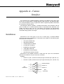
For connecting of an RS485 Trendbus network to the RS232 serial comms port
on your PC, you will require a suitable RS232-to-485 converter. The Westermo MA42 is recommended for such an application and this appendix provides information
on using this particular device.
The Westermo MA-42 provides a reliable link between your computer and the
plant. The MA-42 is an external device which is separately mains powered - this
avoids the need to open your PC. The MA-42 also provides full opto-isolation
between the remote field bus and your PC thereby offering full protection from
unwanted voltage spikes and surges.
Installation
Connection to the serial port of your PC is made using a standard RS232
extension lead to the V.24/RS-232-C connection on the MA-42. The following pins
are used in this connection:2TD (Transmitted Data)
•
•
•
•
•
•
•
•
3RD (Received Data)
4-RTS (Request To Send)
5-CTS (Clear To Send)
6-DSR (Data Set Ready)
7-SG (Signal Ground)
8-DCD (Data Carrier Detect)
20-DTR (Data Terminal Ready)
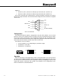
Connection to the RS485 network is made from the 5-pin Line Connection
terminal on the MA-42. The pins used are as follows:Trendbus
Terminal 3 ( A/A' ) connects to 9-Way D type connector pin 3 (RX /TX -ve)
•
•
Terminal 4 ( B/B' ) connects to 9-way D type connector pin 2 (RX /TX +ve)
1
6
Not
Connected
7
8
9
4 3 -T V - 2 5- 1 2 G L O I s s u e 3 0 3/ 01 U K
2
3
0 Volts (isolated)
RX/TX +ve
RX/TX -ve
4
5
Not
Connected
23
Modbus™
•
•
Terminal 3 ( A/A' ) connects to 9-Way D type connector pin 7 (RX/TX +ve)
Terminal 4 ( B/B' ) connects to 9-Way D type connector pin 3 (RX/TX -ve)
Pins on this connector are numbered from 1 nearest the Mains connector to 5 nearest
the 25-way D-type connector. The screw-terminal mating-half of the connector is supplied
with the unit.
1
6
NC
RX/TX +ve
7
NC
8
NC
9
NC
2
NC
3
RX/TX -ve
4
NC
5
0 Volts (isolated)
NC - not connected
Configuration
The Westermo MA-42 requires configuration using the DIP switches on the circuit
board. To access the switches ensure all leads to the unit are disconnected, then open
the case by placing and twisting a flat screwdriver between the top and bottom of the
case at the rear of the unit on one corner. Repeat this operation on the other rear corner,
then on the front two corners until the top of the case falls free.
The switches are set as follows:-
•
•
•
S1-set to 230 V or 115 V depending on your Mains supply
S2-switches 1 and 4 ON
S3-switches 2, 5 and 6 ON
S3
230
S1
2
1
34
5 6
ON
OFF
1
S2
4
23
ON
5 6
OFF
Operation
With the connections and configuration made as described above, the unit will convert
all signals on the RS485 Trendbus network into the RS232 format required by the serial
port of your PC. Ensure that the unit is powered correctly, TrendManager Pro V4.9 will
control the transfer of data over the network. Any problems can be diagnosed by the
LEDs on the MA-42 as described below.
24
4 3 -T V - 25 - 1 2 G L O I s s u e 3 03 / 0 1 UK
Diagnostics
The LEDs on the front panel of the MA-42 provide the following:
LED
PWR
RD
DCD
CTS
RTS
TD
4 3 -T V - 2 5- 1 2 G L O I s s u e 3 0 3/ 01 U K
Indication when lit
Power to the unit is correctly supplied
Data is being received on the RS485
interface
Simulated carrier controlled by RTS
Follows RTS
RS485 transmitter is activated
Data is being received on the RS232
interface
25
26
4 3 -T V - 25 - 1 2 G L O I s s u e 3 03 / 0 1 UK
Appendix B - Modbus™
Memory Map
Valid function codes:
01 - Read output coil status
02 - Read input status
03 - Read holding registers
04 - Read input registers
05 - Force single output coil
06 - Pre-set single holding register
07 - Read exception status
08 - Diagnostics
15 - Force multiple coils
16 - Pre-set multiple registers
Modbus™
Start Reg
Class
Number of Points
Input/Output
Comment
3:0033
3:0257
3:0267
3:02757
3:0287
3:0297
3:0307
3:0317
3:0327
3:0337
3:03407
3:0356
3:1281
3:1283
3:1284
3:1287
4:0033
4:0257
Analogue
9 Floats
Input
Pen 1 to Pen 9 (array)
String
20 Char
Input
Pen1, Units, Scale Factor, Name
String
20 Char
Input
Pen2, Units, Scale Factor, Name
String
20 Char
Input
Pen3, Units, Scale Factor, Name
String
20 Char
Input
Pen4, Units, Scale Factor, Name
String
20 Char
Input
Pen5, Units, Scale Factor, Name
String
20 Char
Input
Pen6, Units, Scale Factor, Name
String
20 Char
Input
Pen7, Units, Scale Factor, Name
String
20 Char
Input
Pen8, Units, Scale Factor, Name
String
20 Char
Input
Pen9, Units, Scale Factor, Name
Analogue
9 signed integer
Input
Scale hi for Pen 1 to Pen 9 (array)
Analogue
9 signed integer
Input
Scale low for Pen 1 to Pen 9 (array)
Analogue
1 unsigned long
Input
Serial number value 0..999999
Analogue
1 unsigned integer
Input
ID number value 0..9999
String
6 Char String
Input
Unit Name
String
20 Char String
Input
Unit Description
Analogue
8 Floats
Output
C1 to C8 (array)
String
18 Char String
Output
Time “hh:mm:ss mm/dd//yy”
1:0001
Digital
24 bits > 1:0024
Input
0:0001
Digital
16 bits > 0:0016
Output
4 3 -T V - 2 5- 1 2 G L O I s s u e 3 0 3/ 01 U K
See “Note 1. Digital
Inputs.” on page 28.
See “Note 2. Relay Output
Overrides.” on page 28.
27
Note 1. Digital Inputs.
(Bits 1:0001 to 1:0016 can be addressed as a 16 bit word at 3:0001, and 1:0017 to
1:0032 as a 16 bit word at 3:0002)
1:0001 to 1:0008Contact O1/I8 to Contact O8/I1 1 if contact closed internally (Ox) or
externally (Ix).
1:0009 to 1:0016Reserved.
1:0017 to 1:0024Digital Input I8 to Digital Input I1 1 only if contact closed externally.
(Unused inputs typically I3..I8 never 1)
1:0025 to 1:0032Relay O1 to Relay O8 1 only if contact closed by internal relay, or
Modbus™ override. (Non existent relays never 1.)
Note 2. Relay Output Overrides.
0:0001 to 0:0008Relay O1 to Relay O8 Override 0 = Open, 1 = Closed. State of relays
O1..O8 only takes effect if corresponding relay override enable bit set too. Gives remote
override of relays from Modbus™ master.
0:0009 to 0:0016Relay O1 to Relay O8 Override enable 0 = Disabled, 1 = Enabled.
Override enable (normally 0).
NB. Both relay override and override enable can be addressed as a 16 bit value at
address 4:0001.
28
4 3 -T V - 25 - 1 2 G L O I s s u e 3 03 / 0 1 UK
Index
A
E
Analogue Input .......................................................19
Auto Scrolling ..........................................................13
Export ............................................................................ 5
Export Icon .................................................................7
Export View Icon .....................................................7
Export Window .........................................................7
B
Baud Rate
............................................................16, 21
C
Comma Separated Variable ...............................7
Comms Port ..............................................................13
Communications Status ................................13, 14
Configuration Error .............................................16
Configure Communications .............................15
Configure Menu .....................................................13
Current Recorder Set-up ....................................14
D
Data Locator .........................................................6, 7
Database Management .........................................2
Daylight Saving ......................................................11
Diagnostics ...............................................................18
Digitals .......................................................................18
Disabled .....................................................................16
Disk Usage Calculator .........................................5
Disk Use .......................................................................5
Downloading ...........................................................16
4 3 -T V - 2 5- 1 2 G L O I s s u e 3 0 3/ 01 U K
F
Factory Hardware Options ............................... 15
Force Multiple Coils ............................................18
Force Single Output Coil ...................................18
Function Codes ......................................................18
Functionality .............................................................5
G
Graph Area .................................................................6
Graph Icon ..................................................................6
Graph Settings ........................................................ 13
Graph Settings Page ..............................................6
Graph Window ...................................................... 6, 7
Graphs ..........................................................................3
H
Half-Duplex ..............................................................15
Help .............................................................................. 11
Help Maze ...................................................................4
Hexadecimal Address ..........................................21
29
I
ID Number ............................................................ 6, 13
Import ........................................................................... 5
Import Data ............................................................... 5
Import Window ......................................................... 6
In Set-Up ................................................................... 16
Initialising ................................................................ 16
J
Jump Topic
.................................................................. 4
L
LED Diagnostics ................................................... 21
Logging Rates ......................................................... 14
M
Master-Slave Technique ..................................... 17
Maths Expressions .................................................. 5
Max-Min Logging Method ............................... 14
Menu Bar .................................................................... 3
Minimum Specification ........................................ 1
Modicon Modbus Protocol ............................... 17
Multiple Users .......................................................... 3
N
Network Server ........................................................ 3
No Reply .................................................................... 16
P
Pen Enable ................................................................ 13
Pen Setups ............................................................. 5, 13
Pentium Processor .................................................. 1
30
Pop-up Topic .............................................................. 4
Pre-set Multiple Registers ................................ 18
Pre-set Single Holding Register .................... 18
Protocol Reference Guide ................................. 17
R
RAM ............................................................................... 1
Read Exception Status ........................................ 18
Read Holding Registers ..................................... 18
Read Input Registers ........................................... 18
Read Input Status .................................................. 18
Read Output Coil Status .................................... 18
Real-Time .................................................................. 16
Real-Time Data ...................................................... 14
Recorder Configuration ..................................... 13
Recorder Configuration Page ........................... 5
Registers .............................................................. 18, 19
Relay Outputs ......................................................... 18
Relay Override ....................................................... 18
RS232 .............................................................. 12, 15, 23
RS485 .................................................... 1, 11, 12, 15, 23
RS485 to RS232 Converter .............................. 15
RTU Mode ................................................................ 17
RX Error .................................................................... 16
RX-Line Terminator ............................................. 15
S
Screen Dumps ........................................................... 7
Snap Shot Icon ......................................................... 7
Snap Shot Viewer .................................................... 7
Special Set-up Menu ............................................ 15
System Settings ....................................................... 15
T
Talking ........................................................................ 16
Talking * .................................................................... 16
Time Synchronisation .......................................... 14
Tool Tips ...................................................................... 4
Toolbar ..................................................................... 3, 4
Trace Settings Page ................................................ 6
Trendbus .................................................................... 11
4 3 -T V - 25 - 1 2 G L O I s s u e 3 03 / 0 1 UK
Trendbus Problems ...............................................15
Trendpro .......................................................................2
TX Error .....................................................................16
U
Unit ID Number .....................................................15
Valid Function Codes ..........................................27
VWXYZ
Waiting ........................................................................16
Warning Message ....................................................2
Westermo .......................................................12, 23, 24
4 3 -T V - 2 5- 1 2 G L O I s s u e 3 0 3/ 01 U K
31
32
4 3 -T V - 25 - 1 2 G L O I s s u e 3 03 / 0 1 UK
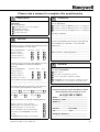
Please take a moment to complete this questionnaire
Reputation
1
3
Products
How do you perceive our range of products?
How would you rate the reputation of
Honeywell?
Tick as appropriate
Tick as appropriate
Products offered are better than those of competitors
A very reputable, successful company
A reputable company
Products offered are worse than those of competitors
A disreputable company
Products offered are the same as those of competitors
No views either way
2
Service
How do you rate or perceive the following service
levels provided by our sales staff?
Tick as appropriate
Excellent
Good
Fair
Response speed
Quality of response
Follow up response
Overall level of service
How do you rate or perceive the following service
levels provided by our Technical Support
Service?
Tick as appropriate
Excellent
Good
Fair
Response speed
Any other comments
..............................................................................
..............................................................................
..............................................................................
Are there any products that we do not provide that
you would like us to provide - or any we could
improve on?
..............................................................................
..............................................................................
..............................................................................
Improvements to existing products..........................
..............................................................................
..............................................................................
..............................................................................
4
General
If you are an existing or new customer, what made
you choose Honeywell?
Only on price
Quality of response
Price plus a combination of factors
Follow up response
Overall level of service
Prefer to deal with a reputable company
How could our service be improved upon?
..........................................................................
..........................................................................
Honeywell offers more than the competition in terms
of ’added value’ over and above the product itself
How many times do you receive a visit from one
of our Sales representatives? Visits every:
Thank you for completing this questionnaire.
1-3 months
Please fill out your name and address below.
Photo copy this form and Fax to us on
3-6 months
6-12 months
How does that compare to our competitors?
More
Less
The same
+44 (0)1202 476501
Name .....................................................
Score on a level of 1-10, with 10 being the best
Company name ......................................
Address .................................................
Quality of manuals / sales literature
Administration / documentation and letters
Technical expertise of our sales staff
Sales staff ability to give informed advice
...............................................................
...............................................................
County................. Postcode...................
The quality of the Honeywell sales team.
Tel:........................ Fax..........................
Pricing
Company business ................................
Honeywell understanding of your industry.
...............................................................
43-TV-25-12 GLO Issue 3 03/01 UK
33
Warranty/Remedy
Sales and Service
Honeywell warrants goods of its manufacture as being free of
defective material and faulty workmanship. Contact your local sales
office for warranty information. If warranted goods are returned to
Honeywell during that period of coverage, Honeywell will repair or
replace without charge those items it finds defective. The foregoing
is Buyer’s sole remedy and is in lieu of all other warranties,
expressed or implied, including those of merchantability and
fitness for a particular purpose.
While we provide application assistance, personally, through our
literature and the Honeywell web site, it is up to the customer to
determine the suitability of the product in the application.
Honeywell serves its customers through a worldwide network of
sales offices and distributors. For application assistance, current
specifications, pricing or name of the nearest Authorised Distributor,
contact your local sales office or:
INTERNET: www.honeywell.com/sensing
Specifications may change at any time without notice. The information we supply is believed to be accurate and reliable as of this
printing. However, we assume no responsibility for its use.
ARGENTINA
BULGARIA
GERMANY
NORWAY
HONEYWELL S.A.I.C.
BELGRANO 1156
BUENOS AIRES
ARGENTINA
Tel. : 54 1 383 9290
HONEYWELL EOOD
14, Iskarsko Chausse
POB 79
BG- 1592 Sofia
BULGARIA
Tel : 359-791512/
794027/ 792198
HONEYWELL AG
Kaiserleistrasse 39
D-63067 OFFENBACH
GERMANY
Tel. : 49 69 80 64444
HONEYWELL A/S
Askerveien 61
PO Box 263
N-1371 ASKER
NORWAY
Tel. : 47 66 76 20 00
CANADA
HONEYWELL Kft
Gogol u 13
H-1133 BUDAPEST
HUNGARY
Tel. : 36 1 451 43 00
ASIA PACIFIC
HONEYWELL ASIA
PACIFIC Inc.
Room 3213-3225
Sun Kung Kai Centre
N° 30 Harbour Road
WANCHAI
HONG KONG
Tel. : 852 829 82 98
AUSTRALIA
HONEYWELL LIMITED
5 Thomas Holt Drive
North Ryde Sydney
NSW AUSTRALIA 2113
Tel. : 61 2 353 7000
AUSTRIA
HONEYWELL AUSTRIA
G.m.b.H.
Handelskai 388
A1020 VIENNA
AUSTRIA
Tel. : 43 1 727 800
BELGIUM
HONEYWELL S.A.
3 Avenue de Bourget
B-1140 BRUSSELS
BELGIUM
Tel. : 32 2 728 27 11
BRAZIL
HONEYWELL DO BRAZIL AND CIA
Rua Jose Alves Da
Chunha
Lima 172
BUTANTA
05360.050 SAO PAULO
SP
BRAZIL
Tel. : 55 11 819 3755
HONEYWELL LIMITED
THE HONEYWELL
CENTRE
529 Mc Nicoll Avenue
M2H 2C9 NORTH YORK,
ONTARIO
CANADA
Tel. : 416 502 5200
CZECH
REPUBLIC
HONEYWELL, Spol.s.r.o.
Budejovicka 1
140 21 Prague 4
Czech Republic
Tel. : 42 2 6112 3434
DENMARK
HONEYWELL A/S
Automatikvej 1
DK 2860 Soeborg
DENMARK
Tel. : 45 39 55 56 58
FINLAND
HONEYWELL OY
Ruukintie 8
FIN-02320 ESPOO 32
FINLAND
Tel. : 358 0 3480101
FRANCE
HONEYWELL S.A.
Bâtiment « le Mercury »
Parc Technologique de St
Aubin
Route de l’Orme
(CD 128)
91190 SAINT-AUBIN
FRANCE
Tel. from France:
01 60 19 80 00
From other countries:
33 1 60 19 80 00
HUNGARY
POLAND
HONEYWELL Sp.z.o.o
UI Domainewksa 41
02-672 WARSAW
POLAND
Tel. : 48 22 606 09 00
ICELAND
HONEYWELL
Hataekni .hf
Armuli 26
PO Box 8336
128 reykjavik
Iceland
Tel : 354 588 5000
PORTUGAL
HONEYWELL
PORTUGAL LDA
Edificio Suecia II
Av. do Forte nr 3 - Piso 3
2795 CARNAXIDE
PORTUGAL
Tel. : 351 1 424 50 00
ITALY
HONEYWELL S.p.A.
Via P. Gobetti, 2/b
20063 Cernusco Sul
Naviglio
ITALY
Tel. : 39 02 92146 1
MEXICO
HONEYWELL S.A. DE
CV
AV. CONSTITUYENTES
900
COL. LOMAS ALTAS
11950 MEXICO CITY
MEXICO
Tel : 52 5 259 1966
THE
NETHERLANDS
HONEYWELL BV
Laaderhoogtweg 18
1101 EA AMSTERDAM
ZO
THE NETHERLANDS
Tel : 31 20 56 56 911
REPUBLIC OF
IRELAND
HONEYWELL
Unit 1
Robinhood Business
Park
Robinhood Road
DUBLIN 22
Republic of Ireland
Tel. : 353 1 4565944
REPUBLIC OF
SINGAPORE
HONEYWELL PTE LTD
BLOCK 750E CHAI
CHEE ROAD
06-01 CHAI CHEE IND.
PARK
1646 SINGAPORE
REP. OF SINGAPORE
Tel. : 65 2490 100
REPUBLIC OF
SOUTH AFRICA
HONEYWELL
Southern Africa
PO BOX 138
Milnerton 7435
REPUBLIC OF SOUTH
AFRICA
Tel. : 27 11 805 12 01
ROMANIA
HONEYWELL Office
Bucharest
147 Aurel Vlaicu Str.,
Sc.Z.,
Apt 61/62
R-72921 Bucharest
ROMANIA
Tel : 40-1 211 00 76/
211 79
RUSSIA
HONEYWELL INC
4 th Floor Administrative
Builiding of AO "Luzhniki"
Management
24 Luzhniki
119048 Moscow
RUSSIA
Tel : 7 095 796 98 00/01
SWITZERLAND
HONEYWELL A.G.
Hertistrasse 2
8304 WALLISELLEN
SWITZERLAND
Tel. : 41 1 831 02 71
TURKEY
HONEYWELL
Otomasyon ve Kontrol
Sistemlen San ve Tic
A.S.
(Honeywell Turkey A.S.)
Emirhan Cad No 144
Barbaros Plaza C. Blok
Kat 18
Dikilitas 80700 Istanbul
TURKEY
Tel : 90-212 258 18 30
UNITED
KINGDOM
HONEYWELL
Unit 1,2 &4 Zodiac House
Calleva Park
Aldermaston
Berkshire RG7 8HW
UNITED KINGDOM
Tel : 44 118 906 2600
SLOVAKIA
U.S.A.
HONEYWELL Ltd
Mlynske nivy 73
PO Box 75
820 07 BRATISLAVA 27
SLOVAKIA
Tel. : 421 7 52 47 400/
425
HONEYWELL INC.
INDUSTRIAL
CONTROLS DIV.
1100 VIRGINIA DRIVE
PA 19034-3260
FT. WASHINGTON
U.S.A.
Tel. : 1-800-343-0228
SPAIN
HONEYWELL S.A
Factory
Josefa Valcarcel, 24
28027 MADRID
SPAIN
Tel. : 34 91 31 3 61 00
VENEZUELA
HONEYWELL CA
APARTADO 61314
1060 CARACAS
VENEZUELA
Tel. : 58 2 239 0211
SWEDEN
HONEYWELL A.B.
S-127 86 Skarholmen
STOCKHOLM
SWEDEN
Tel. : 46 8 775 55 00
This publication does not constitute a contract between Honeywell and its customers. The contents may be changed at any time without notice. It is the customer’s responsibility to ensure safe installation and operation of the products. Detailed mounting drawings of all products illustrated are available on request.
Honeywell 2001. All rights reserved.
Sensing and Control
www.honeywell.com/sensing
Honeywell
4 Airfield Way
Christchurch, BH23 3TS
Dorset, U.K.
43-TV-25-12 GLO Issue 3 03/01 UK