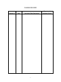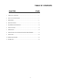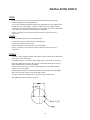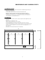
1
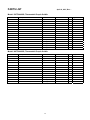
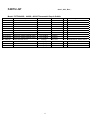
S6161-LR-FSE-010 0910-LP-527-3200 OPERATION AND SERVICE MANUAL FOR SHIPBOARD ELECTRIC DROP-IN GRIDDLE MODEL NUMBERS: 136TDI-VG, 148TDI-VG, 172TDI-VG, LANG MANUFACTURING DIVISION OF STAR MANUFACTURING INTERNATIONAL 10 SUNNEN DRIVE ST. LOUIS, MO, 63143 DISTRIBUTION STATEMENT THIS PUBLICATION IS REQUIRED FOR OFFICIAL USE OR FOR ADMINISTRATIVE OR OPERATIONAL PURPOSES. DISTRIBUTION IS LIMITED TO U.S. GOVERNMENT AGENCIES ONLY. OTHER REQUESTS FOR THIS DOCUMENT MUST BE REFERRED TO COMMANDER, NAVAL SEA SYSTEMS COMMAND, SEA 09, WASHINGTON, DC 20362 SUPERCEDURE NOTICE CANCELS AND SUPERCEDES S6161-LR-FSE-010 DATED MARCH 2002 AND ALL CHANGES THERETO Lang Manufacturing Part No. 2M-W357 Rev. - 10 Sunnen Drive, Phone: 314-678-6315, Fax: 314-781-2714 www.langworld.com 1 St. Louis, MO 63143 April, 24, 2007 MANUAL SUPPLEMENT FOR MARINE EQUIPMENT THIS EQUIPMENT IS APPROVED FOR INSTALLATION ONLY ON VESSELS GREATER THAN 65 FEET IN LENGTH IN ACCORDANCE WITH USCG REGULATIONS IN TITLE 46 CFR 110113. ANY WIRING USED IN THE INSTALLATION OF THIS APPLIANCE MUST BE STRANDED COPPER. 2 0910-LP-572-3200 APRIL 2007 IDENTIFYING TECHNICAL PUBLICATION SHEET 1. IDENTIFICATION DATA: 2. PURPOSE: THIS TECHNICAL PUBLICATION IS ISSUED FOR THE PURPOSE OF IDENTIFYING AN AUTHORIZED TECHNICAL MANUAL FOR NAVY USE AND FOR PROVIDING SUPPLEMENTAL TECHNICAL INFORMATION. A. MANUFACTURER: STAR MFG. INTERNATIONAL. B. CONTRACT NUMBER: _________________________________________ C. EQUIPMENT: GRIDDLE, SELF HEATING, ELECTRIC D. REQUISITION NUMBER: NOT REFERENCED E. NATIONAL STOCK NUMBER (NSN): ____________________________ F. TITLE: MAINTENANCE MANUAL FOR GRIDDLE, SELF HEATING, ELECTRIC G. DATE OF PUBLICATION: APRIL 2007 H. PREPARING ACTIVITY: DEFENSE GENERAL SUPPLY CENTER I. APPLICABLE TMCR NUMBER: 860172 J. EXTENT OF PROPOSED SUPPLEMENTAL DATA (10% MAXIMUM): 1% K. LIST OF TECHNICAL MANUAL FOR THIS EQUIPMENT PROCURED UNDER ANOTHER CONTACT: 3. ADDITIONAL COPIES: ADDITIONAL COPIES ARE AVAILABLE FROM: NAVAL PUBLICATION AND FORMS CENTER 5801 TABOR AVENUE PHILADELPHIA, PA 19120-5099 4. COVER: THE TECHNICAL MANUAL OUTSIDE COVER SHALL CONTAIN THE FOLLOWING STATEMENTS: PUBLISHED BY DIRECTION OF COMMANDER, NAVAL SEA SYSTEMS COMMAND 3 S6161-LR-FSE-010 0910-LP-527-3200 APPROVAL AND PROCUREMENT RECORD APPROVAL DATA FOR: GRIDDLE, SELF-HEATING, ELECTRIC TITLE OF MANUAL: MAINTENANCE MANUAL FOR: GRIDDLE, SELF-HEATING, ELECTRIC APPROVAL AUTHORITY: NAVAL SHIP SYSTEMS ENGINEERING STATION CONTRACT NUMBER NSN # OF UNITS APL/CID DLA441-92-M-2844 7310-01-359-2844 6 LG72MDI DLA441-92-M-Y175 7310-01-359-2845 13 LG36MDI DLA400-86-D-0090 7310-01-104-1214 14 LG48M REMARKS: DATE: MARCH 2002 CERTIFICATION: IT IS HEREBY CERTIFIED THAT THE TECHNICAL MANUAL PROVIDED UNDER CONTRACT NUMBER DLA441-92-M-2844, DLA441-92-M-Y175, DLA40086-D-0090 FOR LANG LG72MDI, LG36MDI, AND LG48M HAS BEEN APPROVED BY THE APPROVAL DATA SHOWN ABOVE: ______________________________ DIRECTOR, GOV’T CONTRACTS LANG MANUFACTURING COMPANY FSCM / CAGE #: 34931 4 CHANGE RECORD Change no. Date Title and/or Brief Description 5 Signature of Validating Officer TABLE OF CONTENTS CHAPTER PAGE 1. TABLE OF CONTENTS ............................................................................... 6 2. LIST OF ILLUSTRATIONS .......................................................................... 7 3. READ FIRST ................................................................................................. 8 4. SPECIFICATIONS ........................................................................................ 11 5. EQUIPMENT DESCRIPTION ...................................................................... 14 6. INSTALLATION ........................................................................................... 16 7. OPERATION.................................................................................................. 18 8. MAINTENANCE & TROUBLESHOOTING PROCEDURES .................... 19 9. PARTS LIST .................................................................................................. 24 10. WIRING DIAGRAMS ................................................................................... 26 11. WARRANTY ................................................................................................. 28 6 LIST OF ILLUSTRATIONS FIGURE # TITLE OF ILLUSTRATION PAGE # 1 Specification Sheets 11 to 20 2 MDI-36 Cut Out 21 3 MDI-48 Cut Out 22 4 MDI-72 Cut Out 23 5 Leg Pad Layout 27 6 Sensor Location (Calibration) 31 7 Wiring Diagram 208/240V 34 8 Wiring Diagram 480V 35 7 IMPORTANT CAUTION: CAUTION: CAUTION: DANGER: WARNING: NOTICE: NOTICE: NOTICE: CAUTION: CAUTION: READ FIRST THE GRIDDLE IS EXTREMELY HEAVY. FOR SAFE HANDLING, INSTALLER SHOULD OBTAIN HELP AS NEEDED, OR EMPLOY APPROPRIATE MATERIALS HANDLING EQUIPMENT (SUCH AS A FORKLIFT, DOLLY, OR PALLET JACK) TO REMOVE THE UNIT FROM THE SKID AND MOVE IT TO THE PLACE OF INSTALLATION. ANY STAND, COUNTER OR OTHER DEVICE ON WHICH GRIDDLE WILL BE LOCATED MUST BE DESIGNED TO SUPPORT THE WEIGHT OF THE GRIDDLE(S). SHIPPING STRAPS ARE UNDER TENSION AND CAN SNAP BACK WHEN CUT. THIS APPLIANCE MUST BE GROUNDED AT THE TERMINAL PROVIDED. FAILURE TO GROUND THE APPLIANCE COULD RESULT IN ELECTROCUTION AND DEATH. INSTALLATION OF THE UNIT MUST BE DONE BY PERSONNEL QUALIFIED TO WORK WITH ELECTRICITY. IMPROPER INSTALLATION CAN CAUSE INJURY TO PERSONNEL AND/OR DAMAGE TO EQUIPMENT. UNIT MUST BE INSTALLED IN ACCORDANCE WITH ALL APPLICABLE CODES. The data plate is located next to the grease drawer, behind access panel. The griddle voltage, wattage, serial number, wire size, and clearance specifications are on the data plate. This information should be carefully read and understood before proceeding with the installation. The installation of any components such as a vent hood, grease extractors, fire extinguisher systems, must conform to their applicable National, State and locally recognized installation standards. During the first few hours of operation you may notice a small amount of smoke coming off the griddle surface, and a faint odor from the smoke. This is normal for a new griddle and will disappear after the first few hours of use. ALWAYS KEEP THE AREA NEAR THE APPLIANCE FREE FROM COMBUSTIBLE MATERIALS. KEEP FLOOR IN FRONT OF EQUIPMENT CLEAN AND DRY. IF SPILLS OCCUR, CLEAN IMMEDIATELY, TO AVOID THE DANGER OF SLIPS OR FALLS. 8 IMPORTANT IMPORTANT WARNING: CAUTION: NOTICE: WARNING: CAUTION: READ FIRST KEEP WATER AND SOLUTIONS OUT OF CONTROLS. NEVER SPRAY OR HOSE CONTROL CONSOLE, ELECTRICAL CONNECTIONS, ETC. MOST CLEANERS ARE HARMFUL TO THE SKIN, EYES, MUCOUS MEMBRANES AND CLOTHING. PRECAUTIONS SHOULD BE TAKEN TO WEAR RUBBER GLOVES, GOGGLES OR FACE SHIELD AND PROTECTIVE CLOTHING. CAREFULLY READ THE WARNING AND FOLLOW THE DIRECTIONS ON THE LABEL OF THE CLEANER TO BE USED. Service on this, or any other, LANG appliance must be performed by qualified personnel only. Consult your LANG authorized service agent directory or call the factory at 314-678-6315 or www.langworld.com For the service agent nearest you. BOTH HIGH AND LOW VOLTAGES ARE PRESENT INSIDE THIS APPLIANCE WHEN THE UNIT IS PLUGGED/WIRED INTO A LIVE RECEPTACLE. BEFORE REPLACING ANY PARTS, DISCONNECT THE UNIT FROM THE ELECTRIC POWER SUPPLY. USE OF ANY REPLACEMENT PARTS OTHER THAN THOSE SUPPLIED BY LANG OR THEIR AUTHORIZED DISTRIBUTORS CAN CAUSE BODILY INJURY TO THE OPERATOR AND DAMAGE TO THE EQUIPMENT AND WILL VOID ALL WARRANTIES. 9 IMPORTANT LANG MANUFACTURING COMPANY MANUAL FOR MODEL ECO ELECTRIC CONVECTION OVENS ISSUE DATE FEBRUARY 1999 LANG MANUFACTURING COMPANY 10 SUNNEN DRIVE ST. LOUIS, MO 63143 ELECTRIC GRIDDLES PER: MIL-G-2338L MIL SPEC TYPE I, SIZE 2* LANG MODEL NUMBER LG-36M STAR MODEL NUMBER 136T-M TYPE I, SIZE 3* LG-72M 172T-M TYPE I, SIZE 5* LG-24M 124T-M TYPE I, SIZE 6* LG-48M 148T-M TYPE II- Use the same model number as above Then add for: STYLE 1- with Stand STYLE 2- with Castered Stand STYLE 3- with Bolt Down Stand TYPE III, SIZE 2* TYPE III, SIZE 3* TYPE III, SIZE 6* LGMDI36 LGMDI72 LGMDI48 136TDI-VG 172TDI-VG 148TDI-VG * N.S.A. for “Naval Shipboard Application”. All components will fit through a 26” X 66” watertight door. 10 MarineSeries Item No. Project Quantity Model: [136,148,172]TDIG Electric, Drop-In Model Griddles MARINE CONSTRUCTION FEATURES • • • • 3/4” thick precision machined, polished steel cooking surface Full parameter stainless steel top mounting flange Full front 3-1/2” wide x 1” deep stainless steel grease trough 8 quart capacity grease drawer, with marine latch & fully enclosed, easily removable sleeve [Two on 72” model] • Fully enclosed control compartment • Separate, insulated stainless steel griddle and control modules PERFORMANCE FEATURES • Thick griddle plate reduces hot & cold spots and retains heat • Highly polished, recessed surface and continuously welded mounting flange speeds cleanup • Heating elements incoloy sheathed, for long life • Elements are pressure clamped to bottom of griddle plate for more even heating • Recessed control panel protects control knobs • Accurate temperature control between 175 and 450˚F Model 136TDIG shown SIZING AND PERFORMANCE GUIDE Model/Width Surface Area Controls kW Input* ❏ 136TDIG 828 sq. in. 3 18-kW ❏ 148TDIG 1104 sq. in. 4 24-kW ❏ 172TDIG 1656 sq. in. 6 18/18-kW** CONTROLS • Independent temperature control every 12” • Heat on pilot lights for each control * 6-kW per foot of griddle ** Power input, two power connections required MARINE SHORT/BID SPECIFICATION Griddle shall be a LANG Manufacturing Marine Model 1__ [Specify width: 36”, 48” or 72”]TDIG, with: thermostat controls for each 12” of griddle width; 6-kW per foot of Incoloy sheathed heating elements, pressure clamped to plate bottom; 3/4” thick polished cooking surface; flanged flush-mount griddle surface module and recessed control panel module for easy installation in countertop. MARINE PRODUCT WARRANTY One year, parts & labor (Labor in U.S. only) Sheet No. LMSP-G1 (rev. 07/07) LANG MANUFACTURING - A DIVISION OF STAR MANUFACTURING INT’L, INC. • 10 SUNNEN DR. ST. LOUIS, MO 63143 TOLL FREE: 800.264-7827 • FAX: 314-781-3636 • www.langworld.com [136,148,172]TDIG Electric, Drop-In Model Griddles MARINE INSTALLATION REQUIREMENTS • • • E 440V or 480V, 3-phase power connection E E Two electric connections required for 72” unit Installation in approved cabinet or galley work center. [Provided by others] [3D & Front View 136TDIG] Model 136TDIG 148TDIG 172TDIG See below for rough openings re q u i red for griddle and control panel module Consult marine codes for installation requirements [3D & Front View 148TDIG] Top-Rough Opening Width Depth 36.8” 935mm 48.8” 1240mm 72.1” 1831mm • • 29.8” 756mm 29.8” 756mm 29.5” 748mm Controls-Opening Height Width 6.1” 156mm 6.1” 156mm 6.5”* 164mm [3D & Front View 172TDIG] Clearance from combustible surface 35.0” 889mm 47.0” 1194mm 25.2”* 641mm Sides: 2” Back : 2” Weight Actual Shipping 295 lbs. 120 kg 400 lbs. 167 kg 650 lb 295 kg 345 lbs. 186 kg 450 lbs. 239 kg 700 lb 318 kg Freight Class 85 85 85 * Two openings required in the Controls-Opening table for the 172TDIG model. Model 136TDIG 148TDIG 172TDIG Volts AC - Hz Total kW Amps - Three Phase Amps - Single Phase 208 - 50/60 240 - 50/60 440 - 50/60 480 - 50/60 208 - 50/60 240 - 50/60 440 - 50/60 480 - 50/60 208 - 50/60 240 - 50/60 440 - 50/60 480 - 50/60 18.0 18.0 18.0 18.0 24.0 24.0 24.0 24.0 36.0 [18/18]** 36.0 [18/18]** 36.0 [18/18]** 36.0 [18/18]** 50.0 43.3 23.6 21.7 75.0 65.0 36.8 32.5 50.0/50.0 43.3/43.3 23.6/23.6 21.7/21.7 86.5 75.0 N/A N/A 115.2 100.0 N/A N/A 86.5/86.5 75.0/75.0 N/A N/A ** Two connections. Due to continuous improvements, specifications subject to change without notice. Sheet No. LMSP-G1 (rev. 07/07) LANG MANUFACTURING - A DIVISION OF STAR MANUFACTURING INT’L, INC. • 10 SUNNEN DR. ST. LOUIS, MO 63143 TOLL FREE: 800.264-7827 • FAX: 314-781-3636 • www.langworld.com © 2004 Lang Manufacturing Company Printed in U.S.A. 10/04-M-12797 21 MDI-36 CUT OUT 22 MDI-48 CUT OUT 23 MDI-72 CUT OUT EQUIPMENT DESCRIPTION INTRODUCTION This manual contains the necessary information to install, operate, maintain, and service the Lang self-heating electric griddles. Replacement parts should be genuine Lang parts. Failure to use genuine Lang replacement parts may result in malfunction of the appliance or possible injury to the contractor or service technician. PURPOSE AND FUNCTION Electric griddles provide heated surface constantly regulated at a thermostatically set temperature. They are designed to cook a wide variety of food products including, but not limited to, eggs, hamburgers, fish, chicken and pancakes. CAPABILITIES These griddles are capable of cooking all types of products requiring contact wit a heated surface. ENVIRONMENTAL REQUIREMENTS The following minimum spacing from combustible surfaces must be maintained: Sides – 2 inches, Back – 2 inches ITEMS FURNISHED (Listed by Type and Style) Type I Griddle Size 2, 5, 6 1 ea. Griddle 4 ea. Legs 2 ea. Manuals, Technical Type I Griddle Size 3 1 ea. Griddle 8 ea. Legs 2 ea. Manuals, Technical Type II Griddle Style 1 1 ea. Griddle 1 ea. Stand 1 ea. Stand Hardware 2 ea. Manuals, Technical Type II Griddle Style 2 1 ea. Griddle 1 ea. Stand 1 ea. Stand Hardware 2 ea. Swivel Casters 2 ea. Rigid Casters 2 ea. Manuals, Technical 24 EQUIPMENT DESCRIPTION CONT’D Type II Griddle Style 3 1 ea. Griddle 1 ea. Bolt Down Stand 1 ea. Stand Hardware 2 ea. Manuals, Technical Type III Griddle Size 1 & 6 1 ea. Griddle 1 ea. Griddle Control Panel 2 ea. Manuals, Technical Type III Griddle Size 3 1 ea. Griddle 2 ea. Griddle Control Panel 2 ea. Manuals, Technical ITEMS REQUIRED An adequate supply of wire suitable for the loads and application specified on the data sheet must be provided. The data sheet is on Page 4 of this manual. TOOLS AND TEST EQUIPMENT REQUIRED For Installation: 1 set – Open End Wrenches 1 ea. – Flat Blade Screwdriver 1 ea. – Phillips Screwdriver 1 ea. – Wire Cutter/Stripper 1 ea. – AMP Probe 1 ea. – Voltmeter For Service: All of the above plus – 1 ea. – Needle Nose Pliers 1 ea. – Crimping Pliers 1 ea. – Allen Wrench Set 1 ea. – Temperature Meter 1 ea. – Very Small Flat Blade Screwdriver CONTROLS A mechanical snap action thermostat (100F-450F) controls each 12” section of the griddle. A red indicator lamp indicates that the griddle is heating. 25 INSTALLATION CAUTION: CAUTION: CAUTION: DANGER: WARNING: NOTICE: NOTICE: THE GRIDDLE IS EXTREMELY HEAVY. FOR SAFE HANDLING, INSTALLER SHOULD OBTAIN HELP AS NEEDED, OR EMPLOY APPROPRIATE MATERIALS HANDLING EQUIPMENT (SUCH AS A FORKLIFT, DOLLY, OR PALLET JACK) TO REMOVE THE UNIT FROM THE SKID AND MOVE IT TO THE PLACE OF INSTALLATION. ANY STAND, COUNTER OR OTHER DEVICE ON WHICH GRIDDLE WILL BE LOCATED MUST BE DESIGNED TO SUPPORT THE WEIGHT OF THE OVEN(S). SHIPPING STRAPS ARE UNDER TENSION AND CAN SNAP BACK WHEN CUT. THIS APPLIANCE MUST BE GROUNDED AT THE TERMINAL PROVIDED. FAILURE TO GROUND THE APPLIANCE COULD RESULT IN ELECTROCUTION AND DEATH. INSTALLATION OF THE UNIT MUST BE DONE BY PERSONNEL QUALIFIED TO WORK WITH ELECTRICITY. IMPROPER INSTALLATION CAN CAUSE INJURY TO PERSONNEL AND/OR DAMAGE TO EQUIPMENT. UNIT MUST BE INSTALLED IN ACCORDANCE WITH ALL APPLICABLE CODES. The data plate is located next to the grease drawer, behind access panel. The griddle voltage, wattage, serial number, wire size, and clearance specifications are on the data plate. This information should be carefully read and understood before proceeding with the installation. The installation of any components such as a vent hood, grease extractors, fire extinguisher systems, must conform to their applicable National, State and locally recognized installation standards. INSPECTION AND INSTALLATION INSPECTION AND INSTALLATION Upon receipt, check for freight damage, both visible and concealed. Visible damage should be noted on the freight bill at the time of delivery and signed by the carrier's agent. Concealed loss or damage means loss or damage which does not become apparent until the merchandise has been unpacked. If concealed loss or damage is discovered upon unpacking, make a written request for inspection by the carrier's agent within 15 days of delivery. All packing material should be kept for inspection. Do not return damaged merchandise to Lang Manufacturing Company. File your claim with the carrier. LOCATION Move the crate(s) containing the oven(s) as close to the place of installation as possible before removing the protective crating. Uncrate the oven(s) and move them as close as practical to the final installation site. 26 INSTALLATION CONT’D TYPE I Screw legs into the 3/8-16 weld nuts provided on the underside of the griddle. Place the griddle into its intended location. A 1 1/4-inch conduit knockout through the back and the bottom of the griddle body is located at the rear of the griddle. A 3-pole terminal block is provided for service connections and can be accessed through a removable panel on the back of the griddle. Use a supply wire suitable for at least 90 degree centigrade. Sizes 2, 5, and 6 have one electrical connection and size 3 has two electrical connections. TYPE II Construct stand and place into its intended location. For bolt down legs see illustration below for dimensions. Carefully place griddle onto its stand. Electric connection can be made at the rear of the griddle. Sizes 2, 5, and 6 have one electrical connection and size 3 has two electrical connections. TYPE III Carefully cut the countertop and the control panel cutouts to the clearance dimensions shown on the cutout illustrations. The griddle will have a control box and a griddle portion. Disconnect as necessary. Block the griddle over the hole in the top of the counter and put the gasket in place under the flange that will support the griddle. Position the control boxes close to there installed position. Attach the thermostat capillary tubes to the griddle. Drop the griddle into place and twist the hold-downs around the edge of the griddle that is now below the counter to lock the griddle in place. A separate box with a terminal block is provided for power connections. The griddle may now be connected to power 27 OPERATION NOTICE: CAUTION: CAUTION: During the first few hours of operation you may notice a small amount of smoke coming off the griddle surface, and a faint odor from the smoke. This is normal for a new griddle and will disappear after the first few hours of use. ALWAYS KEEP THE AREA NEAR THE APPLIANCE FREE FROM COMBUSTIBLE MATERIALS. KEEP FLOOR IN FRONT OF EQUIPMENT CLEAN AND DRY. IF SPILLS OCCUR, CLEAN IMMEDIATELY, TO AVOID THE DANGER OF SLIPS OR FALLS. OPERATING INSTRUCTIONS An understanding of how the griddle sections are controlled will be a valuable aid in loading your griddle. Each 12-inch section of your griddle is independently controlled by a temperature controller. The temperature control sensor is mounted in the center of each cooking section under the griddle plate. If the product is loaded directly over the temperature sensor, that section will turn on and the burner will heat the entire cooking section. If the product is loaded to the side, front or back of the temperature sensor, the thermostat will react to the temperature change much slower. During slow periods with minimal loads, do not load directly over the thermostat sensors as this will unnecessarily turn the burners on and overheat the remainder of the section not being utilized. Turn the product and continue cooking until it has reached its desired degree of doneness. Remove the product from the griddle. When reloading the griddle, first use the griddle surface on which a previous load was not placed. This will help insure the proper griddle temperature. INITIAL START-UP Prior to putting any griddle into full time operation at normal cooking temperatures, it must be thoroughly "seasoned" and dried out. Moisture absorption in the closed spaces, in the insulation and even inside the heating elements can cause future trouble if not properly treated. Before seasoning the griddle it is first necessary to remove the shipping preservative from the griddle surface. To do this, add a mild detergent to hot water and wash the griddle plate. Rinse with a damp sponge and dry with a clean rag. To "season" the griddle, set the thermostat dial to 300. Allow unit to come up to temperature and cycle off. Apply a thin coat of high-grade, non-salted vegetable oil to the griddle surface. Rub the oil into the griddle surface with the flat side of a spatula or a towel. Re-coat any dry spots that appear then wait 30 minutes and wipe off any excess oil. Repeat these steps at 350, 400, and 450. To “dry out” the Griddle, set the thermostat to 250 and turn on the power switch. Allow the unit to cycle at least 15 minutes at this heat level. Reset the thermostat to 350 allowing the same time. Reset the thermostat to 450 and allow the unit to maintain the temperature for a minimum of 4 hours. More time may be required if the unit will be operating in a moist or humid environment. If the unit is out of use for three or more days, a one-hour preheat schedule should be used, especially when exposed to high humidity and/or cool temperatures. 28 OPERATION CONT’D NORMAL OPERATION Each 12-inch section of your griddle is independently controlled by a temperature controller. The temperature control sensor is mounted in the center of each cooking section under the griddle plate. Turn the griddle thermostat to the desired temperature and allow 30 minutes to preheat. Once griddle has been preheated place product on the griddle and allow to cook. 29 MAINTENANCE AND CLEANING WARNING: CAUTION: NOTICE: WARNING: CAUTION: KEEP WATER AND SOLUTIONS OUT OF CONTROLS. NEVER SPRAY OR HOSE CONTROL CONSOLE, ELECTRICAL CONNECTIONS, ETC. MOST CLEANERS ARE HARMFUL TO THE SKIN, EYES, MUCOUS MEMBRANES AND CLOTHING. PRECAUTIONS SHOULD BE TAKEN TO WEAR RUBBER GLOVES, GOGGLES OR FACE SHIELD AND PROTECTIVE CLOTHING. CAREFULLY READ THE WARNING AND FOLLOW THE DIRECTIONS ON THE LABEL OF THE CLEANER TO BE USED. Service on this, or any other, LANG appliance must be performed by qualified personnel only. Consult your LANG authorized service agent directory or call the factory at 314-678-6315, or www.langworld.com For the service agent nearest you. BOTH HIGH AND LOW VOLTAGES ARE PRESENT INSIDE THIS APPLIANCE WHEN THE UNIT IS PLUGGED/WIRED INTO A LIVE RECEPTACLE. BEFORE REPLACING ANY PARTS, DISCONNECT THE UNIT FROM THE ELECTRIC POWER SUPPLY. USE OF ANY REPLACEMENT PARTS OTHER THAN THOSE SUPPLIED BY LANG OR THEIR AUTHORIZED DISTRIBUTORS CAN CAUSE BODILY INJURY TO THE OPERATOR AND DAMAGE TO THE EQUIPMENT AND WILL VOID ALL WARRANTIES. DAILY CLEANING Empty the grease drawer or whenever it is 3/4 full by pulling strait out toward the front. It is easily removed for washing. Clean the exterior of the appliance with Lang Mfg. Prima Shine (72804-41) cleaner to maintain a gleaming appearance. Keep the griddle surface clean. After each cooking load, scrape the griddle surface to remove any carbonized grease WEEKLY CLEANING Once a week (or when necessary) the griddle surface should be cleaned and reseasoned. Use Lang Mfg Carbon Release (72804-32). Rub with the grain of the metal, being careful not to scrape the splashguard. Be sure to rinse thoroughly and re-season to prevent rusting and corrosion. 30 MAINTENANCE AND CLEANING CONT’D CALIBRATION CHECK Set the griddle temperature to 350F on all sections (it should take approximately 22 minutes to reach temperature). Let the griddle reach 350F and cycle off and on at least three times. Measure 6” from the left, and 11 1/2” from the front of the plate for the first checkpoint. This will check the center of the sensor for the first cooking section. Each checkpoint is located every 12” to the right from the last point, and always 11 1/2” from the front. (See illustration below.) CALIBRATION A 1/16” flat blade screwdriver with a 2” shaft is required to make adjustments on the thermostat. Maintain the oven temperature at 350. Without turning the thermostat, remove the knob. Locate the adjustment screw at the base of the shaft and insert the screwdriver. Grasp the shaft and turn the screwdriver counter clockwise to increase temperature and clockwise to decrease temperature (1/8 of a turn will move the temperature 5-7 in either direction). Reinstall the oven knob and recheck the oven temperature. 48" 2" 6" 12" 12" 12" 6" 11 1/2" 30" 11 1/2" 5" 31 MAINTENANCE AND CLEANING CONT’D ELEMENT REMOVAL Disconnect power from griddle. Prop griddle plate up. Disconnect power wire attached to heating element terminals. Mark or identify each wire to ensure correct replacement on new heating element. Inspect for frayed ends, broken strands and grease soaked insulation. Replace as necessary. Remove the two sheet metal screws securing the thermostat capillary tube clip to the element pan. Pull the clip and the tube down and out of the center slot of the element pan. Take care not to break the capillary tube, as it may be brittle from prolonged exposure to high temperature. Remove the nuts and washers retaining the element pan and pressure plate. Drop the element pan straight down until studs are cleared and pull forward out of griddle body. The elements will normally drop down with the element pan and are now accessible for replacement as necessary. Compare voltage and wattage marking of old element with new one to ensure proper replacement. Reverse the removal procedure to install the new element. Be sure the nuts holding the element pan are snug as this will assure proper contact between the element and griddle plate. The capillary tube bulb must also be tightly clamped against the griddle plate to obtain proper temperature control. THERMOSTAT REPLACEMENT Disconnect power from griddle. Prop griddle plate up. Loosen the two sheet metal screws securing the thermostat capillary tube clip to the element pan. Gently pull the thermostat capillary tube from the clip. Remove the two sheet metal screws from the rear of the control panel box and pull off the box cover. Remove thermostat control knob. Loosen and remove the two screws securing the thermostat body to the front panel. Remove wires from thermostat terminals. Mark for proper replacement. Reverse this procedure for replacement. PILOT INDICATOR REPLACEMENT Disconnect power from griddle. Prop griddle plate up. Remove the two sheet metal screws from the rear of the control panel box and pull off the box cover. Remove the wires from the pilot indicator. The pilot light is held firmly in place by means of a spring metal speed nut on the back. Remove the pilot indicator by removing the speed nut and pulling it out through the front. It may be necessary to break the pilot light in two to remover he speed nut. Install the new pilot light and hold in place with speed nut. Reverse the procedure to reinstall. 32 TROUBLE SHOOTING SYMPTOM PROBLEM REMEDY Whole griddle will not heat Circuit breaker turned off Griddle not turned on Improper connection Improperly Phased Turn on Turn on Connect per wiring diagram Phase per wiring diagram One section will not heat. Defective elements Defective thermostat Replace elements Replace thermostat Griddle is burning product Griddle is out of calibration Calibrate Griddle is undercooking product Griddle is out of calibration Calibrate Indicator light will not come on Defective Indicator light Replace Indicator light TECHNICAL DATA Part# 2N-11030-29 2N-11030-30 2N-11030-31 2N-11030-04 Description I/S Element O/S Element Element Element Volts 208/240 208 480 380 Watts 4500/5991 1491 5991 5991 Amps 22/26 8 12.5 16 GRIDDLE LINE AMPERAGE, AND WATTAGE NOMINAL AMPS PER LINE Type: I, II, III 24” 36” 48” 72” #1 #2 TOTAL K.W. 12.0 18.0 24.0 18.0 18.0 L1 50.0 50.0 75.0 50.0 50.0 208 Volt L2 28.8 50.0 75.0 50.0 50.0 L3 28.8 50.0 50.0 50.0 50.0 THREE PHASE 240 Volt L1 L2 L3 43.3 25.0 25.0 43.3 43.3 43.3 65.0 65.0 43.3 43.3 43.3 43.3 43.3 43.3 43.3 33 L1 21.7 21.7 32.5 21.7 21.7 SINGLE PHASE 480 Volt L2 12.5 21.7 32.5 21.7 21.7 L3 12.5 21.7 21.7 21.7 21.7 208V 57.7 86.5 115.4 86.5 86.5 240V 50.0 75.0 100.0 75.0 75.0 34 208/240 WIRING DIAGRAM 35 480 WIRING DIAGRAM PARTS LIST April 18, 2007, Rev. – Model: 136TDI-440VG, Thermostatic Drop-In Griddle Part No. 2E-30500-02 2E-30500-03 2E-30500-05 2E-30500-07 2J-31601-02 2N-11030-31 2N-11030-48 Description TRM STRP 4 POLE 30A 600V TRM STRP 6 POLE 30A 300V TRM STRP 8 POLE 30A 300V TRM BLOCK 3PLELRGE 125AMP PILOT LT 480V 6LEAD BLK ELMNT GRID 480V 5991W ELE GRD 440V 5991W XL/LG Vendor Cooper-Bussman Cooper-Bussman Cooper-Bussman All-West Fasteners Solico Caloritech Inc. Caloritech Inc. Vendor # TB30004-00 TB30006 TB30008 162-04-3L 1854-1-20-20310 IXI-11030-31 IXI-11030-48 2P-50100-05 GROOVED GRIDDLE CLEANING Chef Aid MFG 50100-05 2P-50100-051 GROOVED GRIDDLE BRUSH REPL Chef Aid MFG 50100-051 2P-50100-052 GROOVED GRIDDLE BRUSH REPL Chef Aid MFG 50100-052 2T-30402-08 K9-50302-05 K9-MDI-105-3 K9-MDI-212-2 Y9-70701-16 STAT ADJ 450o 72 C/T ELEMENT PAN ASSY XL/LG GRIDDLE PLATE ASSY 3' GREASE BUCKET ASSY 2' KNOB ASSY 450o A, Black Invensys Star Mfg Int. Star Mfg Int. Star Mfg Int. Star Mfg. Int. SP-173-72 50302-05 MDI-105-3 MDI-212-2 70701-16 QTY Applications 1 3 3 3 136TDI-440VG 136TDI-440VG 136TDI-480VG 136TDI-440VG 3 136TDI-440VG 1 1 3 136TDI-440VG 136TDI-440VG 136TDI-440VG Model: 148TDI-440VG, Thermostatic Drop-In Griddle Part No. 2E-30500-02 2E-30500-03 2E-30500-05 Description TRM STRP 4 POLE 30A 600V TRM STRP 6 POLE 30A 300V TRM STRP 8 POLE 30A 300V Vendor Cooper-Bussman Cooper-Bussman Cooper-Bussman Vendor # TB30004-00 TB30006 TB30008 QTY Applications 2E-30500-07 TRM BLOCK 3PLELRGE 125AMP All-West Fasteners 162-04-3L 1 148TDI-440VG 2J-31601-02 2N-11030-31 2N-11030-48 PILOT LT 480V 6LEAD BLK ELMNT GRID 480V 5991W ELE GRD 440V 5991W XL/LG Solico Caloritech Inc. Caloritech Inc. 1854-1-20-20310 IXI-11030-31 IXI-11030-48 4 4 4 148TDI-440VG 148TDI-480VG 148TDI-440VG 2P-50100-05 GROOVED GRIDDLE CLEANING Chef Aid MFG 50100-05 2P-50100-051 GROOVED GRIDDLE BRUSH REPL Chef Aid MFG 50100-051 2P-50100-052 GROOVED GRIDDLE BRUSH REPL Chef Aid MFG 50100-052 2T-30402-08 K9-MDI-105-4 Y9-70701-16 STAT ADJ 450o 72 C/T GRIDDLE PLATE ASSY 4' KNOB ASSY 450o A, Black Invensys Star Mfg Int. Star Mfg. Int. SP-173-72 MDI-105-4 70701-16 4 1 4 148TDI-440VG 148TDI-440VG 148TDI-440VG 36 PARTS LIST June 1, 2011, Rev. – Model: 172TDI-240VG, -440VG, -480VG Thermostatic Drop-In Griddle Part No. 2E-30500-07 2J-31601-02 2J-31601-01 2N-11030-31 2N-11030-48 2N-11030-12 2P-50100-05 2P-50100-051 2P-50100-052 2T-30402-08 K9-MDI-105-6 K9-MDI-212-6 Description TRM BLOCK 3PLELRGE 125AMP PILOT LT 480V 6LEAD BLK PILOT LT 250V 6LEAD BLK ELMNT GRID 480V 5991W ELE GRD 440V 5991W XL/LG ELE GRD SPECL 240V5991W GROOVED GRIDDLE CLEANING GROOVED GRIDDLE BRUSH REPL GROOVED GRIDDLE BRUSH REPL STAT ADJ 450o 72 C/T GRIDDLE PLATE ASSY 6' GREASE BUCKET ASSY MDI-72 Y9-70701-16 KNOB ASSY 450°F A, Black Vendor All-West Fasteners Solico Solico CCI Thermal Tech CCI Thermal Tech CCI Thermal Tech Chef Aid MFG Chef Aid MFG Chef Aid MFG Invensys Lang Mfg Lang Mfg Lang Mfg. 37 Vendor # 162-04-3L 1854-1-20-20310 2152-1-23-20110 IXI-11030-31 IXI-11030-48 IXI-L11030-12 50100-05 50100-051 50100-052 SP-173-72 MDI-105-6 MDI-212-6 70701-16 QTY 2 6 6 6 6 6 Applications 172TDI-440VG, 480VG 172TDI-440VG, 480VG 172TDI-240VG 172TDI-480VG 172TDI-440VG, 480VG 172TDI-240VG 6 1 2 172TDI-240VG, 440VG, 480VG 172TDI-240VG, 440VG, 480VG 172TDI-240VG, 440VG, 480VG 6 172TDI-240VG, 440VG, 480VG WARRANTY Lang Manufacturing Limited Warranty to Commercial Purchasers* (Domestic U.S., Hawaii, & Canadian Sales only.) Lang Manufacturing Equipment (“Lang Equipment”) has been skillfully manufactured, carefully inspected and packaged to meet rigid standards of excellence. Lang warrants its Equipment to be free from defects in material and workmanship for (12) twelve consecutive months, with the following conditions and subject to the following limitations. IV. This warranty does not cover routine general maintenance, periodic adjustments, as specified in operating instructions or manuals, and consumable parts such as quartz elements, or labor costs incurred for removal of adjacent equipment or objects to gain access to Lang Equipment. This warranty does not cover defects caused by improper installation, abuse, careless operation, or improper maintenance of equipment. I. This parts and labor warranty is limited to Lang Equipment sold to the original commercial purchaser/users (but not original equipment manufacturers), at its original place of installation, in the continental United States, Hawaii and Canada. V. THIS WARRANTY IS EXCLUSIVE AND IS IN LIEU OF ALL OTHER WARRANTIES, EXPRESSED OR IMPLIED, INCLUDING ANY IMPLIED WARRANTY OF MERCHANTABILITY OR FITNESS FOR A PARTICULAR PURPOSE, EACH OF WHICH IS HEREBY EXPRESSLY DISCLAIMED. THE REMEDIES DESCRIBED ABOVE ARE EXCLUSIVE AND IN NO EVENT SHALL LANG BE LIABLE FOR SPECIAL, CONSEQUENTIAL OR INCIDENTAL DAMAGES FOR THE BREACH OR DELAY IN PERFORMANCE OF THIS WARRANTY. Quartz elements are warranted for ninety(90) days from the date of installation. II. Damage during shipment is to be reported to the carrier, is not covered under this warranty, and is the sole responsibility of purchaser/user. III. Lang, or an authorized service representative, will repair or replace, at Lang’s sole election, and Lang Equipment, including but not limited to, safety valves, gas and electric components, found to be defective during the warranty period. As to warranty service in the territory described above, Lang will absorb labor and portal to portal transportation costs (time & mileage) for the first (12) twelve months from the date of installation or eighteen (18) months from date of shipment from Lang Manufacturing, which ever comes first. VI. Lang Equipment is for commercial use only. If sold as a component of another(OEM) manufacturer’s equipment, or if used as a consumer product, such Equipment is sold AS IS and without any warranty. 38