1
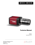
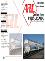
SALES OFFICES
Headquarters
St. Charles, MO 63301
(636) 940-5000
Northeastern District
475 Market Street
Elmwood Park, NJ 07407
(201) 794-6828
Southern District
1610 Woodstead Court
Suite 230
The Woodlands, TX 77380-3403
(281) 364-0190
Mid-Western District
15 Spinning Wheel Road
Suite 108
Hinsdale, IL 60521-2983
(630) 325-4600
Canadian District
ARL Canada Limited
1 Avenue Holiday, East Tower
Suite 501
Pointe-Claire, Quebec H9R 5N3
(514) 697-5958
ARL makes no representations or warranties, expressed or implied, with respect to the contents hereof, and assumes no contractual or other
liability with respect to any use which customer may make of this Service Manual. For further information, telephone or write either the nearest
representative of American Railcar Leasing LLC, or phone directly to American Railcar Leasing LLC, St. Charles, Missouri at 636-940-5000.
© 2012 American Railcar Leasing LLC
Printed
in
U.S.A.
CENTER FLOW ® PRESSUREAIDE ® CAR
CENTER FLOW ® PRESSUREAIDE ® CAR
TABLE OF CONTENTS
GENERAL MAINTENANCE
Part I. PAGE
Introduction . . . . . . . . . . . . . . . . . . . . . . . . . . . . . . . . . . . . . . . . . . . . . . . . 2
Part II. Pre-Trip Car Inspection . . . . . . . . . . . . . . . . . . . . . . . . . . . . . . . . . . . . . . . 4
RUPTURE DISC ASSEMBLY
PRESSURE RELIEF VALVES
Part III. Air Requirements . . . . . . . . . . . . . . . . . . . . . . . . . . . . . . . . . . . . . . . . . . . . 5
The rupture disc assembly must be inspected
annually, or if the security seal is broken.
The pressure relief valves must be visually
inspected as part of the preload inspection to
remove any dirt or debris that may have collected
in the discharge opening. The discharge pressure
must be tested annually. The pressure test can be
performed either on the car, or on a test bench.
Part IV. Operating Instructions . . . . . . . . . . . . . . . . . . . . . . . . . . . . . . . . . . . . . . . . . .
Operating Controls . . . . . . . . . . . . . . . . . . . . . . . . . . . . . . . . . . . . . .
General Unloading Instructions . . . . . . . . . . . . . . . . . . . . . . . . . . . . . .
Hook-up . . . . . . . . . . . . . . . . . . . . . . . . . . . . . . . . . . . . . . . . . . . . . .
Pressurization . . . . . . . . . . . . . . . . . . . . . . . . . . . . . . . . . . . . . . . . . . .
Unloading . . . . . . . . . . . . . . . . . . . . . . . . . . . . . . . . . . . . . . . . . . . . .
Unloading Assists (Vibration and Fluidization) . . . . . . . . . . . . . . . . . . .
6
6
7
8
8
9
9
Part V. General Maintenance . . . . . . . . . . . . . . . . . . . . . . . . . . . . . . . . . . . . . . . .
Pressure Gauges . . . . . . . . . . . . . . . . . . . . . . . . . . . . . . . . . . . . . . . . .
Rupture Disc . . . . . . . . . . . . . . . . . . . . . . . . . . . . . . . . . . . . . . . . . . .
Pressure Relief Valves . . . . . . . . . . . . . . . . . . . . . . . . . . . . . . . . . . . . .
Hatches . . . . . . . . . . . . . . . . . . . . . . . . . . . . . . . . . . . . . . . . . . . . . . .
10
10
11
12
13
1. Break the security wire and remove the four
nuts securing the weather cover.
2. Visually inspect the disc looking for signs of
rupture, tears or holes. An air leak test can be
performed by pressurizing the car body to 10 psig
and using a soap solution.
PRESSURE SETTINGS
Car body valve - 14.5 psig +/- 0.5 psig.
Air manifold valve - 16.0 psig +/- 0.5 psig.
3. If the disc requires replacement, depressurize
the car and ensure the pressure gauges read “zero.” 1. Pressure relief valve maintenance cannot be
performed in the field. If the “start to discharge”
4. Remove the four bolts, separate the flanges
pressure falls outside the +/- 0.5 psig tolerance,
and discard the old rupture disc.
the valve can be replaced in kind or returned to
American Railcar Leasing for rebuilding. This
5. Inspect and clean the disc seating surfaces on
includes adjustment of the start to discharge
each flange removing any nick or burrs then
pressure. Oil and grease must be kept away from the
lightly polish with emery cloth.
inside of the valve as it is designed to operate without
lubrication.
6. Remove the new rupture disc from the
packaging and visually examine to ensure it is in
2. To remove the pressure relief valves, use a
good condition. Confirm the pressure rating is
standard open-end wrench to engage the flats on
20 psig. The disc must be specifically manufacthe bottom of the valve. Do not apply force to
tured for use in the rupture disc holder assembly. the valve body or the discharge connection.
7. Place the rupture disc on the inlet flange. The
convex side of the disc must be in the up position so pressure inside the car will be against the
concave side of the disc.
8. Replace the upper flange. Install the four
bolts finger tight to ensure all components are
properly aligned and seated. Torque the nuts to
34-38 ft-lbs. Do not over tighten as damage to the
rupture disc may occur.
Part VI. Cleaning . . . . . . . . . . . . . . . . . . . . . . . . . . . . . . . . . . . . . . . . . . . . . . . . . . . 15
Part VII. Troubleshooting . . . . . . . . . . . . . . . . . . . . . . . . . . . . . . . . . . . . . . . . . . . . . 16
Part VIII. Parts List . . . . . . . . . . . . . . . . . . . . . . . . . . . . . . . . . . . . . . . . . . . . . . . . . . . 19
Part IX. Specification Sheet . . . . . . . . . . . . . . . . . . . . . . . . . . . . . . . . . . . . . . . . . . 24
Part X. ARL CF 5650 Pressureaide
Introduction . . . . . . . . . . . . . . . . . . . . . . . . . . . . . . . . . . . . . . . . . . . .
Specification Sheet . . . . . . . . . . . . . . . . . . . . . . . . . . . . . . . . . . . . . . .
Operation Equipment and Locations . . . . . . . . . . . . . . . . . . . . . . . . . .
Operation Instruction and Controls . . . . . . . . . . . . . . . . . . . . . . . . . .
Standard Hatch Arrangement . . . . . . . . . . . . . . . . . . . . . . . . . . . . . . . .
Hatch Lever Adjustment Instructions . . . . . . . . . . . . . . . . . . . . . . . . . .
Unloading Operations . . . . . . . . . . . . . . . . . . . . . . . . . . . . . . . . . . . . .
Cleaning . . . . . . . . . . . . . . . . . . . . . . . . . . . . . . . . . . . . . . . . . . . . . . .
General Maintenance . . . . . . . . . . . . . . . . . . . . . . . . . . . . . . . . . . . . .
Troubleshooting . . . . . . . . . . . . . . . . . . . . . . . . . . . . . . . . . . . . . . . . .
3. Reinstall the valve by applying a moderate
coating of pipe compound or plumber’s tape to
the male threads of the pipe connection. Keep
the compound away from the first few threads to
prevent contamination of the valve, car or piping.
DUST CAPS
Inspect the chains, gaskets and cam lever hardware
on each dust cap. Replace damaged or missing
parts.
25
26
27
29
32
33
34
36
39
16
9. Reinstall the cover, tighten nuts 20-25 ft-lbs.
and install a new security wire with lead seal.
40
1
PART I.
CENTER FLOW ® PRESSUREAIDE ® CAR
CENTER FLOW ® PRESSUREAIDE ® CAR
INTRODUCTION
GENERAL MAINTENANCE
The car must be depressurized before performing any maintenance function. Open the blow down
valve, then one fluidizing, one by-pass valve and one product valve. Confirm the pressure gauges read
“zero”.
HATCH GASKET REPLACEMENT
PRESSURE GAUGES
Remove the old gasket by inserting a flat head
screwdriver along the outer wall of the gasket
groove and prying underneath the gasket. Take
care not to gouge the metal surface. Once
enough of the gasket is exposed, pull the
remainder out by hand.
The pressure gauges must be calibrated on an
annual basis. Two tee connections are located
on the back side of the pressure gauge housing.
These fittings connect the gauge inlet lines, the
pressure gauges and the petcocks.
Do not pry against the inner wall of the
gasket groove, as this could result in damage to
the dovetail.
1. Clean the gasket groove with a commercial
adhesive remover to remove any residue then
wipe down both sides of the new gasket and
allow to dry.
Figure 1. Center Flow® Pressureaide® Car
1. Remove the petcocks and connect calibrated
test gauges to the tees. If necessary, the gauge
inlet lines can be cleared with compressed air.
2. Close all product and air valves except for one
fluidizing valve.
3. Connect an air supply line and pressurize the
car to 10.0 psig.
The ARL Pressureaide® pressure differential Center Flow® covered hopper car is designed to handle
dry bulk commodities. With operating pressures up to 14.5 psig, fast, efficient unloading for long
distances can be achieved. Unloading rates up to 100,000 lbs/hour may be obtained depending
upon the commodity and unloading system.
2. Apply a thin layer of Scotch-Grip EC1357
Contact Adhesive to the bottom of the gasket.
Allow the adhesive to set until the surfaces
become tacky.
4. The pressure reading between the car gauge
and the test gauge must be within 1.0 psig. If
the car gauge falls outside this range, remove the
gauge and replace.
The Pressureaide® car has many of the famous Center Flow® car design features: centerline loading,
unloading, complete sanitation and ease of operation. Designed to operate with standard positive
displacement blowers, this car may be used with equipment compatible with pressure sleds. As safety
is a prime consideration for American Railcar Leasing LLC, the Pressureaide® car is equipped with
two pressure relief valves, a rupture disc and a vacuum relief valve.
3. Install the gasket by slipping one edge into the
dovetail. Repeat this every 90 degrees. Continue
pressing the gasket into the dovetail with thumb
pressure or the heel of your hand. A small roller
can also be used. Make sure the gasket is properly
seated.
5. If there is no pressure reading, stop the blower
and open the blow down valve to allow the car to
depressurize.
The Pressureaide® car is unmatched by any railcar in its class when it comes to sanitation,
maintenance and unloading performance.
4. Wipe away any excess adhesive.
5. Close the cover, center on the hatch ring and
latch all cam levers. Check lever closing force.
2
6. Disconnect the fitting at the back of the gauge
panel, close the petcock and using compressed air,
blow back through the gauge line to clear away
any product that may be causing a blockage.
7. Reassemble the gauges and retest.
39
CENTER FLOW ® PRESSUREAIDE ® CAR
CENTER FLOW ® PRESSUREAIDE ® CAR
CLEANING
8'-3 1/2"
DRYING PROCESS
1. After all compartments have been cleaned, be
sure all the fluidizing valves are in the full open
position to allow airflow through the membranes
until the compartment is dry.
2. Shut down the blower and allow dry residual
air to vent from the car to avoid any potential for
pressure to build in the car or manifold.
3. Close and secure all hatches.
4. Close the product valves and re-install the caps
or closure plates on the clean out ports.
5. Restart the blower and pressurize the car to 10
psig.
6'-4"
5'-4 1/4"
5'-0"
5'-0"
5'-0"
5'-4 1/4"
6'-4"
8'-3 1/2"
7. After drying the last compartment, open the
by-pass air and product valves and allow airflow
for two minutes.
8. Shut down the blower. The car will
depressurize through the product valves. Ensure
the pressure gauges read “zero” before going to
step 9. Open blow down valve to ensure there is
no pressure in the car body.
Figure 2. Standard 8-Hatch Arrangement For Models 5000 and 5001
Figure 2 shows the standard roof hatch and bulkhead arrangement for the models 5000 and 5001
Pressureaide® cars. Each compartment has two hatches located on the car’s longitudinal centerline.
Intermediate bulkheads are designed to permit simultaneous loading of adjacent compartments from
one hatch.
9. Remove the discharge hoses and dust caps or
closure plates from the clean out ports.
10. Inspect the clean out ports. Swab out any
remaining water and residue. Re-install the quick
disconnect caps or closure plates.
11. Disconnect the air supply line.
6'-5 1/2"
9'-1"
5'-4 1/4"
6'-3"
6'-2 3/16"
6'-3"
5'-4 1/4"
9'-1"
6'-5 1/2"
12. Close all valves. Install and secure the quick
6. Open the product valve on an end compartdisconnect caps on the air inlets and product
ment and allow airflow for two minutes to clear
any remaining water from the product line. Close discharge connections.
the valve and repeat the procedure on the next
hopper.
Figure 3. Standard 8-Hatch Arrangement For Models 5003 and 5007
Figure 3 shows the standard roof hatch and bulkhead arrangement for the models 5003 and 5007
Pressureaide® cars. Each compartment has two hatches located on the car’s longitudinal centerline.
Intermediate bulkheads are designed to permit simultaneous loading of adjacent compartments from
one hatch.
38
3
PART II.
CENTER FLOW ® PRESSUREAIDE ® CAR
CENTER FLOW ® PRESSUREAIDE ® CAR
PRE-TRIP CAR INSPECTION
CLEANING
The Pressureaide® car is a special piece of equipment, as such, it requires regular preventative
maintenance. Part of this program includes a thorough pre-trip inspection prior to loading.
PRESSURE RELIEF VALVE, RUPTURE DISC,
VACUUM RELIEF VALVE LOCATED ON ROOF
“A”
END
FLUIDIZING AIR VAVLES
BLOWDOWN
VALVE
FLUIDIZING AIR VALVES
"A"
Comp.
PRESSURE
GAGES
“B”
END
"AC"
Comp.
PRODUCT
VALVE
AIR INLET
(FAR SIDE)
BY-PASS AIR
VALVE
PRODUCT
DISCHARGE
CLEAN-OUT PORT
MANIFOLD PRESSURE
RELIEF VALVE
"BC"
Comp.
"B"
Comp.
AIR INLET
(NEAR SIDE)
BY-PASS AIR
VALVE
BEFORE LOADING
1. If the car is to be cleaned, follow the
procedures on page 15.
2. Ensure there is no water in the air manifold
and that the product manifold and membranes
are clean and dry.
3. Inspect all hatch covers, locking mechanisms
and safety catches for proper operation. Ensure
gaskets are clean and in good condition.
4. Inspect and operate all control valves
(product, by-pass air, fluidizing air and
blowdown) to ensure they are in proper working
condition.
5. Inspect all dust caps. Ensure gaskets are in
place and in good condition. Attachment chains
and cam levers must be intact.
6. Inspect pressure gauges and protective covers.
Be sure the gauges read zero with car
depressurized and the cover is not broken.
CLEANING PROCESS
1. In-plant confined space entry procedures must
be followed to enter the car.
1. Start the blower to establish airflow through
the membranes. It is critical to maintain airflow
during the cleaning process.
2. Before opening hatches or removing caps,
open the blow down valve, air inlet valve, by-pass
valve and product valves to depressurize the car
body and manifold system.
SIDE SILL
CLEAN-OUT PORT
2. Wet washing can be accomplished using a
hand held hose or a roto-jet inserted into an
open hatch. Move from hopper to hopper, as
necessary, to clean entire railcar.
3. Open all hatches on top of the car.
Figure 4. Operating Equipment
PRE-TRIP CHECKLIST
WASHING PROCEDURES - PREPARATION
4. Connect a positive displacement blower to the
air inlet connections.
8. If the cleanout port has a flanged cover,
ensure its gasket is properly installed and all
fasteners properly tightened. If the cleanout port
has a dust cap arrangement, ensure the cap is
properly installed, its gasket is in good condition
and a proper locking seal is applied to the
operating levers.
3. After cleaning, continue the airflow through
the membranes until dry.
5. Attach product discharge hoses to each side of
the car to direct the flow of air, water and residual
product away from the personnel and the work
area.
6. Close the two by-pass valves and open all of
the fluidizing valves to the full open position.
9. Ensure all valves are closed prior to loading
product into the car. If venting is required, it
may be provided for by opening the blowdown
valve or a hatch. Proper filters may be required
to minimize dusting.
7. Open all of the product valves.
8. Remove the bolted cover plates from the clean
out port on each compartment.
AFTER LOADING
1. Check all caps for secure installation.
2. Ensure blowdown valve is closed.
3. Ensure cover over pressure gauges is closed.
4. All hatches must be closed and all holddowns
properly engaged in the closed position.
7. Inspect all rubber hoses to ensure the hose
clamps are properly installed and tightened and
that the hoses are intact.
4
37
CENTER FLOW ® PRESSUREAIDE ® CAR
PART III.
CENTER FLOW ® PRESSUREAIDE ® CAR
AIR REQUIREMENTS
CLEANING
GENERAL INSTRUCTIONS & CAUTIONS
1. In-plant confined space entry procedures must
be followed to enter the car.
2. Ensure the car is not under pressure before
opening hatches or removing caps. Open the
blow down valve, air inlet valve, by-pass valve and
product valves to depressurize the car body and
manifold system, then check the pressure gauges
to confirm all readings are zero.
3. If using ladders, they must be equipped with
rubber feet to protect the interior lining.
4. Never place a ladder on the aeration
membrane as damage will result.
The Pressureaide® car has been designed to
operate with air supplies from 200 CFM to
1000 CFM (CFM=Cubic Feet Per Minute).
The air requirement for a particular system
depends on the diameter and configuration of
the conveying line and the characteristics of the
material being conveyed. To determine the
air requirements for a specific unloading
system, furnish your ARL representative
with the details of the system. As a general
guide for air requirements in low-pressure
pneumatic systems, refer to the following chart:
6. Do not direct high-pressure water at the
membranes.
7. Steam cleaning or grit based blast should never
be employed on cars with interior lining.
8. The most common methods for cleaning the
interior of an ARL Pressureaide® car is using
either of two proven methods: wet washing or
dry scraping. If dry scraping, use pliable plastic
tools and use extreme care not to damage the
lining or membranes.
AIR PRODUCT LINE VOLUME
SIZE
4-inch (pipe) . . . . . . . . 440 CFM
5-inch (pipe) . . . . . . . . 680 CFM
6-inch (pipe) . . . . . . . 1000 CFM
9. Entry into the car is gained through the
manway openings. Do not remove the plenum
plates from the bottom of the car.
CAUTION:
UNDER NO CIRCUMSTANCES SHOULD
MORE THAN 1000 CFM BE USED TO
PRESSURIZE THE CAR NOR SHOULD
CAR PRESSURE EXCEED 14.5 PSIG.
5. Avoid direct impingement of high-pressure
water on the safety relief valve, vacuum relief
valve and the rupture disc inlets located in the
roof of the “A” and “B” hoppers.
Best results are obtained by using a positive
displacement blower which will develop air flow
(CFM) at a minimum of 14.5 psig. However,
there are many other types of blowers and air
compressors that produce adequate air flow to
operate the Pressureaide® car.
Large industrial plant systems, which produce an
adequate air flow, may be used to operate the
Pressureaide® car provided they are equipped
with a pressure regulator that limits the pressure
to 20 psig, an adequate water trap and a good
filter.
NOTE:
WHEN USING ANY AIR SOURCE, THE AIR
MUST BE CLEAN, FREE FROM OIL AND
WATER AND ITS TEMPERATURE MUST
NOT EXCEED 250ºF. FAILURE TO DO SO
MAY RESULT IN DAMAGE TO THE
CAR’S MEMBRANES.
36
The Pressureaide® car has two membranes in
the bottom of each compartment. Air directed
through the membranes fluidizes the lading and
pressurizes the car. The fluidization breaks
down the internal strength of the lading and the
pressurization provides the energy to convey the
lading.
To ensure the system works properly, the air
inlet side of the membranes must remain clean.
This requires that precautions be taken at the
unloading site:
1.) Air inlet hose must be free of product and/or
other foreign material.
2.) Air supply should be clean and dry.
In situations where by-pass air lines are used
(see Figure 5) a check valve and metering valve
arrangement should be part of the system. The
purpose of the metering valve is to permit
proper adjustment of air flow into and by the car,
while the check valve is to ensure against a
backflow of lading into the blower package and
the car’s air inlet line in the event the air supply
is interrupted during the unloading process.
Unloading systems utilizing automation are
special cases. If the unloading system uses
automated controls, contact an ARL representative. Potentially undesirable situations may be
avoided after a brief review of the railcar and its
relationship with the system.
TO STORAGE BIN
BLOWER
PACKAGE
BYPASS
LINE
METERING VALVE
CHECK VALVE
AIR INLET
PRODUCT DISCHARGE
PRESSUREAIDE® CAR
Figure 5. Product Discharge
With By-Pass
5
PART IV.
CENTER FLOW ® PRESSUREAIDE ® CAR
CENTER FLOW ® PRESSUREAIDE ® CAR
OPERATING INSTRUCTIONS
OPERATING CONTROLS
UNLOADING OPERATIONS
1. Pressure Relief Valves (Refer to figures 4 and 6) - The car is equipped with a pressure relief
valve on the “A” end of the car body that is set to open at 14.5±0.5 psig. The car is also equipped
with a pressure relief valve on the air inlet manifold (see figure 6) which is set to open at 16± 0.5
psig.
DETAIL OF FOUR-WAY FLUIDIZING AIR VALVE
CLOSED
FAR SIDE OPEN
19. Close all valves and hatches and apply tamper
evident seals, if required.
CLEANOUT
PORTS
Figure 6. Manifold Assembly With Four-Way Fluidizing Air Valve
HOW THE FOUR-WAY FLUIDIZING AIR VALVE OPERATES
(DIRECTION OF HANDLE
DETERMINES DIRECTION OF FLOW)
NEAR SIDE OPEN
CHECK
VAVLE
BY-PASS AIR
VALVE
PRODUCT
VALVE
AIR INLET
FITTING
AIR INLET
PRESSURE RELIEF
VALVE
18. Shut down the blower after the car and
conveying lines are blown clean. After the blower
stops: depressurize the car body by opening the
blow down valve. (An alternate method of
depressurizing the car body is to open the
product valves, bleeding pressure through the
plant dust collection system.) When airflow has
stopped, open one product valve and one
fluidizing or by-pass valve. Ensure the pressure
gauges read “zero,” then disconnect the air supply
and product hoses. Replace and secure the dust
caps on the Product and Air inlet connections.
FULLY OPEN
FLUIDIZING AIR
VAVLE
PRODUCT
VALVE
MANIFOLD ASSEMBLY
PRODUCT
VALVE
PRODUCT DISCHARGE
FITTING
FOUR-WAY VALVE
FLUIDIZING AIR
VALVE
AIR
FLOW
AIR INLET
FITTING
FLUIDIZING AIR
VALVE
AIR
FLOW
BY-PASS AIR
VALVE
CHECK
VAVLE
PRESSURIZING THE CAR BODY &
UNLOADING (Cont.)
6
35
CENTER FLOW ® PRESSUREAIDE ® CAR
UNLOADING OPERATIONS
PRESSURIZING THE CAR BODY &
UNLOADING
1. Open both by-pass valves, then start the
blower to initiate air flow to the air manifold.
2. Confirm that air is flowing freely to the silo,
truck or other receiving vessel. An increase in
manifold pressure or the opening of a safety relief
valve is evidence of a plugged line.
3. Open the air valve to the Full Open position
for the hopper to be unloaded.
4. Close both by-pass valves to begin pressurizing
the car.
5. As the car body pressurizes, check for leaks in
the form of dusting at the clean-out ports,
hatches, piping and hose connections and the
bolted plenums. If dusting is observed, stop the
blower and depressurize the car. Identify and
correct the problem.
6. Open one of the by-pass valves to its full open
position to establish flow through the discharge
manifold. Utilize the by-pass valve at the “A” end
for hoppers “A, AC and C.” For unloading the
“B” and “BC” hoppers, utilize the by-pass valve
on the “B” end of the car.
7. Open the product valve and adjust it and the
by-pass valve as required to establish the optimal
unloading rate.
8. Monitor the car body pressure throughout
unloading. Pressure requirements will vary
with the commodity being shipped and the
unloading system. The car body operating
pressure must never exceed 14.5 psig.
CENTER FLOW ® PRESSUREAIDE ® CAR
2. Rupture Disc - A rupture disc is applied to
the car body as a back-up safety device. The disc
is designed to rupture at 20 psig at 72ºF and is
located on the roof of the car.
3. Lading Controls - The product discharge
portion of the manifold is equipped with a
product valve at each hopper. The air inlet
portion of the manifold is equipped with a valve
arrangement at each hopper to permit selective
fluidization of the hoppers and prevent the car
from losing pressure if the blower inadvertently
shuts down or if it’s necessary to disconnect the
air inlet or product discharge hoses while the car
is pressurized.
9. Should the car body pressure exceed 15.0 psig
and the pressure relief valve fails to open, shut off
the air supply and depressurize the car. The
pressure relief valve must be replaced prior to
proceeding with the unloading operation.
10. Typically, optimum unloading rates are
obtained when the air manifold pressure is
1.0 psig to 3.0 psig higher than the car body
pressure. Monitor the pressure at the gauges
and adjust valves as required. (This is dependent
on the product and unloading system.) A series
of adjustments, using the by-pass valve may be
required to obtain optimum product flow. In
general, the longer the conveying distance, the
more by-pass air is required.
NOTE: BEFORE REMOVING ANY
DUST CAP, OPEN THE BLOWDOWN
VALVE, ANY FLUIDIZING VALVE AND
ANY PRODUCT VALVE. IF GAUGE
READINGS ARE NOT ZERO, CHECK
FOR FAULTY GAUGES.
11. When the hopper empties, there will be a
rapid drop in car body pressure.
1. All hatches are secure (See Figure 7).
SAFETY LOCK
TYPICAL HATCH
Figure 7. Loading Hatches
2. Blowdown valve is in closed position
(See Figure 8).
BLOWDOWN VALVE
4. By-pass Air Controls - A butterfly check
valve arrangement is installed in the air supply
portion of the manifold at each end of the car.
This permits air to be metered into the product
discharge line. The check valves are installed to
prevent the back flow of lading if there is an
interruption in the air supply.
12. Close the product discharge valve.
13. Move to the next hopper and open the air
valve to the Full Open position.
14. After unloading a hopper, close the air valve
and the by-pass valve. The car body will begin to
pressurize for unloading the next compartment.
5. Blowdown Valve - A manually operated
blowdown valve is applied to the “A” end
bulkhead to depressurize the car. This valve is
equipped with a handle extension to permit
operation from ground level.
15. Repeat the above process (steps 3-14) for the
next hopper to be unloaded.
GENERAL UNLOADING INSTRUCTIONS
16. As this is a single compartment car, some
spillage may occur between hoppers during the
unloading process. To provide complete clean
out, repeat the above procedures for all
compartments.
17. After all hoppers are emptied, open both
by-pass valves and close all other valves. Allow
supply air to thoroughly clean out the car’s
manifold and plant’s product conveying lines.
Prior to hook-up for unloading, inspect car
thoroughly to ensure:
NOTE:
BEFORE REMOVING ANY DUST CAP,
OPEN THE BLOWDOWN VALVE, ANY
FLUIDIZING VALVE AND ANY PRODUCT
VALVE. IF GAUGE READINGS ARE NOT
ZERO, CHECK FOR FAULTY GAUGES.
34
TO OPEN
TO CLOSE
SPRING LOADED
THROTTLE HANDLE
FABRICATED HANDLE
Figure 8. Blowdown Valve
3. All product valves are closed.
4. All fluidizing air valves and by-pass air valves
are closed.
5. Pressure gauges are intact and petcocks are
closed. If petcocks are open, gauges will not give
accurate readings.
7
CENTER FLOW ® PRESSUREAIDE ® CAR
HOOK-UP
HATCH COVER ADJUSTMENT INSTRUCTION
Prior to removing any dust caps, open the blowdown valve, any fluidizing valve and any product
valve.
WRENCHABLE LEVER ADJUSTMENT
CAMLOCK FITTING
(ALTERNATE HOOK-UP)
FAR SIDE HOOK-UP
AIR INLET
MANIFOLD
The levers are designed to function as a wrench
providing the ability to adjust the closing force
without additional tools.
PRODUCT
DISCHARGE
LINE
DUST CAP
1. Center the cover on the hatch ring.
2. Close the two levers at 90 degrees to the
longitudinal centerline of the car.
CAMLOCK
FITTING
Figure 9. Air Inlet Manifold
1. Remove dust cap and connect air supply line
to air inlet fitting. Air supply can be connected
to either side of the car (See Figure 9).
NOTE:
CARE MUST BE EXERCISED TO ENSURE
AIR SUPPLY LINE IS CLEAN AND FREE
OF CONTAMINATION.
2. Remove dust cap from product discharge line
on car and connect product line (See Figure 10).
3. Ensure all valves on the car are closed after
hook-up is completed.
4. Attach grounding straps to both the car body
and the product discharge line.
PRESSURIZATION
1. Open fluidizing air valve to full open position
on the first compartment to be unloaded.
2. Start the blower and pressurize the car.
Monitor the pressure with the car’s pressure
gauges (one gauge reads car body pressure, the
other gauge reads air inlet pressure).
HINGE BLOCK LEVER ADJUSTMENT
1. Center the cover on the hatch ring.
CAMLOCK
FITTING
DUST CAP
AIR SUPPLY
8. Cable seals may be applied to either holes in
levers or hatch cover and ring.
3. Loosen the 5/16” setscrew on the hinge block
with a 5/32” allen wrench (older models may not
have set screws).
PRODUCT LINE
4. Turn the cam lever clockwise to increase the
closing force, or counter clockwise to decrease.
Figure 10. Product Discharge
CAUTION:
IF DUST EMITS FROM THE CAR,
IMMEDIATELY STOP UNLOADING.
DEPRESSURIZE THE CAR, MAKE A
THOROUGH INSPECTION AND
CORRECT THE PROBLEM. IF ANY
CRACKS ARE FOUND IN THE CAR’S
STRUCTURE, CONTACT AN ARL
REPRESENTATIVE. IF THE CAR’S BODY
PRESSURE EXCEEDS 15.0 PSIG AND
THE PRESSURE RELIEF VALVE DOES NOT
OPEN, SHUT OFF THE AIR SUPPLY,
BLEED PRESSURE FROM CAR AND
DETERMINE REASON FOR PRESSURE
RELIEF VALVE MALFUNCTION. IF A
MALFUNCTION OCCURS WHILE
UNLOADING, REFER TO
“TROUBLESHOOTING”
SECTION ON PAGE 16.
3. When the car reaches the optimum operating
pressure, it is ready to unload. The maximum car
body operating pressure is 14.5 psig. Optimum
pressures will vary depending upon the unload
site’s pneumatic unloading system.
5. Adjust the levers diagonally opposite.
2. Close the two levers at 90 degrees to the
longitudinal centerline of the car.
3. With the lever in the open position, and the
bolt upright, lift the lever to engage the “wrench”
feature with the flats on the nut.
6. Proceed to the next pair of levers.
7. Confirm the closing force on the levers and
readjust as required.
8. Tighten the setscrews in the hinge block.
4. Turn the nut clockwise to increase the closing
force, or counter clockwise to decrease.
9. Apply cable seals as required.
5. Adjust the levers diagonally opposite.
6. Proceed to the next pair of levers.
7. Confirm the closing force on all levers and
readjust as required.
8
33
CENTER FLOW ® PRESSUREAIDE ® CAR
CENTER FLOW ® PRESSUREAIDE ® CAR
STANDARD HATCH ARRANGEMENT
UNLOADING
The PD5650N is designed with 7 hatches and no interior bulkheads to allow for “flood” loading of
the car.
1. Open one by-pass valve to its full open
position. Use the by-pass valve on the “A” end
of the car for the “A” or “AC” compartment and
the by-pass valve on the “B” end of the car for
the “B” or “BC” compartment (See Figures 4
& 6).
2. Open the product valve on the compartment
being fluidized.
3. In general, optimum unloading rates are
obtained when the air inlet (manifold) pressure
gauge reading is 1 to 3 psig higher than the car
body pressure gauge reading. Meter the product
flow to suit the unloading system’s capacity and
to avoid plugging the conveying line by adjusting
the product valve and by-pass valve to obtain the
best product-to-air mixture. Long conveying
distances generally require more by-pass air than
short conveying distances. Check gauges to
ensure proper pressures are being maintained.
The hatches are secured with 6 cam lever closures. A safety catch is applied to the lever opposite the
hinge of each cover. The safety catch prevents opening the hatch when the car body is under pressure.
This lever must always be the last one opened. The ends of the two opposing levers are drilled for the
application of a security seal.
4. If one side of the hopper is empty and the
other side has material, use the four-way
fluidizing valve to direct air to the side that has
material in it.
The hatch cover assemblies and gaskets must be inspected prior to each loading. Any missing or
damaged parts must be replaced and the cam levers checked for proper adjustment. The lever closing
force must be 40 pounds. Inspect the gaskets to ensure they are clean and undamaged.
9. After the last compartment is unloaded, open
both by-pass valves and close all other valves.
Allow the blower to run a sufficient amount of
time to clean out the manifold and unloading
site conveying lines.
10. SHUT DOWN THE BLOWER.
11. Open the blowdown valve on the “A” end
of the car until all pressure is reduced to zero
psig and air has stopped flowing out of the
blowdown valve. Disconnect flexible air and
product hoses and secure all dust caps.
UNLOADING ASSISTS
1. Vibration - The unloading system for the
Pressureaide® car will provide satisfactory
cleanout with most commodities. If unusual
conditions exist which require vibration for
cleanout, contact your ARL representative.
2. Fluidization - The Pressureaide® car is
equipped with fluidizing membranes in each
compartment. The air used for pressurizing the
car is adequate for fluidizing the lading and
will provide complete cleanout when the
recommended unloading procedures are
followed.
5. A rapid drop in car body pressure normally
indicates the compartment is empty. Close the
by-pass and product valves while continuing to
supply air. Open and close the product valve at
about twenty second intervals four or five times
for final cleanout. Use by-pass air valve as
needed.
6. Open the fluidizing valve to the full open
position on the next compartment to be
unloaded. Close all other valves on the car.
7. Allow car body pressure to build to operating
pressure.
8. Repeat steps 1 through 7 for each compartment.
32
9
PART V.
CENTER FLOW ® PRESSUREAIDE ® CAR
CENTER FLOW ® PRESSUREAIDE ® CAR
GENERAL MAINTENANCE
OPERATING INSTRUCTIONS & CONTROLS
Ensure there is no pressure on any portion of the car before attempting to perform any maintenance.
Open the blowdown valve, any fluidizing valve and any product valve before removing any dust caps.
IFO
MAN
PRESSURE RELIEF DEVICES
ATTACH COMPRESSED
AIR LINE HERE TO
CLEAR LINE
GAUGE BOX
COVER
LD
A rupture disc assembly on the car body is a
standard feature. The rupture disc is a device that
functions only once. It is set to burst at 20.0 psig.
Once the rupture disc bursts, it is necessary to
replace the burst disc inside the assembly.
CAR Y
BOD
PRESSURE
GAUGE
BOX
MANIFOLD
PRESSURE
CAR
PRESSURE
PROVISION FOR
PADLOCK OR
R. R. SEAL
PETCOCKS
PETCOCKS
TEST
GAUGE
The vacuum relief valve balances pressure
inside the car with outside conditions due to
atmospheric changes. This safety device is a
self-closing device that opens at -0.25 psig or
-0.5 inches Hg. Its purpose is to protect the
railcar’s body from deformations due to
atmospheric pressure changes. It will not
protect the railcar’s body in the rare event the
railcar must be vacuum unloaded. If the railcar
must be vacuum unloaded, contact American
Railcar Leasing.
TEST
GAUGE
Figure 11. Pressure Test Gauges
Figure 12. Disconnected Tubing
From Gauges
PRESSURE GAUGES
(Refer to Figures 11 and 12)
Calibration of the pressure gauges should be
checked annually. To do this, install test gauges
to the fittings where the petcocks are located.
Hook up the blower’s air supply line to the car’s
air inlet. All valves, except one fluidizing valve,
should be closed. With the fluidizing valve in
the full open position, pressurize the car to 10
psig. If the car body or manifold gauge deviates
from the test gauge by more than one psig,
return the gauge to American Railcar Leasing
LLC.
If the pressure indicating needle does not move
after the blower has been started, stop the blower
and relieve the pressure in the car by opening the
blowdown valve. Disconnect the fittings at the
back of the gauges, the blowdown valve and the
air manifold. Attach a compressed air line to the
gauge line and blow the line clean. Reassemble
and check gauges.
10
31
CENTER FLOW ® PRESSUREAIDE ® CAR
CENTER FLOW ® PRESSUREAIDE ® CAR
OPERATING INSTRUCTIONS & CONTROLS
PROTECTIVE
COVER
VACUUM RELIEF
VALVE
RUPTURE DISC
BLOW DOWN VALVE
TOP OF CAR
The car is equipped with a blow down valve to
depressurize the car body. The valve is located
on the “A” end of the car and is operated from
ground level with a handle extension. The valve
is closed when the handle position is parallel to
the valve body. Note: This valve discharges air
and dust at high velocity. Personnel must stand
clear.
PRESSURE RELIEF
VALVE
BLOWDOWN
VALVE
"A" END
Figure 13. Safety Valves
PRESSURE RELIEF DEVICES
The Pressureaide® car is equipped with two self-closing pressure relief valves: a car body pressure
relief valve and a manifold relief valve for the air inlet manifold. The car body pressure relief valve is
set to open at 14.5 ± 0.5 psig. The valve automatically closes when the pressure inside the car body
is relieved. The relief valve in the air inlet is set to open at 16.0 ± 0.5 psig and will reseat when the
pressure is relieved.
RUPTURE DISC
(Reference Figure 13)
DISASSEMBLY AND ASSEMBLY OF RUPTURE DISCS
(Reference Figure 14)
Inspect the rupture disc annually. If the seal is
broken, remove the protective cover and check
the disc. Disc should be intact and in good
condition. If condition is in doubt, pressurize
the car to 10 psig and inspect for leakage. If a
leak is detected, depressurize the car and replace
the disc.
1. Remove protective cover (Item 1) by
breaking sealing wire and removing four nuts.
CAUTION:
SUBSTITUTE OR MAKESHIFT DISCS
ARE NOT TO BE USED. SEE THE PARTS
LIST FOR SPECIFIED DISC.
SEAL WIRE
1
1
SEATING SURFACE
3
5
2
RUPTURE DISC
4
30
Figure 14. Rupture Disc Assembly
2. Inspect the rupture disc (Item 5) to determine
if it has ruptured or if there are any imperfections
(tears, holes, etc.).
3. If disc must be replaced, remove flange (Item
2) by removing four bolts and nuts (Item 3).
4. Foreign matter or rough surfaces may damage
the rupture disc or cause leakage. Clean seating
surfaces of both inlet and outlet flanges (Items 2
& 4) before installing the rupture disc. Polish
with a fine emery cloth.
5. When installing the rupture disc, handle
carefully. Examine seating and prebulged
surfaces. DO NOT INSTALL A DAMAGED
DISC! Damage to seating area may cause
leakage. Damage to prebulged surface of disc may
affect disc rating. A vacuum support is permanently attached to concave side of disc. If missing
or damaged, replace the disc with a new one.
NOTE:
DISCS ARE PACKAGED IN PROTECTIVE
CONTAINERS. DO NOT INSTALL
SHIPPING PROTECTOR.
11
CENTER FLOW ® PRESSUREAIDE ® CAR
6. Place rupture disc (Item 5) on inlet fitting
(Item 4) with crown up. SYSTEM PRESSURE
MUST BE AGAINST CONCAVE SIDE OF
DISC.
1. To remove valve, unscrew by placing a flat
jawed wrench on flats provided. Do not use the
valve outlet or cap as a lever.
2. To reinstall the valve, apply a moderate
amount of pipe compound to male threads only,
leaving the first thread clean. Compound applied
to female threads or used to excess can find its
way into the valve causing leakage.
8. Install protective cover and torque second set
of nuts to 20 to 25 ft. lbs.
NOTE:
DO NOT OVERTIGHTEN.
9. Install wire through holes in bolts and seal.
PRESSURE RELIEF VAVLE
(SETTING 14.5 PSIG)
APPLY FLAT WRENCH
THIS SURFACE
ROOF OF CAR
PRESSURE RELIEF VALVE
(SETTING 16 PSIG)
OPERATING INSTRUCTIONS & CONTROLS
may be done with the valves installed on the car
or they may be removed and bench tested.
7. Carefully place outlet flange (Item 2) in
position. Install bolts and nuts and torque evenly
to 34 to 38 ft. lbs. Make sure flanges are not
cocked. DO NOT OVER TORQUE! Angular
seating surfaces help seal disc with minimum bolt
loading. Excessive tightening may damage the
rupture disc.
CENTER FLOW ® PRESSUREAIDE ® CAR
UNLOADING CONTROLS
Each compartment is equipped with a product
discharge valve to regulate the flow of product
entering the discharge manifold and an inlet valve
for controlling fluidizing air to each hopper.
AIR
VALVE
BY-PASS
VALVE
FLOW
3. The opening pressure for the relief valve
mounted on the roof of the car is 14.5 psig. The
opening pressure for the valve on the air inlet
line is 16 psig. If the opening pressures vary by
more than ±0.5 psig, return the valve to
American Railcar Leasing LLC.
BY-PASS
VALVE
4. Do not paint, oil or otherwise cover any
interior or working parts of the pressure relief
valves. These valves do not require any
lubrication or protective coating to work
properly.
CHECK
VALVE
AIR
VALVE
CHECK
VALVE
A check valve and by-pass valve is installed in
series in the air supply line where the air supply
connects to the discharge manifold. This
arrangement permits conveying air to be
metered into the discharge line.
FLOW
AIR INLET
MANIFOLD
LOOKING UP AT AIR
INLET PIPING
Figure 15. Pressure Relief Valves
PRESSURE RELIEF VALVE
(Reference Figure 15)
Pressure relief valves should have a regular
program of visual inspection. Build up of dirt
and/or foreign material around and in the valve
as well as broken parts will adversely affect the
valve’s operating characteristics.
The valves should be checked annually to ensure
they are opening at the specified pressures. This
12
29
CENTER FLOW ® PRESSUREAIDE ® CAR
CENTER FLOW ® PRESSUREAIDE ® CAR
OPERATING EQUIPMENT & LOCATIONS
3 4 1 2
BLOWDOWN
VALVE
VACUUM RELIEF
VALVE
CAR BODY
SAFETY RELIEF
VALVE
CAM
LEVER
RUPTURE
DISC
E
LIN
ER
NT CAR
E
C OF
ADJUST THESE
LEVERS FIRST
SAFETY
CATCH
5/16"*
SET SCREW
(Optional)
COUNTER-CLOCKWISE (LOOSEN)
CCW
CW
TYPICAL HATCH
*REQUIRES A 5/32"
ALLEN WRENCH
HATCH HINGE PIN
“A”
END
HATCHES
(Reference Figure 16)
simultaneously). All levers should require
approximately 40 lbs. of force to engage.
Hatch covers, holddown assemblies, safety catches
and gaskets should be inspected prior to each
loading. Broken or missing parts should be
replaced and all cam levers properly adjusted.
4. Recheck all cam lever forces (some of the
levers might require additional adjustment due to
the gasket compression).
HATCH COVER INSTALLATION
AND ADJUSTMENT
Use this procedure to adjust existing hatch covers
and for installing new hatch covers.
PRODUCT
DISCHARGE
CONNECTION
(one near side,
one far side not
shown)
MANIFOLD
PRESSURE
RELIEF VALVE
CLEAN-OUT
PORTS
(one each hopper)
HATCH ADJUSTMENT
Figure 16. Hatches
“B”
END
CHECK VALVES
(4 locations)
CLOCKWISE (TIGHTEN)
1. With all cam levers disengaged, center hatch
cover on hatch ring. Ensure the hatch hinge pin
is installed. This will center the cover along the
centerline of the car, then it can be moved to the
right or left to center it across the car.
CHECK VALVES
(4 locations)
2. Loosen set screw in the cam lever assemblies
and adjust and engage the two cam levers located
90º from the hinge (some cam lever assemblies
are not equipped with set screws). Both levers
must be adjusted at the same time. (Rotate
entire cam lever assembly clockwise to tighten
and counter-clockwise to loosen). Levers should
be adjusted so that each requires about 40 lbs. of
force to lock down.
28
3. Adjust remaining cam levers (levers across
from each other should be adjusted
5. Retighten all set screws.
HATCH GASKET REPLACEMENT
There are two gasket designs in service. Ensure
you identify the proper arrangement before
ordering gaskets for a hatch cover.
For Hatch Covers using a retaining ring (See
Figure 16):
1. Remove cap screws and shakeproof washers
(Items 1 and 2).
2. Remove gasket retainer (Item 4) and old
gasket (Item 3).
3. Thoroughly clean gasket retainer and seal on
hatch cover and hatch ring.
4. Install new gasket and reassemble.
5. Adjust per “Hatch Cover Installation and
Adjustment” instructions.
13
CENTER FLOW ® PRESSUREAIDE ® CAR
CENTER FLOW ® PRESSUREAIDE ® CAR
OPERATING EQUIPMENT & LOCATIONS
DUST CAPS
Dust caps should be inspected prior to each
loading.
INNER
GROOVE WALL
PRODUCT VALVES
(one each hopper)
1. Open the blowdown valve, any fluidizing
valve and product valve before removing any dust
cap.
OUTER
GROOVE WALL
Figure 17. Hatch Cover Gasket
AIR VALVES
(one each hopper)
2. Inspect for missing caps, broken or missing
cam levers, gaskets and chains. Replace items as
required.
For Hatch Covers not using a retaining ring (See
Figure 17):
“A”
END
“B”
END
1. Remove the worn gasket. This may be
facilitated by inserting a flat head screwdriver or
knife blade along side of the straight outer
groove wall and prying upward. When enough
gasket is exposed to grab onto, pull remaining
gasket from its groove. Do not pry from or
damage the dovetailed inner groove wall.
2. Clean the gasket groove with a good solvent,
such as methyl-ethyl ketone, to remove any
adhesive build-up. Wipe all surfaces of the new
gasket with a clean, solvent-moistened rag to
remove any dust or mold release agent that may
be present. Allow solvent to dry. Coat the
bottom of the groove with a uniform, thin layer
of adhesive such as 3M’s Scotch-grip #1300
Rubber Adhesive. Allow a couple of minutes for
adhesive to become tacky. Install new gasket,
forcing it into the groove beginning at the inner
groove wall at four points approximately 90º
apart. Continue forcing the gasket in the groove
using hand and thumb pressure until gasket is
uniformly seated in its groove. A small steel
wheel roller may help facilitate the last step.
PRESSURE
GAUGES
3. After the gasket is in place, be sure there is no
excess adhesive exposed. Remove any excess
with a clean, solvent-moistened rag. At
this point the hatch cover should be reinstalled
and/or cammed shut to ensure sufficient pressure
for complete adhesive contact. Adjust per “Hatch
Cover Installation and Adjustment” instructions.
BY-PASS
AIR VALVE
PRODUCT
DISCHARGE
CONNECTION
(one near side,
one far side not
shown)
AIR INLET
(near side,
far side not shown)
BY-PASS
AIR VALVE
Note: Near side refers to the side of the car with the manifold piping. Far side refers to the side of the car opposite the manifold
piping.
14
27
CENTER FLOW ® PRESSUREAIDE ® CAR
PART VI.
CENTER FLOW ® PRESSUREAIDE ® CAR
CLEANING
SPECIFICATION SHEET
GENERAL CLEANING
1. Steam or grit blasting is not recommended as
either may cause damage to the lining or
permeable membrane. The most common
methods of cleaning hopper cars are dry cleaning
by scraping residue off with plastic or wood
scrapers and washing with water.
2. When entering the car, a ladder should be
used which is equipped with rubber or suitably
padded feet to protect the permeable membrane.
The ladder should not be allowed to rest on the
membranes, nor should workmen walk on them.
Of course, a ladder of adequate length should be
used as well as following procedures compatible
with good safety practices.
Scaffold brackets to assist in dry cleaning the car’s
interior can be provided if desired.
NOTE:
RESIDUE FROM CLEANING WILL END
UP IN PRODUCT DISCHARGE
MANIFOLD. THIS RESIDUE CAN BE
REMOVED THROUGH THE CLEANOUT
PORT PROVIDED IN THE DISCHARGE
OUTLET CASTING OR BY PRESSURIZING
THE CAR AND OPENING EACH
PRODUCT VALVE INDIVIDUALLY.
SPECIFICATIONS
Length Over Pulling Face Truck Centers Overall Height Width Over Side Sheet Height Rail to Bottom of Discharge Outlets Number of Compartments
Number of Outlets per Hopper Size of Roof Hatches Slope End Floor Sheet Slope Interior Floor Sheet Slope Side Slope Sheet Cubic Capacity Estimated Nominal Lightweight Horizontal Curve Negotiability - Uncoupled 64’-3 1/2”
51’
15’-6”
10’-4”
9 1/8”
1 with 5 hoppers
1
20” DIA. 45º & 43º
45º
43º
5650 cu. ft.
66,900 lbs.
180 ft.
CAUTION:
IF THE CLEAN-OUT PORT HAS A
FLANGED COVER, REPLACE CLEAN-OUT
PORT FLANGE AND GASKET AFTER
CLEANING. (TORQUE BOLTS TO 35 FT. LBS.)
WASH PROCEDURE
1. Connect a positive displacement blower with
a minimum capacity of 450 CFM to the air inlet
connection.
2. Close both by-pass air valves and all four
fluidizing air valves. Open all four product
valves, remove dust covers from each side of the
product discharge line and hook up hoses to
direct air away from work station. Open hatches
on top of car.
3. Starting at one end of car, set the fluidizing air
valve to the full open position in the compartment being washed.
26
4. Start blower.
5. Wash compartment by using a rotojet inserted
into the hatch opening or by a hand-held hose.
AIR MUST CONTINUE TO BE BLOWN
THROUGH MEMBRANE BEFORE,
DURING AND AFTER WASHING.
NOTE:
CARE MUST BE TAKEN NOT TO DIRECT A
HIGH PRESSURE STREAM OF WATER AT
THE INLET PIPE OF THE RUPTURE DISC
ASSEMBLY LOCATED ON CAR’S ROOF. THIS
COULD CAUSE DAMAGE TO THE DISC.
6. When compartment has been washed, allow
air to be blown through the membrane for an
additional 10 minutes, then open the fluidizing
air valve on the next compartment to be washed.
Close the fluidizing air valve on the cleaned
compartment.
7. Wash the remaining compartments following
preceding instructions.
8. When all compartments have been washed,
open all four fluidizing air valves and allow air to
blow through the membranes until interior of
car is dry.
9. Shut off blower, close and secure hatches and
close all four product valves. Start blower and
pressurize car to at least 10 psig.
Starting at one end of the car, open the product
valve for approximately two minutes to blow
water and residue from the product line. Close
the product valve, pressurize the car and repeat
for the remaining compartments.
CAUTION:
ENSURE HOSES ARE HOOKED UP TO BOTH
PRODUCT DISCHARGE CONNECTIONS TO
DIRECT HIGH PRESSURE AIR AND RESIDUE
AWAY FROM WORK STATION.
10. With blower still operating, open both air
by-pass valves and then all four product line
valves. Blow for two minutes then shut off
blower. Allow the car to depressurize. Remove
the product line and clean out the port cover.
Inspect the discharge piping and the discharge
casting; wipe out any remaining residue.
11. Ensure pressure gauges read zero, disconnect
air supply line and replace all dust caps. Close
by-pass valves and product line valves.
15
PART VII.
CENTER FLOW ® PRESSUREAIDE ® CAR
TROUBLESHOOTING
PART X.
CENTER FLOW ® PRESSUREAIDE ® CAR
ARL CF 5650 PRESSUREAIDE INTRODUCTION
CONDITION: CAR WILL NOT PRESSURIZE OR WILL NOT REACH OPERATING PRESSURE.
CHECK FOR
Proper operation of gauges.
ACTION REQUIRED
Petcock on gauge line must be closed.
Check for clogged air line to gauge and clean if
necessary.
Check pressure gauge calibration (consult gauge
manufacturer for instructions on calibrating gauges).
Dust cap installed.
Check air inlet, cleanout port and product line
dust caps to ensure they are installed with gaskets
intact.
Adequate air supply.
See Page 5 for air requirements.
Obstruction or air leaks in air supply line.
Remove obstruction and repair leaks.
Blown rupture disc.
See Page 11 for rupture disc service procedures.
Leaking blowdown valve.
Close valve. If leakage persists, clean seat.
Leaking or prematurely opening pressure relief
valve.
Refer to service and repair procedures for pressure
relief valve Page 12.
Leaking vacuum relief valve.
With the car under pressure, depress vacuum relief
valve and release. Repeat 2-3 times. If this
doesn’t work, depressurize the car and clean the
valve seat.
Leaking hatch covers.
Check to be sure all hatches are closed and cam
levers are secure.
Figure 1. CF 5650 Pressureaide® Covered Hopper Car
The CF 5650 Pressureaide® covered hopper car is specifically designed and engineered to handle a
wide variety of dry bulk fluidizeable products, like flour, in a safe and efficient manner. Its clean bore
design (no interior bulkheads) is well suited for flood load and pressure loading systems. The
Pressureaide® car operates with internal pressures up to 14.5 psig, which allows for faster unloading.
Safety is a priority with ARL; each car is equipped with two (2) pressure relief valves, a rupture disc
and a vacuum relief valve.
Clean hatch cover gaskets and gasket seats.
Replace hatch gaskets and broken cam levers if
necessary.
See Page 13 for hatch adjustments.
Open blowdown, by-pass or product valves,
closed fluidizing valve.
Close blowdown, by-pass and product valves.
Open fluidizing valve.
16
25
PART IX.
CENTER FLOW ® PRESSUREAIDE ® CAR
CENTER FLOW ® PRESSUREAIDE ® CAR
SPECIFICATION SHEET
CONDITION: CAR WILL NOT PRESSURIZE OR WILL NOT REACH OPERATING PRESSURE, (Cont.)
PRESSURE-TIGHT LOADING HATCH
FOR PRESSURE DIFFERENTIAL CAR
GASKET
CHECK FOR
COVER
ACTION REQUIRED
Leakage from car body.
Contact an ARL representative.
Jammed check valve in air inlet portion of the
manifold.
Check valve is located in the air inlet portion of
the manifold. Loosen bolts, inspect and reposition.
QUICK RELEASE CAM LEVER
CONDITION: NO LADING FLOW OR REDUCED FLOW
BASIC SPECIFICATIONS
Length Over Strikers Truck Centers Overall Height Overall Width Height Rail to Bottom
of Discharge Outlets (Light Car) Number of Hoppers Number of Outlets per Hopper Number of Roof Hatches Size of Roof Hatches Slope End Floor Sheet Slope Interior Floor Sheet Slope Side Slope Sheet Cubic Capacity Estimated Nominal Lightweight Horizontal Curve Negotiability Uncoupled 5000
5001
5003
5007
56’-11” 46’-3” 15’-6” 10’-7 3/16” 56’-11” 46’-3” 15’-4 13/16”
10’-6” 62’-5 1/4” 51’-9 1/4” 15’-5 9/16” 10’-3” 62’-5 1/4”
51’-9 1/4”
15’-5 9/16”
10’-3”
12 13/16” 4
1
8
20” Dia. 50º-45º 50º 45º 5000 cu. ft. 72,000 lbs 12 13/16” 4
1
8
20” Dia. 50º-43º 50º-45º 45º 5000 cu. ft. 66,900 lbs. 13” 4
1
8
20” Dia. 50º-43º 50º-45º 45º 5300 cu. ft. 70,300 lbs. 13”
4
1
8
20” Dia.
43º-45º
43º-45º
51º
5750 cu. ft.
70,100 lbs
150 ft. 150 ft. 180 ft. 180 ft.
CHECK FOR
Jammed check valve or fluidizing air valve in air
lines.
ACTION REQUIRED
With blower running, rapidly open and close
valve.
Check to be sure fluidizing air valve is properly
installed. See Figure 6.
Remove valve and inspect for obstruction.
Flapper must be free. If stuck, replace valve.
Excessive back pressure in receiving vessel.
Check receiving vessel for proper air vent. Clean
air filters if applicable.
Plugged line.
Immediately close all product valves and all
fluidizing air valves. Open both by-pass air valves
to the full open position and restart blower, if shut
off. If line can not be blown clear, (indicated by a
line pressure drop) close by-pass air valves and
shut off blower.
CAUTION: If the blower must be shut down
before line is clear, ensure the product valve on
the most empty compartment is open.
3" BLOWDOWN
VALVE
PRESSURE
GAGES
The following reverse flow procedure may also be
followed to clear a plugged line:
1. Open blowdown valve to depressurize car.
(Leave valve open).
SHPX
COUPLER
PULLING FACE
2. Close all product valves.
3. Close all fluidizing air valves.
12"
4. Open by-pass air valves to the full open position.
24
17
CENTER FLOW ® PRESSUREAIDE ® CAR
CENTER FLOW ® PRESSUREAIDE ® CAR
CONDITION: NO LADING FLOW OR REDUCED FLOW (Cont.)
CHECK FOR
Plugged line. (continued)
Parts List
NUMBER
KEY PER UNIT
ACTION REQUIRED
5W107206 5W107205 90011238 90038668 50093367 90018658 90004405 50092946 90004404 90007113 50091016 50092947 57333505 or 57334111
57333907 57333754* 57334107**
91002188 50093321* 50091480** 50093290* 2V610400** 5-W-1072-06
5-W-1072-05
--3-K-7329
------2-K-8961
----4-U-4326
3-K-8981-00
2-J-3995 or 2-V-5363
3-J-2077-01
--3-V-8073
--1-J-2685
1-V-5465
11-82043
2-V-6104
Manually disassemble and clean out product line
between the car and the storage bin.
NOTE: For replacement of rupture disc only, (Reference Page 11 - Figure 14 of this manual for
service and repair procedure) order Rupture Disc Replacement Kit per Key No. 29.
Close product valve and allow the pressure in the
manifold line to build to the maximum capacity
of the blower or to a maximum of 14.5 psig.
Rapidly open and close product valve until
reverse flow starts. Leave valve open until flow
stops. Close product valve and repeat.
When line pressure drops to a low pressure (less
than 2 psig for most systems) with the product
valve closed, the line is clear.
When the plugged line has been cleared, close product
valve and open both by-pass valves to clear manifold.
Open fluidizing valve.
Close blowdown valve to re-pressurize car and
proceed with unloading.
If the preceding procedures do not unplug the line, it
will be necessary to disassemble the unloading line.
Open one fluidizing valve.
Open blowdown valve, depressurize car.
Open product valve on most empty compartment.
Close both by-pass air valves.
CAUTION - Be sure product line is
depressurized before attempting to disassemble.
Insufficient air flow or inadequate blower.
DRAWING NUMBER
Shut off blower.
Restart blower.
1
1
4
4
1
4
1
1
4
1
Cam Lever Assy. at Safety Catch Cam Lever Assy. Gasket For Hatch Cover For Retainer Type Gasket For Hatch Cover Without Retainer Gasket Retainer Cap Screw Shakeproof Washer Hinge Pin Washer Cotter Pin Cover (Includes Gasket) Safety Catch 2” Pressure Relief Valve Without Elbow
Vacuum Relief Valve Blowdown Valve Assy. Blowdown Valve Assy. Tubing - Meter Box 25’ Section Pressure Gauge Pressure Gauge Gauge Cover Gauge Cover Rupture Disc Assy. Includes
Key Nos. 20 Through 28 Lead Wire Seal Wire Stop Nut Washer S. S. Rupture Disc Valve Cover Hex Nut Rupture Disc Holder Rupture Disc Bolt With Seal Hole Rupture Disc Replacement Kit Includes
Key Nos. 20, 21 and 27 CATALOG NUMBER
2
3
4
4A 5
6
7
8
9
10 11 12 13 14 15 15 A
16 17 17A 18 18A 19 20 21 22 23 24 25 26 27 28 29 Open product valve on the most empty hopper.
8
40 8
8
8
48 48 8
16 8
8
8
1
1
1
1
2
2
2
1
1
1
DESCRIPTION
50093602 --- --- --- --- --- --- --- --- --- 3-J-5612
-------------------
50093596 2-J-5615
Check for proper size blower. Refer to
guidelines on Page 5.
Check blower for proper operation. Consult
blower manufacturer, if required.
Contact ARL representative.
Rat holing (material hanging on side walls and
outlet membrane covered).
The membrane may be plugged. Unload
compartment using manual assist if required.
Contact an ARL representative.
18
* For Cars Built Before January 2000
** For Cars Built In January of 2000 And Later
23
7
2
1
12
15 15A
16
22
4
15
SEE DETAIL 'C'
5
'A' END OF CAR
4
4A
2 3
19
17
14
6 7
18
13
14
19
20
21
22
DETAIL 'A'
11
11
8
12
11
7
SEE DETAIL 'B'
SEE DETAIL 'A'
8 9 10
10
1
13
2
3
29
DETAIL 'C'
FOUR-WAY VALVE
5
6
17 17A
16
21
23
18 18A
CAUTION:
SUBSTITUTION OR MAKESHIFT
DISCS ARE NOT TO BE USED.
USE ONLY 20 PSIG DISCS.
DETAIL 'B'
4
19
IDENTIFICATION
TAG
INCL. KEY NOS.
20 THRU 28
9
8
20
24
28
26
27
25
24
23
22
CENTER FLOW ® PRESSUREAIDE ® CAR
PART VIII.
CENTER FLOW ® PRESSUREAIDE ® CAR
PARTS LIST
SPARE PARTS
19
CENTER FLOW ® PRESSUREAIDE ® CAR
CENTER FLOW ® PRESSUREAIDE ® CAR
MANIFOLD ASSEMBLY FOR CARS EQUIPPED WITH 5” PRODUCT LINE AND 4” AIR INLET LINE
KEY
NUMBER
PER CAR
1
6
5” Alum. KamLok Cap 50093980 ---
2
6
Gasket - 5” KamLok Cap 90038105 ---
3
2
Hose 4 1/2” I.D. x 8 1/2” 50093438 2-J-3768-00
4
8
Hose Clamp - 5 1/8” 50093460 2-V-6794-01
5
2
4” Alum. KamLok Cap 50093981 ---
6
2
Gasket - 4” KamLok Cap 90038100 ---
7
12 Gasket - 5” Manifold 90038085 2-J-4059
8
4
Four-Way Valve 6J599700
6-J-5997
9
4
Valve Repair Kit 3V469500
3-V-4695
10 1
5” Cross - Alum. 5J979700 5-J-9797
11 4
Hose 5 9/16” I.D. x 8 1/2” 50093465 1-J-3336-01
12 8
Hose Clamp - 6 1/8” 50093464 2-V-6794-02
13 8
Hose 2 3/8” I.D. x 15 5/16” 50093454 I-J-3981
14 16 Hose Clamp - 3” 50093458 2-V-6794
15 1
Pressure Relief Valve
16 4
5” Butterfly Valve 57334109 3-V-8073-02
17 2
Flexible Hose 4 1/2” x 11 1/2” 50093439 2-J-3768-01
18 2
4” Butterfly Valve 57334108 3-V-8073-01
19 2
5” Check Valve (applies to model 5000) 50093501 3-J-3939-02
20 2
Gasket (1 required for use w/item 19) 2W688100 2-W-6881
21 2
Check Valve (models 5001, 5003, 5007) 4V438100 4-V-4381
22 4
Gasket (2 required for use w/item 21) 90038909 2-U-7457
23 8
Gasket
90038148 1-J-5874
24
4Gasket
90038147
1-J-5875
DESCRIPTION
CATALOG NUMBER
57333501 or 2V908800
MOUNTING
FRAME
FLANGE
DRAWING NUMBER
1
SEE VIEW 'A'
VIEW 'A'
VIEW LOOKING UP
AT MEMBRANE
2
2A
4
7
4
6
5
3
2-J-3946 or 2-V-9088
Parts List For Models 5000, 5001 and 5003
NUMBER
KEY PER UNIT
1
2
2A 3
4
5
6
7
8
4
4
248 528 248 32 32 DESCRIPTION
CATALOG NUMBER DRAWING NUMBER
Gasket & Membrane Assy. Membrane Support Assy. With Elbow As Shown Membrane Support Assy. With Elbow Rotated 180º H.H. Bolt Washer Stop Nut H.H. Bolt W/Nylon Patch Lock Washer - Hi-Collar 50092502 4U068701 4U068700 90034612 90004419 90002400 90034526 90004418
4-K-7333
4-U-0687-01
4-U-0687-00
------2-J-2721
Parts List For Model 5007
NUMBER
KEY PER UNIT
20
1
2
2A 3
4
5
6
7
8
4
4
280 624 280 64 64 DESCRIPTION
CATALOG NUMBER DRAWING NUMBER
Gasket & Membrane Assy. Membrane Support Assy. With Elbow As Shown Membrane Support Assy. With Elbow Rotated 180º H.H. Bolt Washer Stop Nut H.H. Bolt With Nylon Patch Lock Washer 50091430 4V463400 4V463401 90035259 90004475 90002170 90035258 90004259 4-V-4636-00
4-V-4634
4-V-4634-01
------2-V-5335-00
---
21