1
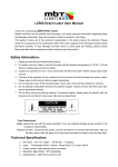
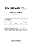
OPERATION AND INSTALLATION MANUAL TM Expansion Pro Analyzer 2000 Filter Media Depth & Expansion Monitor Rev. 6.0EE Entech Design, Inc. 315 S. Locust Denton, TX 76201 (940) 898-1173 Fax: (940) 382-3242 TABLE OF CONTENTS 1. PRODUCT DESCRIPTION .............................................................................. 4 2. APPLICATIONS ................................................................................................ 6 3. FEATURES ........................................................................................................ 7 3.1 MULTIPLE TRANSDUCER, MULTIPLE MEASURE POINT UNIT ... 7 3.2 PROGRAMMING ................................................................................... 7 3.3 DISPLAY................................................................................................. 7 3.4 CONFIGURATION................................................................................. 8 3.5 MEASUREMENT LIMIT......................................................................... 8 3.6 TEMPERATURE .................................................................................... 8 3.7 MATERIALS OF CONSTRUCTION..................................................... 8 3.8 4 TO 20 mA OUTPUTS ......................................................................... 8 3.9 RS232 INTERFACE .............................................................................. 8 3.10 ECHO LOSS ALARM RELAYS .......................................................... 8 4. POWER, WIRING & CONNECTIONS............................................................. 9 4.1 POWER REQUIREMENTS .................................................................. 9 4.2 TRANSDUCER WIRING ....................................................................... 9 4.3 CUSTOMER CONNECTIONS ............................................................ 10 4.3.1 TRANSDUCERS ..................................................................... 11 4.3.2 POWER CONNECTIONS ...................................................... 12 4.3.3 ECHOL LOSS ALARM RELAYS ........................................... 12 4.3.4 CURRENT LOOP OUTPUTS AND SERIAL PORTS .......... 13 4.3.5 GENERAL CONNECTION RECOMMENDATIONS............. 14 5. CONTROL PANEL & DISPLAY VIEWS........................................................ 15 5.1 GRAPHICAL TYPE DISPLAY ............................................................ 15 5.1.1 MEDIA EXPANSION VIEW ................................................... 15 5.1.2 MEDIA DEPTH VIEW ............................................................. 16 5.1.3 ECHO WAVEFORM VIEW .................................................... 16 6. INSTRUMENT PROGRAMMING ................................................................... 17 6.1 CONTROL PANEL KEYPAD .............................................................. 17 6.2 MENU ORGANIZATION AND NAVIGATION.................................... 17 6.2.1 ACCESS TO FACTORY SETTINGS .................................... 17 6.2.2 ACTIVATING MENU LOCKOUT ........................................... 18 Page - 2 6.3 MENU ORGANIZATION & PARAMETERS....................................... 18 6.3.1 SYSTEM................................................................................... 18 6.3.2 PARAMETERS........................................................................ 19 6.3.3 ECHO LOSS ALARM RELAYS ............................................. 21 7. 4-20 mA OUTPUT FUNCTION........................................................................ 22 7.1 ESTABLISHING THE 4-20 mA PROPORTIONAL SPAN…………….22 7.2 ESTABLISHING 4-20 mA SET POINTS ……………………………….22 7.2.1 4 mA SET POINT .................................................................... 22 7.2.2 20 mA SET POINT................................................................. 23 7.3 RE-SPANNING THE 4-20 mA PROPORTIONAL SPAN............... 23 8. MAINTENANCE ............................................................................................... 24 8.1 PREVENTATIVE MAINTENANCE..................................................... 24 9. WARRANTY..................................................................................................... 25 9.1 ONE YEAR PRODUCT WARRANTY ................................................ 25 10. INSTALLATION & OPERATION.................................................................. 26 10.1 INSTALLATION ................................................................................. 26 10.1.1 PROCESSOR INSTALLATION........................................... 26 10.1.2 TRANSDUCER INSTALLATION......................................... 26 10.2 START-UP AND OPERATION......................................................... 26 10.2.1 START-UP ROUTINE........................................................... 26 10.2.2 OPERATION ......................................................................... 30 10.2.3 RE-START FROM REBOOT COMMAND .......................... 31 10.2.4 SYSTEM CALIBRATION ..................................................... 31 Page - 3 1. PRODUCT DESCRIPTION Expansion Pro Analyzer 2000 is a special purpose instrument designed to provide accurate and repeatable measurements in granular media gravity filters. During normal filter operation, Media Depth and Change in Media Depth are recorded and viewed in a convenient chart-style display. During active filter backwashing, Media Expansion is measured and displayed in both units (in. or cm) and as a percent of Media Depth for effective process control. This is a limited range instrument that is suitable for application in most large-scale water treatment and wastewater treatment filters. The effective measurement range is one (1) to seven (7) feet from the transducer. Expansion Pro Analyzer accepts up to four sensor inputs for automatic sequential monitoring of media in multiple filters. Multiple sensors may be located in a single filter to secure valuable information on the consistency of flow across the filter. This instrument is a microprocessor based, echo-time measuring device. Acoustic impulses emitted from a transducer are reflected back from the media and the transit time from generation to echo is measured. The elapsed time is proportional to the distance between the transducer and media, producing an accurate Range to Target distance measurement. This Range measurement is then referenced to the user established Media Depth such that changes in the Range measurement are reported as equal and opposite changes in Media Depth and Media Expansion. Page - 4 Change in Range produces equal but opposite change in Media Depth Range Instrument Measurement Media Depth Referenced Measurement Value Fig. 1 Automatic initialization, calibration and parameter setting features make this instrument very simple to set up and operate. This is a non-contact continuous measurement device that is essentially maintenance free. Operator Interface, System Display & Outputs: • Membrane switch control panel & intuitive menu system • Backlit graphical LCD with multiple user screen VIEWS • Four (4) isolated 4-20 mA outputs • Four (4) 10 Amp SPDT Echo Loss Alarm Relays • RS 232 communications with user supplied PC or laptop computer and WinBin© Data Logging Software. Page - 5 2. APPLICATIONS Expansion Pro Analyzer is designed for application in gravity filters typically found in municipal and industrial water and wastewater treatment facilities. These filters are typically constructed of an under-drain system on which layers of rock and gravel support one or two layers of granular media. The filter media typically consists of sand, garnet, anthracite or granular activated carbon – or a combination of these materials. During normal operation, water flows from top to bottom through the filter by force of gravity. The media level (depth) is constant and is generally uniform across the filter. Expansion Pro Analyzer provides a continuous measurement of Media Depth. Impurities that collect in the filter media are removed by a process known as backwashing. Water flow is reversed and impurities are discharged to a wash trough located above the media. The reverse flow of water fluidizes the media and places it in suspension above its normal level. The amount of suspension varies in relation to the water flow rate and other variables associated with the media: type, size, uniformity - and with water temperature. Expansion Pro Analyzer measures and displays the amount of expansion in units (Inches or Centimeters), and as a percent of Media Depth. Loss of media in the wash stream is common. This dynamic occurrence mandates that the zero reference point for expansion measurements be continuously updated while not losing track of the Current Media Depth. Expansion Pro Analyzer maintains correct orientation to these measurement parameters even in the instance of unattended power loss. Page - 6 3. FEATURES 3.1. MULTIPLE TRANSDUCER, MULTIPLE MEASURING POINT UNIT Expansion Pro Analyzer is configured to accept from one to four sensor inputs for location in up to four filters or for additional measurement points in a single filter. 3.2. PROGRAMMING System parameters are entered via a membrane keypad and graphical LCD display. Operating parameters are established at the factory and generally require no site-specific modification. On power-up or Reboot, the Automatic Initialization Routine is invoked. The operator is prompted to enter Media Depth and the Distance From Sensor to Media. The unit then establishes the optimum operating Gain, adjusts Sound Speed, and spans the 4-20 mA current loop output. This routine requires approximately one minute per filter. Expansion Pro Analyzer 2000 is now ready for immediate service. FACTORY settings are not displayed in the menu system unless the valid password is entered and the feature is selected. If desired, the user may also enable a lockout of the menu allowing only personnel who know the user-supplied password to enter the menu system. See sections 6.2.1 and 6.2.2 for a more thorough description of Advanced Settings and Menu Lockout. To ensure all programmed settings remain uncorrupted in the event of a power outage, the system employs non-volatile storage of programmed parameters. No operator intervention is required to recover system settings or stored values that are needed to assure virtually uninterrupted service. 3.3. DISPLAY The system has a graphical display with two measurement Views and one echo waveform View. • Media Expansion View – this View indicates the current Media Expansion measurement in Inches or Centimeters and as a percent of Current Media Depth for a selected filter. • Media Depth View – this View indicates the Current Media Depth and the Change in Media Depth for each filter in chart format. • Echo Waveform View – this View provides a graphic representation of the return echo waveform and signal evaluation parameters. This View is not available Page - 7 unless Factory settings have been enabled. The display is a backlit LCD dot matrix display, with user adjustable contrast. 3.4. CONFIGURATION Expansion Pro Analyzer 2000 accepts from one to four sensors. The unit is supplied with four 4 to 20 mA Outputs and four Echo Loss Alarm Relays. 3.5. MEASUREMENT LIMIT The Measurement Limit is a function of the: 1) Elevation of the transducer above the media, 2) Maximum range measuring capability of the unit (7 ft.), and 3) The Near Zone limitation of the unit (1 ft.). (See 6.3.2.11) The depth of the media does not affect the Measurement Limit. 3.6. TEMPERATURE Operating temperature for the processor is -40°C to +60°C. Transducer is designed for continuous operation in process water at temperature of +1°C to +50° C. 3.7. MATERIALS OF CONSTRUCTION Processor housing: molded fiberglass polyester, NEMA type 4X Transducer: PVC body with epoxy encapsulating potting material 3.8. 4 TO 20 mA OUTPUTS The system is equipped with four internally powered Current Loops, one for each of the four transducer input channels. The Current Loops are protected against transients and reverse polarity. 3.9. RS232 Data logging capabilities are available via RS232 serial connection to a user supplied PC with optional WinBin Data Logging Software package. 3.10. ECHO LOSS ALARM RELAYS The system is configured with four (4) single pole/double throw (SPDT) Echo Loss Alarm relays. Relay ratings are: Nominal switching capacity 10 A @ 250VAC Page - 8 10 A @ 30 VDC Page - 9 4. POWER, WIRING & CONNECTIONS 4.1 POWER REQUIREMENTS AC power requirements are 110/220 (±10%) VAC, 50/60Hz, 100 Watts, switching power supply. Use only copper conductors. There is a 1A Fuse on the Power Supply Board. A user supplied disconnect switch on a separate 15A circuit breaker should be located near the processor unit. The unit is designed for continuous operation. Power line transient protection is provided with Metal Oxide Varistors (MOV), capable of switching in 15ns, and carrying up to 1200 Amps. In the event of a transient that exceeds 275V, these MOVs will cause the fuse to blow. These MOVs have UL and CSA approvals. 4.2 TRANSDUCER WIRING Twenty (20) feet of transducer telemetry cable is supplied with the unit. Belden 9461 Twin Ax shielded cable or equal should be used for additional wiring between the element and the processor if required. The transducer may be located up to 1000 ft. from the processor. CAUTION Take care not to damage the jacket of the telemetry cable upon installation so as to avoid water ingress into the transducer. Page - 10 4.3 CUSTOMER CONNECTIONS POWER SUPPLY BOARD PROCESSOR BOARD LCD CONTRAST ADJUST TRANSDUCER CONNECTOR 1 TX/RX BOARD 12 + GND - + GND - + GND - + GND - 1A FUSE F #1 F #2 F #3 F #4 L G N 3 POWER CONNECTOR 1 RELAY1 RELAY2 1 6 NO NC C NO NC C RELAY3 RELAY4 F #1 1 1 6 NO NC C NO NC C STATUS RELAY CONNECTORS Page - 11 F #2 F #3 F #4 14 VS IO VS IO VS IO VS IO RX TX GD + S - CURRENT LOOP AND SERIAL PORT CONNECTOR 4.3.1 TRANSDUCERS The system will accept up to four (4) transducers. Transducer connections are made to a 12pin PHOENIX type connector. The standard transducer is designed with a ½ " NPT female thread housing to provide for simple attachment to user-supplied conduit. Locate the transducer at least four inches below the top of the wash trough and a minimum of 24 inches above the filter media, ensuring a clear path between the transducer and the media. The transducer should be at least six inches to the side of the wash trough. Installation should be rigid to prevent side-to-side motion. TRANSDUCER CONNECTIONS- PIN PIN # NAME 1 2 3 4 5 6 7 8 9 10 11 12 TRANSDUCER CONNECTION TABLE DESCRIPTION XDCR1POS GND XDCR1NEG XDCR2POS GND XDCR2NEG XDCR3POS GND XDCR3NEG XDCR4POS GND XDCR4NEG Connect to transducer positive (clear) Connect to shield Connect to transducer negative (blue) Connect to transducer positive (clear) Connect to shield Connect to transducer negative (blue) Connect to transducer positive (clear) Connect to shield Connect to transducer negative (blue) Connect to transducer positive (clear) Connect to shield Connect to transducer negative (blue) Belden 9461 Twin-Ax cable (or equal) is required for use where additional telemetry cable is required. The transducer shield should be connected to ground only at the processor. Do not ground the shield at any other location, as this may allow a current to flow in the shield and magnetically couple into the transducer leads. Never run signal leads in the same conduit or bundle that carries power wiring, relay coil drives, relay contact leads or other high level voltages or currents. If possible, avoid mounting the processor near high voltage sources such as breakers, fuse Page - 12 block, or terminal strips. Avoid magnetic field sources such as large transformers, motor control relays or motors. 4.3.2 POWER CONNECTIONS Power connections are made to a three position Phoenix type connector. The power connector is not a removable connector. PIN # PIN NAME 1 2 3 L/L1 G N/L2 POWER CONNECTION TABLE (JP5) DESCRIPTION LIVE GROUND NEUTRAL 4.3.3 ECHO LOSS ALARM RELAYS The system is equipped with 4 contact relay devices to alarm loss of echo. Connections are made with two 6 position PHOENIX type connectors as show in the following table. Relay ratings are: Nominal switching capacity 10 A @ 250V AC 10 A @ 30 V DC RELAY BANK 1 CONNECTION TABLE (JP3) PIN # 1 2 3 4 5 6 PIN NAME RELAY 1 RELAY 1 RELAY 1 RELAY 2 RELAY 2 RELAY 2 NORMALLY OPEN NORMALLY CLOSED COMMON NORMALLY OPEN NORMALLY CLOSED COMMON Page - 13 RELAY BANK 2 CONNECTION TABLE (JP7) PIN # 1 2 3 4 5 6 PIN NAME RELAY 3 RELAY 3 RELAY 3 RELAY 4 RELAY 4 RELAY 4 NORMALLY OPEN NORMALLY CLOSED COMMON NORMALLY OPEN NORMALLY CLOSED COMMON For typical Echo Loss Alarm functioning, connect the alarm device to NORMALLY OPEN and COMMON pin positions. Connection to NORMALLY CLOSED and COMMON will result in relay closure during normal instrument measurement and opening during periods of echo loss. See Section 6.3.3.2 of this manual for a description of Echo Loss Alarm functioning and instrument settings. 4.3.4 CURRENT LOOP OUTPUTS AND SERIAL PORTS 4.3.4.1 Current Loops The system is equipped with four Isolated 4-20 mA current loops capable of operating into a load impedance of 250Ω, one current loop for each of the four transducers. If the recording or monitoring device is not designed for this impedance, the 4-20mA output signal may be adversely affected. Connections are made to a 14 position PHOENIX type connector which also has connections for a Non Isolated RS232. Reverse polarity protection is provided. Supply Voltage: The current loops are internally powered. 4.3.4.2 RS232 The RS232 is intended for applications where there are short connections between the processor and the computer. There is no isolation and no transient protection. CAUTION Do not use the RS232 in environments where there is a possibility of large voltage transients. If voltage transients are present, the RS232 wires should be placed in a grounded conduit. Page - 14 4.3.4.3 Current Loop, RS485, RS232 Connection Table (JP2) PIN PIN # NAME DESCRIPTION 1 2 3 4 5 6 7 8 9 10 11 12 13 14 4-20mA Current loop - Positive Loop current - Negative 4-20mA Current loop - Positive Loop current - Negative 4-20mA Current loop - Positive Loop current - Negative 4-20mA Current loop - Positive Loop current - Negative RS232 Receive RS232 Transmit RS232 Ground (non isolated) LOOP1 VS LOOP1 IO LOOP2 VS LOOP2 IO LOOP3 VS LOOP3 IO LOOP4 VS LOOP4 IO RS232 RX RS232 TX RS232 GND RESERVED RESERVED RESERVED 4.3.5 GENERAL CONNECTION RECOMMENDATIONS Wires should be stripped to a length of 0.310". Recommended terminal screw fastening torque is 7 in-lbs. Recommended wire size range: AWG #12 stranded or AWG 14-26 stranded and solid. Cables should be run in a dedicated grounded metal conduit with no other cables. Page - 15 5. CONTROL PANEL & DISPLAY VIEWS The front control panel is equipped with four (4) membrane keys and an LCD display area. 5.1 GRAPHICAL TYPE DISPLAY The graphic LCD provides three informational VIEWS and allows the user to configure the system by accessing a descriptive, alpha-numeric menu system. Display VIEWS are selected by pressing the SCROLL key causing the optional VIEWS to loop into view. The Echo Waveform View is not available unless FACTORY settings have been turned ON. The menu system is accessed by pressing the NEXT key. 5.1.1 MEDIA EXPANSION VIEW This VIEW displays the current Expansion measurement in units (in, cm) and as a percent of Current Media Depth for a single filter. If additional Filters are activated in the SYSTEM MENU, the unit will automatically sequence through all Filters. The display time for each Filter is determined by the Cycle Time and Refresh Rate settings. Default Factory Settings provide approximately six seconds of measurement updating per filter in sequential mode of operation. Page - 16 5.1.2 MEDIA DEPTH VIEW This VIEW displays the Current Media Depth and change (∆) in Media Depth for all filters in chart form. The arrow (↓) symbol above the filter number indicates the filter in which a measurement is currently being updated. This View does not reflect Media Expansion during filter backwashing. 5.1.3. ECHO WAVEFORM VIEW This VIEW provides a graphical representation of the return echo waveform for an individual filter in terms of echo strength (dB) in relation to time/distance. This VIEW is only available with Factory Settings ON. Page - 17 6. INSTRUMENT PROGRAMMING All required system parameters are either pre-programmed at the factory or will be prompted for entry during the Automatic Initialization routine. However, field adjustment of operating parameters are easily made by accessing the on board menu system. The following section describes how to navigate the menu system and select program parameters. 6.1. CONTROL PANEL KEYPAD The control panel on the front of the processor contains four (4) membrane buttons or Keys and the LCD display. Key functions are described below. The buttons and their basic functions are: HOLD: Press to select and hold a filter for continuous measurement updating during backwash. Press again to release the Hold function and return to sequential operation. The unit will automatically release the Hold function after approximately one hour if left unattended. SCROLL: Press to scroll Menu listings from bottom to top and to change a parameter value. Parameter values increase until the maximum value is reached and then loop to the minimum value. The Scroll key is also used to select the current display View. NEXT: Press to enter the Menu system and to advance in the Menu hierarchy. If pressed and held while cycling power, settings held in non-volatile RAM memory are cleared and Factory settings are recalled. ENTER: Press to confirm and save a parameter value that has been changed. 6.2. MENU ORGANIZATION AND NAVIGATION When power is applied to the unit, the system initializes with parameters that are stored in nonvolatile memory. Factory settings are not displayed in the Menu and are password protected. 6.2.1 Access to Factory Settings Factory Settings may be accessed by selecting this Menu path and entering the required symbolic password. To turn Factory Settings ON, press ENTER after scrolling to each of the following symbols: , ♥ , . Advance to the ON/OFF view by pressing NEXT. Press SCROLL to highlight ON, and then press ENTER. All system parameters Page - 18 may now be viewed and updated in the Menu System and the graphical Waveform Display is viewable. CAUTION: Factory Settings generally do not require field modification. Adjustments to these settings without the assistance of an authorized service technician is not advised. For assistance, call Customer Service at 940-898-1173. 6.2.2. ACTIVATING MENU LOCKOUT The user can enable a lockout allowing only personnel who know the user-supplied password to enter the menu system. To enable, highlight the Menu Lockout option and press NEXT. Then scroll to ON and press ENTER. The user is then prompted to SET a password using a three position symbol based screen. Using the UP or DOWN key, scroll the first position to the desired symbol and press ENTER. Scroll the second and third positions similarly. Note: The Password may only be overridden by recycling power to the unit while depressing the ENTER key. System parameters will revert to Factory Settings. Application specific parameters must be reentered manually. 6.3. MENU ORGANIZATION & PARAMETERS 6.3.1. System 6.3.1.1 Units The options for Units are: cm, in. This parameter establishes the desired units of measure for system displays and outputs. Once established, the selected Unit applies uniformly throughout all system settings, displays and outputs. The established Units apply globally for all Filters. Select and enter the desired units of measure based on user preference. 6.3.1.2 Number of Filters The options for No. of Filters are: 1, 2, 3, 4 This parameter establishes the number of transducers operated by the analyzer. Select and enter the correct number of transducers. 6.3.1.3 Rename Filters Page - 19 This function allows the user to re-establish the two-character identifier for each available filter. The user will be prompted to select the desired Alpha/Numeric characters for each filter (sensor). 6.3.2. Parameters This menu path provides access to parameters that apply for each Filter individually. Upon entry into the Parameters menu, the user is prompted to select a Filter. Scroll to the desired Filter number and press NEXT to proceed. 6.3.2.1 Media Depth The range of values for Media Depth is: 0 to 120 in. (305 cm) Factory Default: 0 Media Depth is a baseline value that is provided by the user. EPA 2000 Range measurements are referenced to Media Depth in a manner such that changes in the measured Range (distance from the sensor to the surface of the media when the filter is on-line) are reflected as equal but opposite changes in Media Depth. 6.3.2.2 Refresh Rate The range of values for Refresh Rate is: 2, 4, 6, 8, and 10 (seconds) Factory Default: 2 Refresh Rate determines that amount of signal data that is evaluated and the corresponding approximate amount of time required to refresh the current measurement. 6.3.2.3 Cycle Time The range of values for Cycle Time is: 3 – 100, and 0 Factory Default: 3 Cycle Time establishes the number times that the measurement is refreshed for a Filter before sequencing to the next filter. The amount of time allocated to a Filter is determined by the Cycle Time and Refresh Rate settings. If Cycle Time is set to 0, the filter is bypassed. Page - 20 6.3.2.4 Gain Set Point The Range for Gain Set Point is: 10 to 50 Factory Default: 35 Gain Set Point determines the level of signal amplification that Automatic Gain seeks. Increase the parameter to cause the unit to seek a higher level of signal amplification and lower it to produce the opposite effect. 6.3.2.5 Dampening The range for Dampening is: 1 to 10 Factory Default: 2 Dampening controls how quickly changes in underlying range measurements will be reflected in changes in system output values. A setting of 1 will produce an immediate response to changes in range values but may produce a somewhat unstable measurement result. Higher settings will provide a smoother, more stabile measurement progression during filter backwashing but may result in a lag in measurement behind the rapidly expanding media. 6.3.2.6 Gate-L The range for Gate-L is: 0 to 120 Inches Factory Default: 12 This parameter establishes the left-side (upper) boundary of an area of tracking emphasis (Gate) around the current media interface location. 6.3.2.7 Gate-R The range for Gate-R is: 0 to 120 Inches Factory Default: 24 This parameter establishes the right-side (lower) boundary of an area of tracking emphasis (Gate) around the current media interface location. 6.3.2.8 Gate Rate The range for Gate Rate is 1 to 50. Factory Default: 1 Page - 21 Gate Rate determines how quickly Gate-L will open to allow tracking to an interface that is outside of the Gate. 6.3.2.9 Reboot This function re-calls the Automatic Initialization routine and prompts the user to re-establish the: 1) Distance from the transducer to the media, and 2) Media Depth. All other system parameters remain unchanged. The following activities occur during Reboot: • System operating Gain is calculated and established. • The unit re-calibrates Sound Speed based on the entered: Distance From Sensor to Media. • Range is referenced to the entered Media Depth. • Current Media Depth register is reset to the entered Media Depth. • The Change in Media Depth register is set to zero (0). • 4-20 mA span is reset to ± 2 ft. of Media Depth. User must reconfigure the expected span in input control devices. NOTE: If REBOOT is called for the purpose of calibrating the unit, an accurate dimension must be entered when prompted to Enter Distance From Sensor to Media. Failure to enter a correct dimension will result in faulty calibration and inaccurate measurements. 6.3.2.10 Near Zone This parameter sets the blanking zone near the transducer. The range for Near Zone is 1 ft. to 7 ft. Factory default is 1 ft. 6.3.3 Echo Loss Alarm Relays Relays can be used with auxiliary devices to alarm the user that there is insufficient echo to secure a dependable measurement. Echo loss may occur as a result of certain normal process conditions, certain abnormal process conditions or as a result of instrument failure or incorrect installation, connection or set up. Following are examples of these types of alarm conditions: Alarm Due to Normal Process Condition – Echo is not present when the Page - 22 transducer is not submerged in water. Typical filter backwash routines involve lowering the water in the filter below the elevation of the transducer to perform surface washing and scouring routines in preparation for backwashing. Depending on the selected alarm Delay setting, this condition will activate the alarm relay. Alarm Due to Abnormal Process Condition – Air may collect in the filter media bed over time and release gradually while the filter is online or suddenly and aggressively during the course of filter backwashing. Air bubbles that collect on the face of the transducer may result in echo loss and activate the alarm relay. Typical air scouring that is discontinued during the early stages of a wash cycle is not expected to activate the alarm relay. The Delay parameter setting may be increased if necessary to prevent an undesired alarm. Alarm Due to Instrument Failure, Incorrect Installation or Connection – Loss of echo may result from certain types of hardware failures or cabling and connection problems. 6.3.3.1 Delay The Delay parameter establishes the amount of time that the Echo Loss condition must persist for the Echo Loss Alarm Relay to activate. The range for Delay is: 2 – 120 Seconds Factory Default: 2 Seconds 7.0 4-20 mA Output Function 7.1 Establishing the 4-20 mA Proportional Span The analyzer automatically provides a 4-20 mA signal that is proportional across a four ft span. The span is centered at the MEDIA DEPTH that is established by the user when the system is initialized. After the unit is initialized, it will generate a signal of 12mA that is associated with MEDIA DEPTH. The user is not required to establish set points in the analyzer for proper operation. 7.2 Establishing 4-20 mA Set Points in the User Control Device (i.e. PLC, DCS, recorder, etc.). 7.2.1 4 mA Set Point Page - 23 Set 4 mA equal to MEDIA DEPTH, minus 24 in. (Ex: If Media Depth = 36 in., 4 mA Set Point = 12 in.) 7.2.2 20 mA Set Point Set 20 mA equal to MEDIA DEPTH, plus 24 in. (Ex: If Media Depth= 36 in., 20 mA Set Point = 60 in.) 7.3 Re-Spanning the 4-20 mA Proportional Span The system automatically re-establishes the 4-20 mA span whenever MEDIA DEPTH is changed by the user. The user must re-establish the 4 mA and 20 mA Set Points as described in 7.2, above. The user may re-establish the MEDIA DEPTH to a new or corrected value at any time by re-initializing with a new MEDIA DEPTH or by entering MEDIA DEPTH in the Parameters menu. Set Points must be re-established in these instances as described in 7.2, above. Page - 24 8. MAINTENANCE 8.1. PREVENTATIVE MAINTENANCE It is recommended that the Transducer face be inspected and cleaned if a buildup of material is noted on the face of the transducer. Clean the transducer by brushing with a nylon bristle brush and a mild detergent. Page - 25 9. WARRANTY 9.1. ONE YEAR PRODUCT WARRANTY Entech Design, Inc. products will be replaced, put in good operating condition, or the purchase price refunded, at the option of Entech Design, Inc., free of charges except transportation, if defective in their manufacture, labeling, packaging, or shipping, and if notice of said defect is received by Entech Design, Inc. within one year from the date of shipment. The cost of such replacement, repair or refund of purchase price shall be the exclusive remedy for any breach of warranty, and Entech Design, Inc. shall not be liable to any person for consequential damages or injury or commercial loss resulting from any breach of warranty of fitness for a particular purpose, and makes no other warranty, express or implied, including implied warranty arising from course of dealing or usage of trade. This is a specific-use instrument designed for application in water and wastewater treatment gravity filters. Use in other applications is not recommended and may not produce the desired measurement results. Page - 26 10. INSTALLATION & OPERATION 10.1 Installation 10.1.1 Processor Installation • The processor may be located inside a building or exposed to the outside environment. Locate processor within 1000 ft. of the transducer(s). • Secure the processor to a wall or instrument panel using the A-48 Mounting Tabs and pan head screws included with the unit. An optional mounting plate assembly is available for handrail mount. 10.1.2 Transducer Installation 10.2 • The transducer housing is designed to accept a ½ inch NPT male thread pipe or conduit. Feed the integral transducer cable through the conduit and tighten by hand until snug. • Position the transducer four inches below the top of the filter wash trough and a minimum of six inches to the side of the trough. Secure the mounting pipe with pipe brackets. An optional mounting bracket assembly is available for handrail mount. NOTE: The transducer must be located below the top of the wash trough to secure expansion measurement during backwash. • Ensure an unobstructed path between the transducer and the filter media. Position the transducer at least two feet above the media. • Ensure that the transducer is mounted perpendicular to the surface of the media and is mounted rigidly to prevent side-to-side movement. Start-up and Operation 10.2.1 Start-up Routine 10.2.1.1 Press and hold the NEXT key while applying or re-cycling power. Release the NEXT key after the LCD energizes. Factory Settings and Parameters will be initialized and stored in memory. Page - 27 NOTE: The transducer(s) must be in place with water at or above the level of the wash trough. Initializing the unit with the transducer out of the water or during backwashing will result in inaccurate system calibration and unreliable measurements. 10.2.1.2 When power is supplied, the unit will run the Automatic Initialization routine. The user will be prompted with the following displays: • Do You Want to Configure the System? DO YOU WANT TO CONFIGURE THE SYSTEM? YES NO Select YES and press ENTER to Customize Filter Names and to enter calibration dimensions. Select NO and press ENTER to accept Filter Names and calibration values that currently exist in the system. IMPORTANT: You must Configure the System on first time start-up or when the sensor has been relocated. • Select the Number of Filters (sensors) in this system SELECT NUMBER OF FILTERS 1 Press SCROLL to select the number of filters (number of sensors: 1, 2, 3, or 4) that are in use with the system. Press ENTER to confirm and advance to the next display. Page - 28 • Customize Filter Names? CUSTOMIZE FILTER NAMES? YES NO Select YES and press ENTER if you want to establish a twocharacter, Alpha/Numeric (0-9 & A-J) identifier for each filter. Select NO and press ENTER to accept the default designations of Filter 01, 02, 03, 04. • Scroll and Press Enter for Filter 1, first character SCROLL AND ENTER FOR FILTER 1 ↓ 01 Press SCROLL to select first character of the Filter Name and press ENTER to select. Scroll sequence is: 0-9, followed by A-J, in continuous loop. • Scroll and Press Enter for Filter 1, second character SCROLL AND ENTER FOR FILTER 1 ↓ 01 Press SCROLL to select the second character of Filter Name and Page - 29 press ENTER to select. Scroll sequence is: 0-9, followed by A-J, in continuous loop. • Distance from Sensor to Media FILTER 01 Enter Distance from Sensor to Media in. 24 Press SCROLL to select the correct dimension and press ENTER to confirm the selection. The scroll sequence is 24-72 in., in continuous loop. IMPORTANT: This dimension is used to calibrate the system. It should be determined from an accurate measurement of the distance from the face (bottom) of the sensor to the top of the filter media with the filter on-line. System measurements will not be accurate if an incorrect dimension is entered. • Media Depth FILTER 01 Enter Media Depth in. 0 Press SCROLL to select the current media depth and press ENTER to confirm the selection. The scroll sequence is 0-120 in., in continuous loop. NOTE: The analyzer does not measure the depth of media in the filter. Page - 30 However, the system accurately measures the distance from the sensor to the top of the media and accurately reflects the Changes in Media Depth and the Current Media Depth. IMPORTANT: Current Media Depth and Percent Expansion measurements, and the automatic ranging of the 4-20mA output, require that the user enter the correct Media Depth during system initialization. After responding to the above Display prompts, the unit will perform the following automatic functions: • Establish the system operating Gain • Calibrate Sound Speed • Enter Media Depth in the Display register for each filter • Re-set the Media Expansion & Change in Media Depth display register to zero • Set the 4-20mA output span to ±2 ft. of Media Depth NOTE: Follow the Start-up Routine (9.2.1) in the event of: 1) First-time start-up or relocation of sensor, 2) Placing a filter in service after an extended outage, or 3) Unit Initialized with the sensor not connected, out of the water, or during a backwash. 10.2.2 Operation 10.2.2.1 Operation with Filter On-Line During on-line filtering, the unit automatically sequences through the established measurement points (1-4 sensors) and continually updates the Current Media Depth and Media Loss registers. The timing of the updating sequence is controlled by the Refresh Rate and Cycle Time parameters. 10.2.2.2 Operation During Filter Backwash When backwashing a filter, the user has the option of two operating modes as described below: Page - 31 10.2.2.2.1 Continuous Sequential Updating. In this mode, the unit is allowed to switch between all available filters. Measurement updating for the filter that is being backwashed occurs intermittently as that filter is reached in the sequence. The effective response time for refreshing the measurement is determined by the Refresh Rate and Cycle Time parameters. 10.2.2.2.2 Filter HOLD for Backwashing The user may isolate a single filter for continuous measurement updating during backwashing. Press the Hold key once, and then Scroll to the desired filter and press Enter. Press Hold again to release and return to sequential operation. The Hold command will release automatically after one hour if the operator does not manually release the Hold. 10.2.3 Re-Start from REBOOT Command The unit may be Re-Initialized by pressing ENTER with the REBOOT command highlighted in the Parameters menu. In this instance, all of the steps described in the Start-up Routine will be conducted, except that the Factory Settings and Parameters will not be re-called. Initialization will occur with the settings in use at the time the REBOOT command is called. 10.2.4 System Calibration 10.2.4.1 Automatic Sound Speed calibration occurs in each of the following instances: • REBOOT command is called by the user • Power is cycled with the NEXT key depressed • User presses ENTER at the prompt: Enter Distance From Transducer to Media. NOTE: Automatic Sound Speed calibration will not occur in the event of an unattended loss of power. 10.2.4.2 Calibration involves comparing the instrument Range measurement to the dimension entered at the prompt: Enter Distance From Sensor to Media. The underlying Sound Speed assumptions are adjusted to Page - 32 agree with this known distance. NOTE: The user must enter the correct distance from the transducer to the media for accurate calibration. 10.2.4.3 Seasonal re-calibration may be necessary to correct for significant changes in filter water temperature. 10.2.4.4 It is not necessary to re-calibrate when the user changes the Media Depth parameter in the menu. Current Range measurements are referenced to the new Media Depth value and future measurements correctly reflect this adjustment. Page - 33