1
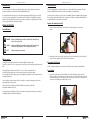
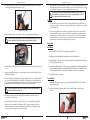
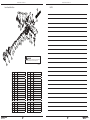
SERVICE INSTRUCTIONS
GEMINI BREATHABLE INFLATOR
SR9000
www.sherwoodscuba.com
www.sherwoodscuba.com
INTRODUCTION
General Procedure
The instructions set forth in this document are intended to guide the experienced scuba equipment repair technician
through the standard service procedure for the Gemini Breathable Inflator (Gemini).
The Gemini Breathable Inflator is a multifunctional device for use with a standard buoyancy compensator. The Gemini
replaces the standard inflator and combines in the same unit an alternate second stage regulator.
It is assumed that the technician possesses basic scuba equipment repair training and the skill necessary to perform the
service. If you have not received regulator service training as an Authorized Sherwood Scuba Dealer do not attempt to
perform the service described in this document. If you are uncertain as to whether you are qualified to perform this service
contact your regional Sherwood Scuba Distributor for advice.
Servicing the Gemini is similar to the service procedures for a standard BC inflator and a standard second stage regulator.
There are three functional modules within the Gemini consisting of the oral inflator, power inflator and demand valve. It is
recommended that these be serviced in the order presented.
GENERAL INSTRUCTIONS
Separate the Gemini from the BC
1. Snip the two plastic tie wraps that secure the Gemini to the BC airway hose taking care not to puncture
the hose.
Special Notations
!
WARNING: Indicates a potentially hazardous condition or situation which, if not avoided, may
result in serious injury or death.
!
CAUTION: Indicates a potentially hazardous condition or situation which, if not avoided, may
result in minor injury. It may also be used to alert against unsafe practices.
NOTE:
Indicates an important point or reminder.
Cut with wire pliers.
2. Separate the hose from the Gemini body to expose the wire loop. Push the retaining pin (32) out sufficiently to slip
the wire off the pin, separate the Gemini from the BC and set the BC aside.
When to service
Generally the Gemini should be inspected for service at least annually. If the regulator has been
subjected to less than 200 hours of use it may just require a routine inspection not necessarily requiring the replacement of
parts.
If the regulator has been subjected to more than 200 hours of use or it has not received the benefit of
careful post-dive cleaning and storage in a clean environment, the regulator should receive standard
service. Standard service includes cleaning, inspection for damaged parts, replacement of certain seals and the valve seat,
reassembly and adjustments.
Gemini units that are subjected to extreme conditions such as daily use or infrequent cleaning may need service more
frequently depending on inspection results.
Disassembly of the Gemini
In order to simplify reassembly, keep the components removed from each module separated for easy identification.
Power Inflator
1. Locate the power inflator valve cap (8) on the backside of the Gemini and unthread it using the special tool
(TL9000) or needle nose pliers to apply torque to the cap. Inspect the cap O-ring (6) and remove any sand or other
deposits that might be present. If it is necessary to remove the O-ring to clean it, use a soft tool such as a plastic or
wooden pick to avoid damage to the sealing surfaces on the cap.
Sherwood Scuba offers a standard service kit (P/N 9000-PK) that contains the parts that should be
replaced at the standard service interval.
Use only authorized parts and lubricants. Substitution of parts and or lubricants may cause the product not to perform as
intended by the manufacturer and will void the warranty.
Use special tool or needle nose pliers.
2
3
www.sherwoodscuba.com
2. Remove the Power Inflator Poppet (7) using a flat blade screwdriver. Remove and discard the poppet
seal O-ring (4).
www.sherwoodscuba.com
Demand Valve Assembly
1. Remove the Gemini cover (31) as follows: Inspect the rim of the cover on the backside of the Gemini to locate the
small opening provided to allow insertion of a small screw driver.
Use small flat blade screwdriver.
3. Slide the Power Inflator stem out of the body. Remove and discard the shaft seal, O-ring (4).
Locate notch in cover and use a small
flat blade screwdriver.
2. With the tip of the screwdriver inserted approximately ½ inch under the rim of the cover and against the outside
perimeter of the Housing (1), slide the screwdriver tip toward the small end of the cover until it can be pushed up
and through the vent hole in the cover. The tip of the blade should extend above the surface of the cover by at
least 1 inch.
Use special tool or needle nose pliers.
4. Remove the Power Inflator Retainer (5) using special tool (TL9000) or needle nose pliers to apply torque. Remove
and clean the O-ring (6). Set aside for reassembly.
Oral Inflator
Slide blade 90˚ as shown.
1. Locate and remove the Exhaust Valve Cover (17). You should be able to torque the cover sufficiently using your
fingers, but if necessary pliers with padded jaws (taped) may be used to gently remove the cover.
3. Pry upward with the screwdriver handle and the rim of the cover will disengage the housing.
2. Lift out the Exhaust Valve Assembly (15 & 16). It is not necessary to remove the Exhaust Valve (16) from the
Exhaust Valve Base. Simply clean any deposits from the valve surfaces and inspect it for damage.
Replace the valve if it is damaged.
3. Use a ¼“ nut driver to remove the lock nut (14). Set aside the locknut and washer for reassembly.
4. Remove the Oral Inflator Seal (13) and wipe clean to remove any deposits. If the seal is damaged replace it. It is
normal for a seating ring (depression) to be present. This should not be mistaken for damage.
5. Remove the Oral Inflator Button and stem. Remove and discard the Oral Inflator shaft seal, O-ring (12). Set aside
Spring (10) and Washer (11) for reassembly.
Gently pry.
4. Lift out the Diaphragm Retainer (30) and Diaphragm (29).
4
5
www.sherwoodscuba.com
5. Locate the male end of the quick-connect portion of the installed Regulator Valve Body (20) and use a flat blade
screwdriver to lift and remove the Retaining Ring Cover (18).
www.sherwoodscuba.com
13. Inspect the mouthpiece (34) for signs of damage. It must be free of cuts and nicks that might allow water to pass
between the mouthpiece and the housing when installed. It is not necessary to remove the mouthpiece for cleaning
if it is undamaged. If replacement is necessary, snip and discard the tie wrap to remove.
Note: All O-ring seals should be cleaned and then lightly lubricated with Crysto- Lube MCG 111
before installation. Dow Corning 111 Silicone Grease is an acceptable substitute, but the use of
silicone spray and other lubricants should be avoided.
Cleaning
1. Unless the Gemini has been subjected to harsh conditions cleaning generally may be accomplished with a soft
brush and soapy warm water. Be certain to rinse completely with fresh water. Prolonged exposure to soap residue
can be damaging to seals.
Use small flat blade screwdriver.
6. Remove the Retaining Ring (19) using a flat blade screw diver to pry the Retaining Ring radially outward.
Note: Some models of the Gemini have a Set Screw located inside the Housing (1). This Screw
must be removed before the Valve Set Assembly can be separated from the Housing.
2. The Gemini housing material has been selected for its properties that resist adhesion of deposits but if mineral
deposits become difficult to remove you may soak the rigid synthetic and metallic parts (everything except the Oring seals) in a dilute acidic solution comprised of 50 % white vinegar and 50% water. Use of ultrasonic cleaning
solutions should not be necessary. If such solutions are deemed necessary, to accelerate cleaning be certain to
verify with the solution supplier that it is compatible with respiratory equipment.
Reassembly
Oral Inflator
1. Install the Oral Inflator shaft seal (12) in the housing and cover with Washer (11)
2. Install spring (10) and Oral Inflator Button by gently passing the stem through the shaft seal.
3. Install the Oral Inflator Seal with the conical surface facing toward the housing. Install Washer (28) and secure with
the lock nut (14) Finger tight is sufficient.
7. The Demand Valve Assembly will now slide out of the Housing with a gentle push against the end of the male quickconnect.
4. Install the Exhaust Valve Assembly (15 & 16). If these parts were separated be certain to fully engage the Exhaust
Valve stem in the Exhaust Valve Base by stretching and pulling the tail of the valve stem as it is inserted in the base.
Test the valve by gently pulling in the opposite direction of installation to be certain it is securely retained.
8. Separate the Demand Valve Assembly by loosening the threaded connection between the Lever Support (26) and
the Regulator Valve Body (20).
5. Install the Exhaust Valve Cover finger tight.
9. At this point the Regulator Poppet (24), Regulator Spring (25), Demand Lever (27), Lock nut (14), Washer (28) and
Lever Support (26) will remain together as a subassembly. If this subassembly is free of deposits and allows the
Poppet to move freely when the Demand Lever is actuated, it is not necessary to further disassemble. However the
subassembly should be flushed and rinsed and the L.P. Seat should be removed and discarded.
Note: The Demand Valve is spring loaded. Be prepared for sudden release and separation of
the parts when the lock nut is removed.
Power Inflator
1. Install the static seal (6) in the housing and secure by inserting the Power Inflator Retainer (5). Use needle nose
pliers to torque finger tight.
2. Install a new shaft seal (4) onto the Power Inflator (2) stem. Be certain that the seal is located in the groove
on the stem.
10. If the presence of deposits requires further disassembly of the Demand Valve for adequate cleaning, use
a ¼” nut driver to remove the lock nut.
11. Inspect the Regulator Valve Body seals, O-rings (6) for deposits. Clean as necessary. Replace damaged seals.
12. Inspect the Seat Crown for damage to the seating surface. Nicks or gouges on the seating surface indicate
damage. If damage is present it cannot be repaired and must be replaced. Remove and discard O-ring (21).
Clean the Seat Crown of any deposits and set aside for reassembly.
Slide O-ring over shaft and seat in groove.
6
7
www.sherwoodscuba.com
3. Install the spring (3) and pass the Oral Inflator stem though the housing.
www.sherwoodscuba.com
3. Note that the curvature of the Demand Lever is toward the indexing tab on the Lever Support when
correctly oriented.
4. Install the O-ring (21) on the Seat Crown (22) and install the Seat Crown into the Regulator Valve Body.
5. Install a new L.P. Seat (23) into the Regulator Poppet (24).
Note: The proper tightening of the Lever Support to the Regulator Valve Body is necessary to
ensure the regulator remains in adjustment. Use a properly calibrated torque wrench suitable
for applying measured torque specified at 15 in-lbs. Do not tighten in excess of 20 in-lbs.
Excessive torque will damage the Lever Support and require replacement.
4. Place the poppet seal, O-ring (4) over the threaded end of the Power Inflator Poppet (7). It is not necessary to seat
the O-ring in the Poppet. This will occur when the Power Inflator is fully assembled. Assemble the Power Inflator
Poppet onto the stem. Finger tight is sufficient.
6. A. Insert Lever Support (26) into the Gemini Socket Tool (10-100-90) aligning the slot in the socket with the index
tab on the Lever Support.
B. Insert a small probe into the air exit hole in the Regulator Valve Body (20) to create a means to grasp and
stabilize the subassembly for tightening.
C. Tighten to 15 to 20 in-lbs torque.
5. Replace the static seal, O-ring (6) on the Power Inflator Valve Cap and thread the cap into the housing. Use needle
nose pliers to fasten hand tight.
Demand Valve Reassembly
If the Demand Valve Subassembly was not disassembled proceed to step 4:
1. Use the Regulator Valve Body (20) as a fixture to aid with the insertion of the Regulator Poppet (24) into the Lever
Support (26). Place the Valve Body on a flat surface with the quick connect end projecting upward.
2. Place the Spring (25) and the Regulator Poppet (24) in the Lever Support (26) and compress this combination
against the Valve Body, taking care to align the square feature on the Poppet with the square hole in the Lever
Support. Continue to compress the Spring until the threads of Regulator Poppet project sufficiently to allow the
Demand Lever (27), Washer (28) and the Lock Nut (14) to be installed. Install the Lock nut just enough to hold the
assembly together with the threads even with the outer surface of the Lock nut. The lock nut will be tightened further
during final adjustment.
7. Replace O-rings (6) on the Regulator Valve Body.
Install lever curved end towards lever support index
8
8. Install the Demand Valve Subassembly into the housing making certain that the indexing tab on the Lever Support
aligns with the mating feature in the Housing. Press together until the Demand Valve Subassembly is fully seating
and the groove for accepting the Retaining Ring is clearly visible.
9
www.sherwoodscuba.com
9. Replace the Retaining Ring (19) in the groove on the Valve Body to secure it in the housing.
10. Replace the Retaining Ring Cover (18) using a blunt tool to seat it fully against the housing.
11. Some models of the Gemini have a Set Screw located inside the housing. If this Set Screw was removed during
disassembly, replace it and tighten until snug.
Regulator Adjustments
www.sherwoodscuba.com
11. Orient the Cover (31) so that the logo is properly aligned when viewing the face of the regulator with the
mouthpiece at the left.
12. Match the groove in the cover with the rib on the outside of the Housing and snap the cover into place. Starting at
the small end of the cover and advancing toward the opposite end simplifies this procedure.
13. Operate the Power Inflator and Oral Inflator buttons to verify the system operates without leakage.
14. Replace the mouthpiece if it was removed securing with a cable tie.
1. The Gemini must be supplied with intermediate pressure before the demand lever height can be properly adjusted.
2. Inspect the Gemini supply hose with the quick-connect fitting (35) for evidence of damage before applying pressure.
Slide the hose protector back at the first stage end of the hose to inspect the hose near the fitting. If the hose is cut
or torn it should be replaced.
3. If the hose was removed from the first stage, inspect the O-ring at the threaded end of the hose for damage.
Replace damaged O-rings. Connect the hose to a low pressure port on the first stage and torque hand tight
(approximately 40 in-lbs)
4. Connect the first stage to an air supply and apply at least 500 PSI. Check the hose for leaks. If there is leakage from
the quick–connect fitting refer to Appendix A for instruction.
5. The Gemini is designed to operate with an intermediate pressure of 125 to 155 PSI. If you suspect that the first
stage coupled with the Gemini supplies an intermediate pressure outside this range then the first stage should be
serviced or replaced.
15. Reinstall the Gemini on the BC airway using reverse procedure from removal. Secure with two tie wraps.
INSPECTION
Operate the oral inflator to check for opening and resealing.
1. Connect the supply hose to apply intermediate pressure to the Gemini, Operate the power inflator to verify that it
will inflate and return to the closed position without leaking. Submerge the Gemini to check for leakage.
2. Attach the Gemini to the BC airway using the reverse procedure of removal and secure with two cable ties. Be
certain that loop in the airway cable engages the pin at the end of the Gemini. Test the power inflator again to
observe inflation of the BC. Deflate the BC by pulling the cable to operate the valve at the upper end of the airway.
Note some model BCs may not have the cable operated valve feature.
APPENDIX
Gemini Hose with Quick-Connect
The Gemini hose is not included in the standard service procedure because it seldom requires attention. If a leak in the
hose assembly is detected the hose may be serviced as follows:
1. Remove the Quick-Connect fitting from the hose using two wrenches to separate the assembly. Remove and replace
the O-ring (part number 010B) in the swivel end of the hose fitting using a wooden or plastic pick to avoid damage
to the metallic sealing surfaces.
Lever height adjustment even with edge of housing
6. Connect the Gemini to the supply hose. This may be done with or without pressure applied to the hose.
7. Use a ¼“ nut driver to rotate the Lock Nut clockwise adjusting the demand lever upward until all of the play between
the Lever and the Poppet Assembly is removed. Do not tighten beyond this point as this will preload the valve
assembly and may cause it to leak when the regulator is completely assembled. The demand Lever should align with
the surface of the Housing and not fall more than 1/8” inch this point. If the Demand Lever is above the surface of
the housing or more than 1/8” below it, the Demand Lever is distorted or improperly installed. Replace if distorted.
2. Join the Quick-Connect to the hose fitting using two wrenches to secure. Torque to approximately 40 in-lbs or
hand tight.
3. Apply pressure to the hose and check for leaks. Generally the replacement of the O-ring as described in Step 2 will
resolve leakage. If leakage has not been resolved the internal seals in the Quick-Connect fitting may be the cause.
Further service to the Quick-Connect requires return to your Regional Distributor.
8. If the Poppet does not fully seat (slight leak), disconnect the supply hose and use a 3/16” hex wrench to adjust the
Seat Crown (22). Access to the Seat Crown is through the quick- connect end of the Regulator Valve Body. Adjust
to advance the Seat Crown forward by rotating it ¼ turn. Reconnect the hose to apply pressure. If leakage persists
repeat above procedure and rotate Seat Crown inward an additional ¼ turn. Do not adjust further. If leakage
persists, the cause is likely from a damaged seating surface on the Seat Crown, a damaged surface on the L.P. Seat
or an intermediate pressure greater than 155 PSI. Readjust the Lock Nut to remove play.
9. Inspect the Diaphragm (29) for pin holes or other damage. Replace if any damage is present.
10. Install the Diaphragm into the Housing and install the Diaphragm Retainer (30).
10
11
www.sherwoodscuba.com
www.sherwoodscuba.com
Gemini Breathable Inflator
NOTES:
35
17 16 15
8
6
7
34
32
18
19
33
4
6
14 28
5
4
13
3
2
20
21
22
6
6
1 12
11
24 23
25
27
10
9
26
28
14
29
WARNING
Use only Sherwood Scuba parts! Use of other manufacturer’s parts will void all warranties
and could result in air delivery failure, causing serious personal injury or death.
30
31
070914
ITEM
PART #
DESCRIPTION
ITEM
PART #
DESCRIPTION
1
9000-1
Housing
19
9000-46
Retaining Ring
2
9000-2
Power Inflator Button Assembly
20
9000-8
Regulator Valve Body
3
9000-52
Spring
21
010B
4
006B
O-ring
22
9000-17
Seat Crown
5
9000-22
Power Inflator Retainer
23
9000-14
L.P. Seat
6
016B
7
9000-21
O-ring
O-ring
24
9000-19
Regulator Poppet
Power Inflator Poppet
25
9000-51
Spring
8
9000-7
Power Inflator Valve Cap
26
9000-6
Lever Support
9
9000-3
Oral Inflator Button
27
9000-37
Demand Lever
10
9000-52
Spring
28
9000-9
Washer
11
9000-11
Oral Inflator Washer
29
9000-33
Diaphragm
12
008B
13
9000-35
O-ring
30
9000-13
Diaphragm Retainer
Oral Inflator Seal
31
9000-12
Cover
14
9000-47
Lock Nut
32
9000-49
Retaining Pin
15
9000-4
Exhaust Valve Base
33
9000-36
Quick Connect Cap
16
9000-32
Exhaust Valve
34
9000-34
Mouthpiece
17
9000-5
Exhaust Valve Cover
35
9000-60
Hose Assembly / Quick Connect
18
9000-24
Retaining Ring Cover
36
12
Cable Tie (not shown)
13
www.sherwoodscuba.com
NOTES:
www.sherwoodscuba.com
NOTES:
14
15
PETER SKOP INDUSTRIES
6161 Atlantic Blvd.
Norcross · Georgia 30071
Toll Free: 800-774-4447
TL: 770-449-4141
Toll Free FX: 800-849-4774
FX: 770-242-0683
www.sherwoodscuba.com
DIVERSCO
495 Conestoga Blvd.
Cambridge · Ontario N1R 7P4
Toll Free: 800-650-0061
TL: 519-740-1210
Toll Free FX: 877-264-3920
FX: 519-740-9051
CRAMER DECKER INDUSTRIES
1641 E. St. Andrew Place
Santa Ana · California 92705
Toll Free: 800-347-9766
TL: 714-566-3820
FX: 714-566-3839