1
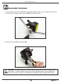
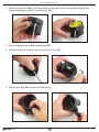
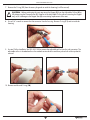
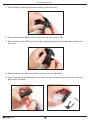
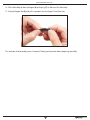
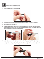
www.sherwoodscuba.com
INTRODUCTION
The instructions set forth in this document are intended to guide the experienced scuba equipment repair technician
through the standard service procedure for this Sherwood regulator.
It is assumed that the technician possesses basic scuba equipment repair training, proper tools and the skill
necessary to perform the service. If you have not received regulator service training provided by Sherwood Scuba
specifically for this equipment, do not attempt to perform the service described in this document.
Service parts for Sherwood equipment are sold only to Authorized Sherwood Dealers.
Before attempting to perform service read this manual in its entirety. There are warnings and cautions contained in
the manual that may affect your safety or the safety of the regulator user.
If you are uncertain as to whether you are qualified to perform this service contact your regional Sherwood Scuba
Distributor for technical assistance.
USE OF WARNINGS, CAUTIONS AND NOTES
!
WARNING:
Indicates a potentially hazardous condition or situation which, if not avoided, may
result in serious injury or death.
!
CAUTION:
Indicates a potentially hazardous condition or situation which, if not avoided, may
result in minor injury. It may also be used to alert against unsafe practices.
NOTE:
Indicates an important point or reminder.
WHEN TO SERVICE
This Sherwood regulator should be inspected for service at least annually. In most cases a simple inspection,
and if needed, minimal adjustment not requiring the replacement of parts will be sufficient for continued use.
Guidelines for the Annual Inspection are included in this manual.
Sherwood regulators are designed and tested to perform acceptably under typical recreational diving conditions up
to 300 hours of use.
If the regulator has been subjected to more than 300 hours of use or it has not received the benefit of careful
post-dive cleaning and storage in a clean environment, a standard service overhaul is required.
In any case the Sherwood regulator described in this manual should receive a standard service overhaul at
least every two years to maintain optimal performance. The standard service overhaul includes disassembly,
cleaning, inspection, replacement of seals, lubrication, reassembly and adjustments.
Sherwood Scuba offers a standard service kit that contains the parts recommended to be replaced in connection
with the standard service overhaul.
2
www.sherwoodscuba.com
ANNUAL INSPECTION GUIDELINES
1. Visually inspect the first and second stage for signs of damage or deterioration. Mouthpieces with tears or other
damage should be replaced.
2. Retract hose protectors and inspect the hose over its entire length for signs of damage including blisters, deep
cuts or separation at the crimped fittings. If these signs are present the hose must be replaced and standard
service overhaul is recommended.
3. Insert a soft probe through the exit port of the exhaust cover and lift the Exhaust Valve to inspect it for cuts, tears
or contaminated surfaces. Perform this examination from both sides of the Exhaust Cover to observe the entire
perimeter of the Exhaust Valve. If damage to the Exhaust Valve is found a complete overhaul is recommended.
If the Exhaust Valve or the sealing surfaces on the Housing are contaminated with debris, the Exhaust Cover
must be removed and the surfaces must be cleaned. Instructions for removing and replacing the Exhaust Cover
appear in the Second Stage Service Guide. As a final check of the Exhaust Valve apply a moderate suction
(approximately minus 5 inches of water, moderate inhalation effort) to the second stage mouthpiece with the air
supply closed and the second stage purged. If leakage is detected a complete overhaul is recommended.
4. Inspect the first stage filter for evidence of contamination. Discolored filters indicate previous contact with
contaminated air. If evidence of contamination is present it is recommended that a standard service overhaul be
performed. In addition you should advise the customer that the regulator has been exposed to contamination
and that previously used air cylinders used should be inspected.
5.
Install an intermediate pressure gauge into one of the available LP ports.
6. Pressurize the regulator to approximately 500 psi and inspect for leakage. Note intermediate pressure. It
should not be greater than 150 psi. If no leakage is detected increase inlet pressure to 3000 psi. Again check
intermediate pressure. It should not exceed 150 psi. If intermediate pressure is out of range 140 ± 10 psi or
leakage is present a standard service overhaul is recommended.
7. Test the purge function. If there is not a strong surge of air, a standard overhaul is recommended.
8. Gently submerge the entire regulator and look for bubbles that indicate leakage. If leakage is present a standard
service overhaul is recommended.
9. If a test bench is available perform an inhalation test. Inhalation effort should not be greater than 2.0 inches
of water at opening and less than 5.0 inches of water at 15 SCFM. If a test bench is not available perform a
subjective breathing test. When properly adjusted the regulator should provide smooth and easy inhalation. If
difficulty with inhalation is suspected a standard overhaul is recommended.
3
www.sherwoodscuba.com
GENERAL COMMENTS
NOTE - Read this section before attempting to perform service.
1. Read the entire set of procedures that follows before starting to service. Steps taken out of sequence or without
the knowledge of the proper procedure could damage the regulator or otherwise complicate the service process.
2. Refer to the Illustrated Parts List while performing service. Each part is identified with an item number the first
time it appears in the text. Parts that are to be replaced with new parts in conjunction with an overhaul have
encircled reference numbers.
3.
Do not attempt to reuse parts that are designated for replacement. Retain discarded parts to show to the
customer to illustrate that a full overhaul service has been completed.
4. Work in a clean properly equipped area. Cleanliness is essential for all regulator servicing and is critical for
regulators that will be exposed to enriched air mixtures (Nitrox). Do not attempt to service if all required tools
and a clean work area are not available.
5. Work on one regulator at a time taking care not to mix parts from other regulators. Use only genuine Sherwood
parts. Parts that appear similar may have different features that are not easy to detect and may cause poor
performance.
6. Be careful to protect the finish on all surfaces of the regulator during the service procedure. When holding parts
in a vise use soft or padded jaws to prevent defacing surfaces.
7. O-rings are classified by the service they perform and are identified as either static or dynamic. Dynamic
O-rings are those that are subjected to movement and the effects of friction which tend to shorten the useful life
of the O-ring. Static O-rings are used to create a seal between non-moving parts and are not subject to the
same wearing effects. Static O-rings have a longer useful life and are not replaced unless they show signs of
deterioration or brittleness. Careful inspection of these O-rings is required before they are returned to service.
Lubrication of O-rings:
a. General - O-rings in most instances should receive only enough lubricant to ensure they are supple. A light
coating of lubricant should present a surface that glistens but without a defined layer of lubricant visible.
b. Ample – When an ample application of lubricant is specified it generally applies to a dynamic O-ring
subject to considerable motion or environmental conditions where a more generous application of lubricant
might be beneficial. In this situation there should be a light film or layer of lubricant visible.
8. When removing O-rings use a wooden, plastic or a soft brass tool to lift the O-ring out of its groove. Do not use
steel or other hard tools that might scratch sealing surfaces.
9. When instructed to use tools such as a hex key or a wrench, follow the standard convention to rotate clockwise
to tighten and counterclockwise to loosen unless otherwise directed.
10. When instructed to tighten a part until snug, it means to apply torque just until the part stops moving freely and
the torque requirement to advance it further rises markedly. When specific torque specifications are given there
is a necessity to ensure that the part is tightened enough to retain position or to create a seal. Unless you are
skilled at accurately estimating torque, a torque wrench should be used. Excessive torque may damage parts and
require replacement.
4
www.sherwoodscuba.com
ENRICHED AIR NITROX SERVICE
The Sherwood regulator presented in this manual has been designed and manufactured to allow the use of Enriched
Air Nitrox (EAN) gas with an oxygen component not to exceed 40%.
In order to maintain this option the user must ensure that the regulator is protected from the introduction of
hydrocarbons. The introduction of hydrocarbons into the regulator may increase the risk of fire when used with EAN.
When servicing the regulator, the technician must be aware of this requirement and exercise caution not to
contaminate the regulator with hydrocarbons. This requires a clean workplace, free of oil, grease, debris and other
contaminants. Additionally in order to return the regulator to EAN service, the overhaul procedure must have a
cleaning provision to remove all hydrocarbons before the regulator is reassembled. Do not substitute parts or use
lubricants other than Christo-Lube 111. Silicone lubricants are not acceptable and increase the risk of a fire hazard.
!
WARNING – The introduction of hydrocarbons, lint, dirt and other contaminants into the areas of
the regulator subjected to high pressures (greater than 500 psi) and EAN mixtures containing more
than 40% oxygen may constitute a fire hazard and may subject the user to serious injury.
FACILITY REQUIREMENTS
The service facility is perhaps the most important asset of any professional dive store. It should be clean, well lighted,
and stocked with a complete inventory of parts and manufacturer’s specialty tools for the products your store sells. As
a minimum requirement, your service facility should be equipped with the following items:
•
Ultrasonic Cleaner - Select the right size model that can keep up with the volume of regulators that your
store services. A built in timer and heater will help control the cleaning time and temperature of the solution,
since most solutions work best when heated.
•
Bench Mounted Vise - A vise is sometimes needed to hold the regulator secure – especially when removing
the first stage yoke retainer. Special care must be taken, however, to avoid damage that can result from improper
use of this tool. Be sure to follow the instructions provided in this manual.
•
Magnification Lamp - Strong lighting and magnification are essential requirements for performing a
thorough parts inspection - especially when locating the cause of a small leak.
•
Quality Wrenches & Sockets - When working with chrome plated brass parts, it is especially critical to use
the correct size wrench and to ensure that it fits properly over the part. The use of an adjustable wrench is very
likely to cause damage to your customer’s regulator, and should be strictly avoided at all times.
•
Calibrated Inch-Pound Torque Wrench - it is important to follow the manufacturer’s torque values
whenever they are specified, in order to avoid overtightening or under tightening a part. This is especially
important for smaller parts and fittings, when overtightening can easily damage the part.
•
Calibrated Foot-Pound Torque Wrench - Torque wrenches that can be set for both inch-pound and
foot-pound measurements generally tend to be less accurate than wrenches that are designed to measure torque
within a specific range.
•
Manufacturer’s Specialty Tools -Specialty tools are critically important to performing each step of
disassembly and reassembly according to each manufacturer’s procedures. Sherwood specialty tools are
required to perform service are listed on the following page.
5
www.sherwoodscuba.com
SECTION
1
SHERWOOD OCTO
RECOMMENDED TOOLS AND SUPPLIERS
The specialty tools identified below may be purchased from your Sherwood Scuba Distributor. Common tools are
available from several sources.
Including:
Sears Roebuck
Home Depot
Harborfreight Tools
www.sears.com/craftsman
www.homedepot.com
www.harborfreight.com
Common Tools
Open End Wrenches - 9/16", 5/8",1/2", 3/4”
Hex Tool 5/32"
Small Flat Blade Screw Driver
Diagonal Pliers (wire cutters)
Torque Wrenches 25 ft-lb and 60 in-lb
Flashlight
Compressed Air Gun
O-ring picks, plastic or soft metal
Magnifier
Specialty Tools
Poppet/Orifice Installation Tool
Blunt Probe/Pick
Dual Drive Adjustment Tool
Height Gauge
20-900-100
10-20-400
20-500-200
20-900-250
6
www.sherwoodscuba.com
SECTION
2
DISASSEMBLY PROCEDURE
1. Use a 3/4” open end wrench to stabilize the inlet connector (9) and a 5/8” wrench to rotate the hose fitting nut
counterclockwise to separate the hose assembly (26) from the inlet connector.
2. Remove the tie wrap (17)and mouthpiece (25).
!
CAUTION – When performing the next step to remove the Purge Cover be careful to avoid placement
of the probe or screwdriver between the Housing and the Diaphragm Retainer. Incorrect placement of
the screwdriver may increase the risk of damage to the Diaphragm requiring replacement of the part.
7
www.sherwoodscuba.com
3. Remove the purge cover (22) by inserting a probe at the entry point on the housing and lift the edge of the
cover enough to grasp it and lift it from the housing (12).
4. Remove diaphragm retainer (24) and diaphragm (23).
5. With the assistance of a small screwdriver to remove the C-clip (18).
6. Push the access plug (14) to remove it from the housing
8
www.sherwoodscuba.com
7. Remove the O-ring (11) from the access plug and set aside for cleaning (it will be reused).
!
CAUTION – Before performing the next step retract the Poppet (2) from the Adjustable Orifice (4) by
fully depressing the Demand Lever (5). Rotation of the Adjustable Orifice without retracting the Poppet
may result in damage to the Poppet Seat (8) necessitating replacement of the seat.
8. Use a 3/4” wrench to remove the inlet connector from the housing. Remove O-ring (11) and set aside for
cleaning.
9. Use tool Orifice Installation Tool (20-900-100) to remove the adjustable orifice from the inlet connector. The
adjustable orifice is threaded and must be rotated counterclockwise and then pushed with a blunt probe for
removal.
10. Remove and discard O-ring (10).
9
www.sherwoodscuba.com
11. Slide valve body (1) back and lift upward to remove it from the housing.
12. Remove the exhaust tee (16) from the housing by removing the two screws (15).
13. Remove the exhaust valve (13) from the housing by grasping the valve and stretching the tab to release it from
the housing.
14. Rotate the adjuster screw (3) counterclockwise to remove it from the valve body.
15. Cover the open end of the Valve Body with your finger to restrain the Poppet and use a probe to push the Cam
(6) free of the Valve Body.
10
www.sherwoodscuba.com
16. Tilt the Valve Body to allow the Poppet (2) and Spring (7) to slide out of the Valve Body.
17. Grasp the Poppet Seat (8) and pull to separate it form the Poppet. Discard the Seat.
This concludes the disassembly process. Proceed to Cleaning and Inspection before beginning reassembly.
11
www.sherwoodscuba.com
SECTION
3
GENERAL CLEANING PROCEDURE
1. Thermoplastic, silicone rubber and anodized aluminum parts, such as diaphragms, accent trim, adjustment
knobs, static O-rings, and thermoplastic housings.
a. Soak in a solution of warm water and ordinary liquid dish detergent. Scrub with a soft nylon bristle brush
to remove deposits.
b. Rinse with fresh water and blow dry with clean low pressure compressed air.
2. Chrome-plated Brass and Stainless Steel parts a. Soak in a solution of warm water and ordinary liquid dish detergent. Scrub with a soft nylon bristle brush
to remove deposits.
b. Thoroughly rinse with fresh water.
c. If deposits cannot be removed with above process, soak parts in dilute solution of white vinegar
(50% water) for approximately 30 minutes and scrub with a nylon brush. Use of an ultrasonic cleaner
will accelerate this process. Do not subject thermoplastic or rubber parts to vinegar solution or ultrasonic
cleaning.
d. Rinse first with freshwater and follow up with a final rinse in deionized (distilled) water. Tap water
typically contains minerals that will leave undesirable residue on the cleaned parts if final rinse is omitted.
3. Hoses a. Corrosion or mineral deposits on the metallic fittings on hoses may be cleaned using the procedure
presented above provided that care is taken to just dip only the metal fittings at each the end of the hose
into the cleaning solution. Take care to prevent entrance of the solution into the hose interior.
b. Rinsing should include flushing the interior of the hose with fresh water followed by drying with
compressed air.
12
www.sherwoodscuba.com
SECTION
4
REASSEMBLY PROCEDURES
1. Install a new poppet seat (8) into the poppet (2).
2. Install the adjustment screw (3) into the valve body with an initial insertion of only one or two threads.
3. Place spring (7) inside valve body (1).
4. Use poppet Poppet Insertion Tool 20-900-100 to guide the poppet into the valve body. Note that notch in the
poppet must align with the cross hole in the valve body. After the poppet is aligned, insert the cam (6) with the
flat side facing toward the spring (7) to capture the poppet.
5. Hold the valve body so that the adjustment screw is at the left and the spring is visible though the air jet opening.
This should align the valve body so that the cam is below the center line of the valve body. Place the demand
lever (5) onto the cam by spreading the legs of the demand lever enough to slip it onto the cam. Operate the
demand lever to observe that it moves the poppet.
13
www.sherwoodscuba.com
6. Install the cleaned O-ring (11) onto the inlet connector. Note the O-ring groove is closest to the end with fine
threads.
7. Install a new lubricated O-ring (10) onto the Adjustable Orifice (4) and then insert the adjustable orifice into
the Inlet Connector (9). Note that insertion is at the end of the inlet connector with the coarse threads. Use the
Orifice Installation Tool 20-900-100 to thread the adjustable orifice rotating it clockwise until it comes to a stop.
Then rotate the Adjustable Orifice counterclockwise two full turns. This will establish the approximate correct
Demand Lever height after the Inlet Connector is installed.
8. Install the cleaned exhaust valve (13) into the housing. Be certain that the tab is captured in the hole in the
housing and that the exhaust valve fully closes.
9. Install the exhaust tee (16) and secure with the two screws (15).
10. Install the valve body into the housing aligning the square feature on the valve body with the indexing feature in
the housing.
14
www.sherwoodscuba.com
!
CAUTION – Before performing the next step retract the Poppet (2) from the Adjustable Orifice (4) by
fully depressing the Demand Lever (5). Rotation of the Adjustable Orifice without retracting the Poppet
may result in damage to the Poppet Seat (8) necessitating replacement of the seat.
11. Install the Inlet Connector (9) into the housing taking care to depress the demand lever fully to retract the poppet
to prevent contact with the adjustable orifice as the inlet fitting is rotated during insertion. Use a 3/4 “ wrench to
tighten. (Apply approximately 40 in-lbs torque).
12. Install a cleaned and lubricated O-ring (11) onto the access plug (14) and insert the access plug into the
housing. Secure with the C-clip (18).
13. Remove the port plug (19) from the access plug.
14. Insert a 5/32 “ hex tool to engage the adjuster screw and rotate clockwise to advance the adjuster screw until it
comes to a gentle stop. Reverse the rotation to retract the adjuster screw one and one half turns.
15. Temporarily attach the partially assembled second stage to a fully assembled and adjusted first stage with an
intermediate pressure set between 140 and 150 psi. Place the Dual Drive Adjusting Tool 20-500-200 between
the hose and the inlet connector.
15
www.sherwoodscuba.com
16. Pressurize the regulator so that intermediate pressure acts on the second stage. There may be air leaking by the
poppet until a final adjustment is made. Check the height of the Demand Lever position above the edge of the
Housing with the Height Gauge. It should be approximately 3/16”. If an adjustment is necessary, engage the
blade feature of the Dual Drive Adjusting Tool with the slot in the Adjustable Orifice. Depress the Demand Lever
to retract the Poppet and rotate the Adjustable Orifice clockwise to lower the Demand Lever and in the opposite
direction to raise it. Release the Demand Lever and check the height. Continue repeating the process until the
height is correct.
17. Install the diaphragm (23) and diaphragm retainer (24).
18. Install purge cover (22). If an air leak is detected when the purge cover is installed the demand lever may be set
too high. Repeat step 16 if necessary.
19. Depressurize the regulator assembly and remove the Dual Drive Adjusting tool. Install the hose assembly (26)
and tighten the swivel nut to approximately 40 in-lbs torque. Push the hose protector (20) toward the housing to
cover the hose fitting completely.
20. Use a 5/32” Hex Tool to install the LP Port Plug (19) into the Access Plug (14). Check the opening effort
(cracking pressure) of the second stage. It should be between 1.2 and 1.8 inches of water pressure. If it needs
to be adjusted, remove the LP Port plug, insert the 5/32” Hex Tool in the Adjustment Screw (3) and rotate it
clockwise to increase effort and counterclockwise to reduce opening effort.
21. Install the Mouthpiece (25) and secure with a tie wrap (17).
This concludes the reassembly procedure.
16
www.sherwoodscuba.com
SHERWOOD OCTO SECOND STAGE
ITEM
PART #
DESCRIPTION
ITEM
PART #
DESCRIPTION
1
SHV7014
Valve Body
15
SHV7027
Screw
2
SHV7020
Poppet
16
SHV7024
Exhaust Tee
3
SHV7019
Adjustment Screw
17
SHV7026
Tie Wrap
4
SHV7016
Adjustable Orifice
18
SHV7025
C Clip
5
SHV7015
Demand Lever
19
SHV7023
Port Plug, LP
6
SHV7018
Lever Cam
20
SHV7032
Hose Protector, Short
7
SHV7017
Spring
21
SHV7031
Hose Protector, Long
8
SHV7005
Poppet Seat
22
SHV7097
Octo Purge Cover
9
SHV7013
Inlet Connector
23
SHV7090
Diaphragm
10
SHV7071
O-ring
24
SHV7012
Diaphragm Retainer
11
SHV7070
O-ring
25
SHV7028
Mouthpiece
12
SHV7021
Housing
26
SHV7530
Hose Assembly w/ O-ring
13
SHV7006
Exhaust Valve
27
SHV7075
O-ring
14
SHV7022
Access Plug
17